Abstract
In the paper, a feedback hybrid control including a force feedback control and a position control is proposed to control a four degree of freedom (4-dof) upper limb exoskeleton for supporting human movement at the shoulder, elbow and wrist joints. The novelty of the paper is that it has been able to control all the interaction forces at all links in the exoskeleton robot by using the proposed control. The desired interaction forces at the links and desired position are compared with the measured interaction forces and position, respectively. Then the torque at the shoulder, the torque elbow and the torque wrist joints are controlled to compensate the force error and the position error. The gains of the proposed controller are optimized by using the Balancing Composite Motion Optimization (BCMO). The simulation and control of the 4-dof upper limb exoskeleton using the proposed control is carried out in the paper to show that the interaction forces and the position of the exoskeleton track their desired values.
Highlights
- The upper limb exoskeleton has four degrees of freedom
- The combination of force control and position control in a hybrid controller
- The hybrid controller is optimized using Balancing Composite Motion Optimization
- The upper limb exoskeleton can support human operator's movement
- It can control the interaction torques at shoulder, elbow and wrist joints
- It can control the motions of shoulder, elbow and wrist joints
1. Introduction
The upper limb exoskeleton is an external structure in the shape of human upper limb and is directly attached to human upper limb by using brackets. It is equipped with force sensors for sensing the vector of interaction forces exerted by the human operator and the upper limb exoskeleton, and actuators for exerting necessary torques in revolute joints at wrist, elbow and shoulder [1-3]. The review of control systems in the active exoskeleton was presented in [4]. In the feed forward control system, the human operator’s interaction forces are considered as disturbance. The interaction force between human operator and an upper limb exoskeleton can be estimated by using a disturbance observer or using the force sensors [5], [6]. The target of the controller is to control the human operator’s force as small as possible [7], [8]. In force feed forward control of the upper limb exoskeleton for supporting human movement model [9], [10], a force sensor was placed at the end effector to measure the interaction force exerted by the human operator. The measured interaction force of the human operator’s hand was transformed to the torques at joints using Jacobian transposed matrix. Then a Proportional Derivative (PD) feed forward controller will control the torque at joints of the upper limb exoskeleton to compensate the torques exerted by the human operator. The force feed forward control method is popular because of its robustness and reliability for exoskeleton; recently it has been generalized to force feedback control method to feedback desired interaction force to human lower limb [11]. The force feedback control is very useful to control the interaction force at the end effector using Jacobian transposed matrix. The controlling torques exerted by the exoskeleton at joints interact with the torques exerted by the human operator. These interation torques at joints make the misalignments between human operator’s joints and the exoskeleton’s joints. In order to reduce the misalignments we can use the hybrid force and position control at shoulder, elbow, and wrist joints [12]. In this paper, a feedback hybrid control that is including a force feedback control and a position control is proposed to control the upper limb exoskeleton to support human movement. The feedback hybrid force and position control aims to track the desired interaction force feedback to the human operator’s hand, and control position of the exoskeleton to track a desired position. A scenario is conducted with two stages. Stage 1: the human operator actively exerts force to guide the upper limb exoskeleton to the desired position. Without the supporting of the upper limb exoskeleton, the operator has to carry the external load and the exoskeleton. Stage 2: the positions of joints are measured by sensors placed at joints and the desired interaction force at the end effector is computed based on the current position of the exoskeleton. In stage 2, there are force sensors located at the links to measure the actual interaction forces. The errors between the desired interaction forces and the measured interaction forces at the links will be transformed to the torques at joints by using the transposed Jacobian matrices. The feedback hybrid controller will control the torques at joints to control the interaction forces at the links and the position of the exoskeleton. The current interaction forces at the links of the upper limb exoskeleton are controlled as close as possible to the desired interaction forces. Besides, the current position of the exoskeleton are controlled as close as possible to the desired position. The gains of the feedback hybrid controller are optimized by using the Balancing Composite Motion Optimization (BCMO) [13]. The numerical simulation shows that the interaction forces and the position of the exoskeleton track their desired values.
2. Model of a 4-DOF upper limb exoskeleton
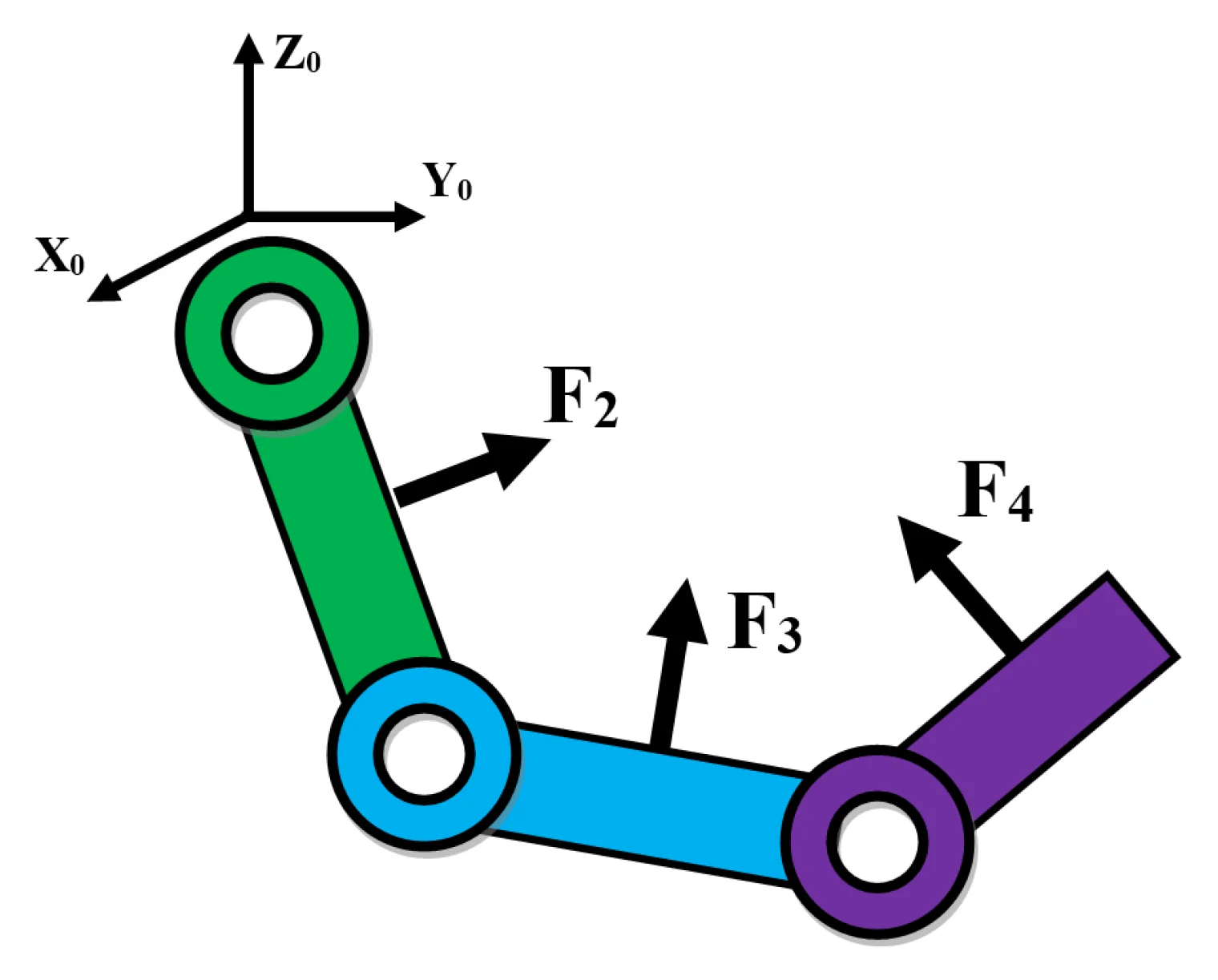
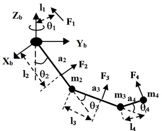
The model of a 4-DOF upper limb exoskeleton is shown in Fig. 1. It has four degree of freedom (4-DOF) including two joints at the shoulder (, ), one joint at the elbow (), and one joint at the wrist (), on 3 links: shoulder , elbow , and wrist . The lengths and masses of three links are represented by , , and , , respectively. The forces , , , , are the interaction forces at links 1, 2, 3, 4, respectively. The lever length between the line of the interaction force and the axis of joint is (1, 2, 3, 4). The control torques at joints 1, 2, 3, 4 are controlled by electrical motors located at joints 1, 2, 3, 4, respectively.
Fig. 1A 4-DOF upper limb exoskeleton
The Denavite-Hartenberge (D-H) parameters for 4-DOF Upper limb Exoskeleton is shown in Table 1.
Table 1Denavite-Hartenberge (D-H) parameters for 4-DOF upper limb exoskeleton
Link | ||||
1 | 0 | 0 | + | |
2 | 0 | 0 | – | |
3 | 0 | 0 | ||
4-1 | – | 0 | ||
4-2 | 0 | 0 | 0 | – |
In Table 1, the parameters ai are constant. Only the variables (1, 2, 3, 4) vary by rotation around axis. From D-H table, the homogeneous transformation matrices are obtained using Eq. (1), [14]:
The homogeneous transformation matrix that transforms the reference coordinate which is attached to the end effector to the base coordinate or the fixed base can be calculated by multiplying the individual transformation matrices as follows:
3. Feedback hybrid interaction force and position control design
The dynamics equation of motion of the upper limb exoskeleton under force control is derived in Eq. (3). It is constructed in matrix form, which is suitable for a Multi Degree of Freedom (MDOF) system [15]:
where, is vector of angles of rotation at joints 1, 2, 3, 4; is vector of angular velocities at joints 1, 2, 3, 4; is vector of angular accelerations at joints 1, 2, 3, 4; is vector of controlling torques exerted by direct current (DC) motors at joints 1, 2, 3, 4; is vector of torques exerted by human operator at the joints 1, 2, 3, 4; , , , are matrix of inertia masses, vector of Coriolis and centrifugal forces, vector of gravitational forces, respectively.
The detail elements of the matrix of inertia masses, vector of Coriolis and centrifugal forces, vector of gravitational forces are shown in the Appendix.
is the joint friction force vector which is model as the viscosity friction. The joint friction of joint (1, 2, 3, 4) is expressed as follows [16], [17]:
where, are coefficients of viscosity friction of joint (1, 2, 3, 4), respectively.
In this paper, a scenario containing two stages is considered:
Stage 1: At the beginning, a human operator actively moves the robot by exerting the vector of human operator’s torques to guide the exoskeleton robot to the desired position. The human operator has to carry the external load and the robot’s weight.
Stage 2: The position sensors installed at the joints measure the angles and speed of the joints. The desired interaction force at the end effector is computed proportionally to the angular rotation, the angular speed of the wrist’s joint, and the gravitational force of the mass of the wrist, whereas the current interaction force is measured by a force sensor installed in the end effector. The force controller compares the current interaction forces at the links with the desired interaction forces to generate the torques at joints 1, 2, 3, 4 of the exoskeleton to support the human movement. Besides, the position controller will control the current position of the exoskeleton as close as possible to the desired position.
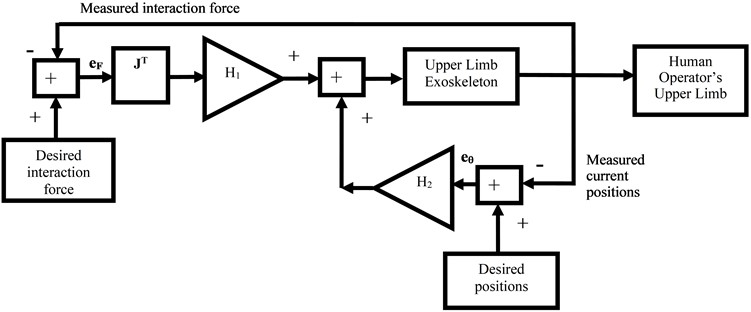
The block diagram of the interaction force control system is shown in Fig. 2. In stage 1, the human operator exerts torques to move the upper limb exoskeleton. In stage 2, the controller controls torque at the joints 1, 2, 3, 4 of the exoskeleton to control the interaction forces at the end effector and the links 1, 2, 3. The desired interaction force at the end effector is computed based on the positions and velocities of the wrist joint.
Fig. 2Block diagram of feedback hybrid interaction force and position control system
In Stage 1: the human operator actively applies force to move the exoskeleton in the desired motion using the operator’s arm. The human operator’s forces exerted at the links are modeled as a nonlinear spring and damper model:
where, is vector of human interaction torques at joints 1, 2, 3, 4; is the virtual springs’ stiffness of the interaction force model ( 1, 2, 3, 4); is the virtual dampers’ damping of the interaction force model ( 1, 2, 3, 4); ( 1, 2, 3, 4) is the lever length between the line of the human operator’s force and the axis of joint ; is vector of the desired positions of the exoskeleton at joints 1, 2, 3, 4; is vector of the current positions of the exoskeleton at joints 1, 2, 3, 4; is vector of the desired angular speeds of the exoskeleton at joints 1, 2, 3, 4; is vector of the current angular speeds of the exoskeleton at joints 1, 2, 3, 4; is the interaction force at link ( 1, 2, 3, 4); is the maximum interaction force can occur at link ( 1, 2, 3, 4); is the Jacobian matrix ( 1, 2, 3, 4), where is the vector of coordinates of the location of the interaction force ( 1, 2, 3, 4) in the global frame or the base . is the rotation matrix of local frame placed at link ( 1, 2, 3, 4) which transforms the vector of interaction force at the local frame attached to link to the global frame at the base (details of Jacobian matrices and rotation matrices are shown in the Appendix); (2,…, 4) is the length of link .
In Stage 2: the upper limb exoskeleton supplies the torque in order to follow and support the human operator’s movement. At this stage, the human operator will be supported with the exoskeleton. In Eq. (8), the desired interaction forces of the exoskeleton to the human operator are computed to support the human movement:
where, , , are virtual coefficients.
The errors between the desired interaction forces and the current interaction forces at the links are defined as follows:
where, is the desired interaction force at the link ( 1, 2, 3, 4); is the measured interaction force at the link (1, 2, 3, 4).
In reality, the current interaction force at the links 1, 2, 3, 4 can be measured by force sensors or load-cells. For simulation, the measured interaction force can be modeled as follows:
where, is the noise in the measurement; is the interaction force exerted by human operator; , are the coefficients of the disturbance in the measurements and human operator’s force, respectively.
The desired interaction force and the measured interaction force are considered as the input and feedback output of the controller, respectively. Then the error between them will be transformed to the torques at joints by using Jacobian matrices:
To compensate the human operator’s torques and support the human movement, the feedback hybrid control is proposed as follows [18], [19], [20]:
where, is the proportional gain of the force feedback controller; is the proportional gain of the position controller.
The control voltage at joints , , (1, 2, 3, 4), are controlled following the torques in Eq. (13). In order to keep the control voltage under the supply voltage, the saturation function is used as follows:
where, (1,…, 4) (V) is controlled voltage of DC motor ; (1, 2, 3, 4) is the saturation function; (V) – supply voltage of DC motor ; (1, 2, 3, 4) (Nm) is ratio of controlling torque and maximum allowed torque at motor ; (1, 2, 3, 4) (Nm) is maximum allowed torque or stalling torque of motor .
The torque generated by the Permanent Magnetic Direct Current (PM DC) motor is directly proportional to the armature current due to the interaction between the stator field and the armature current:
where, (A) is current through the armature winding of DC motor , (Nm/A) is torque constant of DC motor .
The relationship between the current and voltage of electrical motor is expressed in Eq. (15), [21], [22]:
where, (V) is voltage which controls PM DC motor , the rotor accelerates until a steady state operating condition is attained; (Ω) is resistance of armature winding of PM DC motor ; (V/(rad/s)) is electrical constant of PM DC motor , (rad/s) is current speed of PM DC motor ; (H) is inductance of armature winding of PM DC motor ; is the ratio of the gearbox of PM DC motor .
Substitute Eqs. (14) in (15), the relationship between the output torque generated by motor and control voltage (1,…, 4), when and negligible, is as follows:
4. Numerical simulation
In the simulation of the interaction force control using software program, the parameters of the system are shown in the Table 2.
The desired angles and angular speeds of the exoskeleton’s joints are:
The initial positions and initial speeds of the joints of the exoskeleton are:
In the simulation, the Eqs. (4) to (18) are simultaneously executed and solved with the Eq. (3) by using ode solver ode45 in software program.
The results of the simulation using the generalized force feedback control: the movement of joints in the joint space are shown in Fig. 3, 4. The simulated interaction forces are compared with the simulated desired interaction forces in Fig. 5.
Table 2Parameters for 4-DOF Upper limb Exoskeleton in the simulation program
Parameters of the system | Values |
Link length , , (m) | 0.30, 0.40, 0.20 |
Link mass , , (kg) | 0.50, 0.3, 0.5 |
Distance from joint to interaction force , ..., (m) | 0.20, 0.20, 0.20, 0.20 |
Virtual coefficients: (Ns/rad), (N/rad), (N) | 0.5, 0.5, 0.5 |
Frictional viscous parameters ,..., (Nms/rad) | 0.3, 0.3, 0.3, 0.3 |
Inertia moments (kg.m2) | diag[0.00, 0.30, 0.40, 0.20] |
Inertia moments (kg.m2) | diag[0.80, 0.50, 0.40, 0.60] |
Supply voltage parameters ,...,(V) | 12.0, 12.0, 12.0, 12.0 |
Stiffness , ..., parameters of the interaction force model (N/m) | 10e3, 10e3, 10e3, 10e3 |
Damping , ..., parameters of the interaction force model (Ns/m) | 10e1, 10e1, 10e1, 10e1 |
Maximum interaction forces (N) | 2, 3, 2, 1 |
Torque constant parameters ,...,(Nm/A) | 0.002, 0.003, 0.002, 0.001 |
Back electro motive force (Voltage) constant parameters ,...,(Vs/rad) | 0.001, 0.001, 0.001, 0.001 |
Resistor motor parameters ,..., (Ω) | 3, 3, 3, 3 |
Ratio gearbox parameters ,..., | 250, 250, 250, 250 |
Optimal proportional gains of the Hybrid Controller: , | 101, 343 |
Maximum allowed torques ,..., (Nm) | 2, 3, 2, 1 |
The disturbance from outside environment (N) | |
The coefficients of the disturbance in the measurements and human operator’s force | 1, –1 |
Simulation time (s) | 20 |
Fig. 3The desired positions and measured positions of joints (rad)
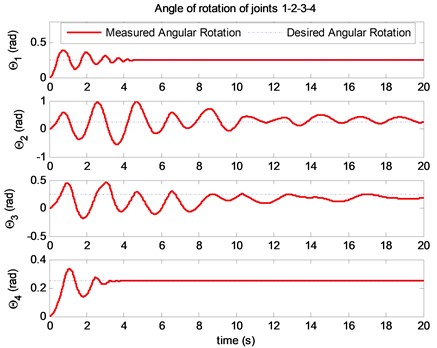
In Fig. 3, the movement of the exoskeleton is moved by the human operator intention and the exoskeleton will control the interaction force between human operator’s hand and the exoskeleton’s end effector to meet a desired interaction force. The actual angular rotations of , , , of the exoskeleton are converging to their desired values. The objective of the hybrid control is not only controlling the positions of the exoskeleton but also controlling the interaction force at the links.
Fig. 4The desired angular velocities and measured angular velocities of joints (rad/s)
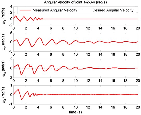
Fig. 5The desired interaction force and the measured interaction force at links (N)
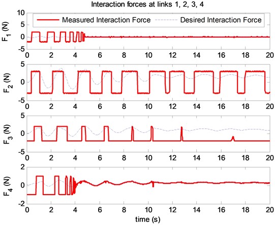
The desired interaction forces and the simulated interaction forces at the links are shown in Fig. 5. Root mean square of the error between the desired interaction force and the measured interaction force at the end effector is defined as follows:
The objective of the hybrid controller is to optimize the . In the paper, the optimal solution of the RMS is solved by using the Balancing Composite Motion Optimization (BCMO) [13]. In the BCMO, we set the initial values of BCMO as follows.
– The Maximum Generation: MaxGen = 10.
– The Population Size: NP = 50.
– The Lower Bound of the solution space: LB = 1.
– The Upper Bound of the solution space: UB = 500.
The optimal proportional gains of the hybrid controller 101 and 343. The = 0.46 (N).
5. Conclusions
The interaction forces between the human operator and the exoskeleton robot are an interesting problem for researchers. In this paper, a feedback hybrid control which combines the force feedback control and position feedback control has been proposed to control a 4-DOF upper limb exoskeleton. The human operator actively moves his arm at the beginning, then the exoskeleton is controlled to support the human operator in his desired motion. The errors between the desired interaction forces and the measured interaction forces at the links are transformed to the torques exerted at joints using Jacobian transposed matrices. The misalignment between the joints of exoskeleton and the corresponding joints of human are reduced using position control. The gains of the feedback hybrid controller are optimized by using the Balancing Composite Motion Optimization (BCMO). The numerical simulation shows that interaction forces and the position of the exoskeleton track their desired values.
References
-
Jose L. Pons, Wearable Robots: Biomechatronic Exoskeletons. Wiley, 2008, https://doi.org/10.1002/9780470987667
-
R. A. R. C. Gopura and K. Kiguchi, “Mechanical designs of active upper-limb exoskeleton robots: State-of-the-art and design difficulties,” in the IEEE International Conference on Rehabilitation Robotics (ICORR), Jun. 2009, https://doi.org/10.1109/icorr.2009.5209630
-
H. S. Lo and S. Q. Xie, “Exoskeleton robots for upper-limb rehabilitation: State of the art and future prospects,” Medical Engineering and Physics, Vol. 34, No. 3, pp. 261–268, Apr. 2012, https://doi.org/10.1016/j.medengphy.2011.10.004
-
K. Anam and A. A. Al-Jumaily, “Active exoskeleton control systems: state of the art,” Procedia Engineering, Vol. 41, pp. 988–994, 2012, https://doi.org/10.1016/j.proeng.2012.07.273
-
Michael Mistry, Peyman Mohajerian, and Stefan Chaal, “Arm movement experiments with joint space force fields using an exoskeleton robot,” in IEEE 9th National Conference on Rehabilitation Robotics, 2005, https://doi.org/10.1109/icorr.2005.1501130
-
C. Silawatchananai and M. Parnichkun, “Force control of an upper limb exoskeleton for virtual reality using impedance control,” in 2011 IEEE International Conference on Robotics and Biomimetics (ROBIO), pp. 2342–2347, Dec. 2011, https://doi.org/10.1109/robio.2011.6181648
-
Kazerooni Homayoon, “Human robot interaction via the transfer of power and information signals,” IEEE Transactions on Systems, Man, Cybernetics, Vol. 20, No. 2, pp. 450–463, 1990, https://doi.org/10.1109/robot.1989.100212
-
Hayashibara Y., Tanie K., Arai H., and Tokashiki H., “Development of power assist system with individual compensation ratios for gravity and dynamic load,” in IEEE/RSJ International Conference on Intelligent Robots and Systems, pp. 640–646, 1997, https://doi.org/10.1109/iros.1997.655079
-
J. Tang, J. Zheng, and Y. Wang, “Direct force control of upper-limb exoskeleton based on fuzzy adaptive algorithm,” Journal of Vibroengineering, Vol. 20, No. 1, pp. 636–650, Feb. 2018, https://doi.org/10.21595/jve.2017.18610
-
T. C. Nguyen, M. Parnichkun, M. T. T. Phan, A. D. Nguyen, C. N. Pham, and H. N. Nguyen, “Force control of upper limb exoskeleton to support user movement,” Journal of Mechanical Engineering, Automation and Control Systems, Vol. 1, No. 2, pp. 89–101, Dec. 2020, https://doi.org/10.21595/jmeacs.2020.21689
-
H. J. Lee, K.-S. Kim, and S. Kim, “Generalized control framework for exoskeleton robots by interaction force feedback control,” International Journal of Control, Automation and Systems, Vol. 19, No. 10, pp. 3419–3427, Oct. 2021, https://doi.org/10.1007/s12555-020-0097-2
-
M. Hessinger, M. Pingsmann, J. C. Perry, R. Werthschutzky, and M. Kupnik, “Hybrid position/force control of an upper-limb exoskeleton for assisted drilling,” in 2017 IEEE/RSJ International Conference on Intelligent Robots and Systems (IROS), pp. 1824–1829, Sep. 2017, https://doi.org/10.1109/iros.2017.8205997
-
T. Le-Duc, Q.-H. Nguyen, and H. Nguyen-Xuan, “Balancing composite motion optimization,” Information Sciences, Vol. 520, pp. 250–270, May 2020, https://doi.org/10.1016/j.ins.2020.02.013
-
M. W. Spong, S. Hutchinson, and M. Vidyasagar, Robot dynamics and control. Wiley, 2004.
-
Sanh D., Phong D. V., Phong P. D., Khoa D. D., and Thang N. C., “Problem of determining reaction forces of mechanical constraints,” in Proceedings of International Symposium on Robotics and Mechatroncis, pp. 129–135, 2009.
-
T. Tjahjowidodo, F. Al-Bender, and H. van Brussel, “Friction identification and compensation in a dc motor,” IFAC Proceedings Volumes, Vol. 38, No. 1, pp. 554–559, 2005, https://doi.org/10.3182/20050703-6-cz-1902.00093
-
Liu H. et al., “An experimental study on Cartesian impedance control for a joint torque-based manipulator,” Advanced Robotics, Vol. 22, No. 11, pp. 1155–1180, 2008.
-
R. P. Borase, D. K. Maghade, S. Y. Sondkar, and S. N. Pawar, “A review of PID control, tuning methods and applications,” International Journal of Dynamics and Control, Vol. 9, No. 2, pp. 818–827, Jun. 2021, https://doi.org/10.1007/s40435-020-00665-4
-
Guangye Liang, Wenjun Ye, and Qing Xie, “PID control for the robotic exoskeleton: application to lower extremity rehabilitation,” in IEEE International Conference on Mechatronics and Automation, 2012.
-
S. Oh, E. Baek, S.-K. Song, S. Mohammed, D. Jeon, and K. Kong, “A generalized control framework of assistive controllers and its application to lower limb exoskeletons,” Robotics and Autonomous Systems, Vol. 73, pp. 68–77, Nov. 2015, https://doi.org/10.1016/j.robot.2014.10.001
-
Sabri Centinkunt, Mechatronics. John Wiley & Sons, 2007.
-
D. G. Alciatore and M. B. Histand, Introduction to Mechatronics and Measurement Systems. New York: McGraw Hill, 2007.
About this article

The research funding from Vietnam Academy of Science and Technology (VAST) under grant number CSCL03.03/23-24.
The datasets generated during and/or analyzed during the current study are available from the corresponding author on reasonable request.
Thang Cao Nguyen: literature, methodology. Anh Dong Nguyen: editing. Manukid Parnichkun: control and measurement. My Thi Tra Phan: simulation and design.
The authors declare that they have no conflict of interest.
