Abstract
The dynamics analysis and control of the upper limb exoskeleton for supporting user movement is done by using the force feedforward control model. Based on a novel combination of Proportional Derivative (PD) force feedforward and Proportional Integral (PI) feedback control model [1], this paper proposes a method to assist the user’s movement for a three degree of freedom exoskeleton structure. When the user exerts force at the handle, the force is measured by a force sensor placed at the handle. These sensed forces are applied to command the actuators to support the human movement and reduce the disturbance effects of the device. This technique is well established approach in haptics for reducing the effects of inertia, damping, friction, centrifugal and Coriolis forces and gravity of haptic device [2]. Simulation result shows the torque controlled by robot to assist human for a desired loading motion.
Highlights
- Kinematic analysis of the computer controlled electro-mechanical system.
- Dynamic analysis of the computer controlled electro-mechanical system.
- Proportional Derivative Feedforward controller is designed for the computer controlled electro-mechanical system.
- Proportional Integral Feedback controller is designed for the computer controlled electro-mechanical system.
- The computer controlled electro-mechanical system is verified by Matlab software.
- The device can be applied for rehabilitation, virtual reality, education, entertainment.
1. Introduction
An upper limb exoskeleton (Fig. 1) is an electromechanical system of mechanical structure, sensors, actuators and a digital processing unit (dSPACE or DAQ card) which is controlled by a Personal Computer [3, 4] (Fig. 2 and Fig. 4). Upper limb exoskeleton equipped with a force sensor which can sense the force exerted by the user, and can produce necessary torques through joints at wrist, elbow and shoulder for supporting human movement, has been developed [1, 2, 5]. When the user needs to move, the user exerts force at a handle where the exerting force is measured by a force sensor. Then, a force feed forward control will generate force for movement assistant to perform some tasks: moving freely and lifting some objects vertically and horizontally. In short, it can move according to the wearer's instructions. Besides, there exists an upper limb exoskeleton which has a force feedback system for perceiving tangible sensation and guiding human movement. The device is designed to measure angle of rotation of the joints on the arm of the wearer and can generate control forces for interacting with other objects in remote environment [3, 6]. It has force feedback system that is capable of transmitting feedback force to help the user perceiving remote environment. Virtual Reality technology includes real-time simulation and creating realistic sensations related to multiple senses. The senses include see, hear, touch, smell, taste. Between these five senses, force feedback can be applied to the sense of touch for a realistic feel. In 2011, Chaiyaporn S. and Manukid P., designed an impedance control model using system state observer to estismate the joint torque applied by human to 6DOF upper limb exoskeleton [6]. The device is used for perceiving contact force interacting between human and virtual environment. Recently, detailed reviews of force feedback arm exoskeleton were given by Lo H. and Xie S. [7], and in Proietti T. et al. [8]. Perry C. et al. [9] introduced four applications that an arm exoskeleton could be used for human. There are up to four main applications with their special control algorithms: a) Rehabilitation – human interaction with robot in two ways active and passive, b) Haptic device, human interacting with the virtual environment, while arm exoskeleton responding to human a force to perceive reality, c) Master device, master-slave control, interaction force appeared in the master being sent by the robot-slave, d) Assisted human device – when worn on the wearer making the wearer feel lighter load with the support of the arm exoskeleton. Thus, there is much interesting in generating and perceiving tangible sensations in many applications.
Fig. 1Model of arm exoskeleton structure with force feedback system, left – model of arm exoskeleton structure with force feedback (4 degrees of freedom) including 2 joints in the shoulder, 2 joints in the elbow (J1-J4), 5 links (0-4), and a handle held by the hand (EE) [14, 15], right – human body from BodyWorks [9]
![Model of arm exoskeleton structure with force feedback system, left – model of arm exoskeleton structure with force feedback (4 degrees of freedom) including 2 joints in the shoulder, 2 joints in the elbow (J1-J4), 5 links (0-4), and a handle held by the hand (EE) [14, 15], right – human body from BodyWorks [9]](https://static-01.extrica.com/articles/21689/21689-img1.jpg)
In the applications for rehabilitation, L-EXO (Light Exoskeleton – Frisoli [10], Vertechy [11]), is a force-feedback arm designed for human arm rehabilitation that can generate control force in the right hand, the end point held by the wearer. The control force responds from the end of the arm exoskeleton in the direction along the moving trajectory or in the direction perpendicular to the trajectory. Due to the design towards weight reduction, L-EXO developed by Frisoli [10], used a electrical motor system connected to cables and reduction gears to increase the control torque at the joints. The force command was directly converted into the electrical motor torque command using transposed Jacobian method. The limitation of L-EXO (2007) is the quality of controlling the feedback force due to the use of cables. In their further research [11], a new design for L-EXO design was developed to be able to operate in two modes: passive movement and active movement and was applied in reaching movement exercises for patients. Depending on the supporting level, the passive movement mode high supports the user in executing their required movement. The active movement mode only guides and less supports the user in executing the required movement.
In the applications for master – slave control, force feedback control has many advantages. For example, when working with micro objects, the dexterity, precision, and speed are significantly improved when the force acting on the object can be felt and controlled in real time. The development of such miniature manipulations with a great interest in surgery and micro robotics and was reported by Carrozza M. C., et. al. [12]. Manipulating micro objects with a traditional micro gripper without the usual built-in force sensor requires a camera to get visual feedback. This approach results in a simple 2D image and a lack of sense of contact between the manipulator and the object in contact, making it difficult to locate the tool [12]. A micro gripper with built-in load cell can solve this, therefore, is suitable for holding objects firmly, while avoiding any excessive pressure on the object. The application of force feedback control helps to recreate, according to human activity, the forces sensing ability for robot during the controlled process in a remote or virtual environment [13].
In the applications for haptic, the application of force feedback control helps to recreate, according to human activity, the forces sensing ability for robot during the controlled process in a remote or virtual environment [13]. The application of electrical motors in the joints increases the quality of the feedback force, but the engines are also required to generate more torque to offset the engine's weight. Due to the increased torque, the engines are also required to increase both in volume to ensure sufficient power and the quality of the feedback force to degradation. Recently, Chaiyaporn S., Manukid P. [3], designed and built a novel control model using a Particle Swarm Optimization (PSO) control algorithm for upper limb exoskeleton. Sensors used to measure the rotation angle of joints are incremental encoder (1024 pulses/ cycle). The 6 DOF device has load cells to measure the force exerted by the user, actuators (for shoulder elbow, and wrist), specialized DAQ card connected to a PC which works as a controller and displays force feedback to user. Fig. 2 shows its subsystems. To enhance the control quality of the arm exoskeleton, the upper limb exoskeleton system has control system using PSO algorithm.
Fig. 2Architecture of AIT upper limb exoskeleton [3]
![Architecture of AIT upper limb exoskeleton [3]](https://static-01.extrica.com/articles/21689/21689-img2.jpg)
In the assist application, PID controller for upper limb exoskeleton has been used commonly, for example, in research of Elizabeth A. et al. [4] on simulation and preliminary experiment of dynamic and control of cable driven upper limb exoskeleton. The dSPACE DS1103 was shown in the experiment set up of the robot to control the motions of six electrical motors with built-in encoders in the arm exoskeleton based on the closed loop speed control. The PID control method has been applied in the field of force feed forward control. Thang N. C. et. al. [16], has proposed the force feed forward control to compute the torque of upper limb exoskeleton to support the force exerted by the user. The authors suggested that the PI feedforward controller could assist the current force of the user if the user force decreased to zero. In the paper, PI controller could be changed to novel PD feedforward controller. The authors suggested that the controller could predict the future by considering the Derivative term. In literatures, there are also some researches using PD in the field of force feedforward control. Jing Tang et al. [1], proposed the fuzzy adaptive PD controller for direct force control of 2-DOF upper limb exoskeleton consisting of a heavy load model. Fuzzy control is suitable for specific system with more appropriate gains when compared with the conventional PD control which uses fine tuned gains. Fuzzy control can adjust the control parameters automatically and optimally towards a more adaptive and optimum control. Another feed forward model to compensate the arm’s weight in the ARMin V robot was presented in the research of Fabian Just et al. [5]. Based on the idea of compensating the torque exerted by the mass locating at the center of gravity, force feedforward control was applied to reduce the physical effort of the holding arm’s weight to 26 %. It was shown in Hulin T. [2], that the feedforward controller clearly decreased the effort of astronaut wearing spacesuit to 10 % of the total effort along predefined trajectories.
The importance as well as practical significance of force feedback/feedforward control for the robot increases with the development of robotics. This research is motivated by two current projects in Institute of Mechanics (VAST) and Asian Institute of Technology (AIT) where we focus on an arm exoskeleton with force assistant using force feedforward control. These devices contain both hardware and software and are designed and built for rehabilitation purpose. Besides, control algorithm design is a very important part of this research. As the result, the available controls such as Proportional Derivative (PD) control [1], as well as the work of and Fabian Just, et al. [5], Dimitar Chakarov et al. [14, 15], are used as initial references for implementation of force control of the device.
This paper presents the development of a 3 DOF upper limb exoskeleton with force sensing ability. The device can track the position and magnitude of the contact force between the user’s hand and the robot. Furthermore, it can produce necessary forces through joints at wrist, elbow and shoulder in order to support the force exerted by the user. One strategy is considered in which there are two steps. Step 1 starts when the user exerts force at handle where the contact force is measured by a force sensor. The position and the orientation of the force are tracked by using encoders located at joints. In Step 2, a force feed forward control is used to control motors located at joints to support the current force generated by the user to perform some tasks: moving freely and lifting some objects vertically and horizontally. Simulation results show the performance of force control for a desired loading motion.
2. Modeling of 3DOF Upper limb exoskeleton
In this section, a model of a 3DOF upper limb exoskeleton is explained as shown in Fig. 3. The arm exoskeleton system is a robotic chain including a joint at the shoulder (J1), a joint at the elbow (J2), and a joint at the wrist (J3), with 3 links: upper link (connecting shoulder and elbow), lower link (connecting elbow and wrist), and the last link for hand holding called handle (or end effector). Three geared DC motors are installed at these joints with encoder sensors used to measure rotation angle. A force sensor used to measure force exerted by the user’s hand is placed at handle in the end effector. Its D-H table is shown in Table 1. The physical parameters of upper limb exoskeleton are listed in Table 2.
Fig. 33-DOF upper limb exoskeleton model
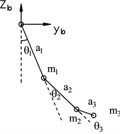
Table 1Denavite – Hartenberge (D-H) table
Joint | ||||
0 | 0 | |||
1 | 0 | 0 | ||
2 | 0 | 0 | ||
3 | 0 | |||
0 | 0 | 0 |
Table 2Physical parameters of upper limb exoskeleton (COM: center of mass)
Link | Length, , (m) | Mass, , (kg) | COM, (m) | Moment of inertia, (kg.m2) |
1 | 0.270 | 2.15 | [0, 0, 0] | [0, 0.1, 0.1] |
2 | 0.287 | 2.31 | [0, 0, 0] | [0, 0.1, 0.1] |
3 | 0.080 | 2.15 | [0, 0, 0] | [0, 0.1, 0.1] |
In Table 1, the parameters ai are constant. Only the variables (1, 2, 3) vary by rotation around axis. From D-H table, the homogeneous transformation matrices are obtained using Eq. (1), Spong M. W., Hutchinson S, and Vidyasagar M. (2004) [17]:
The homogeneous transformation matrix that transforms the reference coordinate {3}, which is at the end – effector to the reference coordinate {}, can be calculated by multiplying individual transformation matrices as follows:
The dynamics equation of motion is presented as the following equation:
Above equation is derived using Lagrange equation [3]. The Lagrange equation can be conveniently constructed in matrix form which is suitable for MDOF system [18]. Where, (Nm) – vector of control torques in electrical motor in joint 1, 2, 3, respectively. (N) – vector of forces exerted by user () after being projected to the reference coordinate {}, which is the inertial frame or base, by multiplying with orientation matrix following Eq. (4):
(N) – vector of forces exerted by user and measured by force sensor placed in the reference coordinate {3} attached to the handle. The force exerted by user is known as human-machine interaction force and measured by a three axis force sensor; – the homogeneous transformation matrix; – the end effector’s orientation matrix which is defined by the first three rows and the first three columns of the transformation matrix, given in Eq. (5):
– the end effector location vector is defined by the first three rows and the last column of the transformation matrix, given in Eq. (6):
– the Jacobian matrix, the symbol () denotes the transpose of a matrix. (Sabri Centikun, [19]):
– matrix of inertia, – matrix of inertia masses, – vector of Coriolis and centrifugal forces, – vector of gravity forces:
where matrix of rotary inertia moment of links at center of mass:
matrix of rotary inertia moment of electrical motors:
and:
– joint friction force vector.
Friction modeling: The joint friction is modeled as the combination of both Coulomb and viscosity friction according to Tjahjowidodo et al. (2005), [20], and Liu et al. (2008), [21], which can be expressed as:
At constant speed, the applied torque is equal to the friction torque, which is determined by curve fitting. The identified joint frictions are summarized in Table 3.
Table 3Friction coefficients
Joint | Coulomb (Nm) | Viscosity (Nms/rad) |
1 | 3.3385 | 0.0123 |
2 | 1.6291 | 0.0023 |
3 | 0.1767 | 0.0004 |
3. Controller design
3.1. Controller design for PD force feedforward strategy
In this paper, we consider a strategy:
Step 1: At the beginning, a user moves the robot by rotating its joints following a desired loading motion. The force of the user () is generated to compensate the weight of exoskeleton and the force of damping and loading. The joints angles and the forces exerted by the user can be measured by the angular sensors (encoders) and the force sensors which are installed in the robot.
Step 2: At the same time, the robot becomes active, it scales the force exerted by the user by a Proportional Derivative (PD) feed forward controller to support the human force. To scale the current user’s force, it uses proportional gain ; and predicts the future user’s force, it also uses Derivative gains: .
Therefore, the upper limb exoskeleton (the robot) is used to generate the torques in order to assist the human. The PD force feedforward controller is utilized to compute the command torques for the electrical motors. These command torque will be feeded to the Proportional Integral (PI) controller which is arranged after the PD controller. The PI controller will use feedback current sensed by hall sensors to control the torque of electrical motors.
In order to deal with this strategy, a PD feedforward control approach with Eq. (12) is applied:
where:
where , – vector of joints angles and forces of the user which are sensed by encoders and force sensors, at time .
Specification constant gains matrix:
Because there are limitations in the effort of electrical motors and safety purpose for the user, the torques of joints are limited by limiting the gains . Gain is the level of support, [2].
In Step 1, the user applies some force to move the exoskeleton by moving in a desired loading motion using his own hand. In Step 2, by using a mechanical device as the exoskeleton, the burden in his joints is computed by Eq. (13) and then scaled for controlling the electrical motors to generate assistant force in the robot to assist human by Eq. (12).
3.2. Controller design for PI feedback control strategy
In the control block diagram of the upper limb exoskeleton which is shown in figure 4, the electrical motors (actuators) is controlled by voltage . The torque generated by a Permanent Magnetic Dirrect Current (PM DC) motor is directly proportional to the armature current due to the interaction between the stator field and the armature current:
where (A) is current through the armature winding of DC motor , (Nm/A) is torque constant of DC motor .
The relationship between the current and voltage of electrical motor is shown in Eq. (16), [19]:
where (V) are voltage is applied to a PM DC motor, the rotor accelerates until a steady state operating condition is attained; (Ω) is resistance of armature winding of DC motor ; (V/(rad/s)) is electrical constant of DC motor , (rad/s) is speed of DC motor , (H) is inductance of armature winding of DC motor .
Substitute Eqs. (15) in (16), the relationship between the output torque generated by motor and voltage , when and can be neglected, is shown as follows:
Fig. 4Control blocks diagram of upper limb exoskeleton
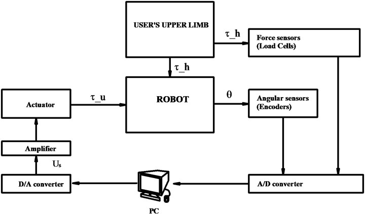
As shown in the Fig. 4, the electrical motor is controlled by a feedback control law in which the amature current will be sensed by a hall sensor. Besides, the controller needs the presences of the digital processing unit or DAQ card connected with the Personal Computer (PC). The hall sensor will feedback the amature current which represents the torque exerted by the electrical motors following Eq. (15). The Proportional Integral controller will compare the difference between the desired inputs torque provided by the force feedforward controller, the torque following Eq. (12) with the output torques generated by electrical motors following Eq. (17) which is fedback by hall sensors. As the consequence, the control law to control voltages of electrical motors of the Proportional Integral controller is shown in Eq. (18):
where, , are proportional and integral gains of the PI controller for electrical motors , respectively, , are, desired input torques commanded by controller to control the electrical motor and output torques generated by electrical motors , respectively.
4. Simulation results
In this example, the constant gains of PD and PI controllers are selected as follows:
The force exerted by the user is set as follows:
The initial condition of the upper limb exoskeleton is set as follows:
The Matrix of rotary inertia moment of links and electrical motors are set as follows:
The Torque constants, Electrical constants, Resistances, Inductances of DC motors are set as follows [1]:
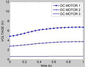
According to the feed forward control as explained in section 3, the following control torques are computed for supporting the force exerted by hand of the user. Substituting the Eqs. (4-14) and Eqs. (17, 18) in Eq. (3) using the parameters in Eq. (19) to Eq. (23), then Eq. (3) is sloved by ode45 in Matlab software. The rotation of the joints 1, 2, 3 are shown in Fig. 5. The control torques of electrical motors at joint 1, 2, 3 are shown in Fig. 6, 7, and 8, respectively. Fig. 9 shows the speed curves of the exoskeleton’s electrical motors versus of time. Fig. 10 shows the voltage curves of the exoskeleton’s electrical motors versus of time. The simulation time is 1 second.
Based on the simulation results, the dynamics analysis and control of the upper limb exoskeleton for movement assistant is done by using the force feedforward control model. The novel PD force feed forward combined with PI feedback control model in [1] is applied to assist the user’s movement by supporting the human shoulder, elbow, and wrist along the desired loading motion. These sensed forces are scaled and commanded to the actuators to support the human movement and to reduce the disturbance effects of the device. This technique is a well established approach in haptics for reducing the effects of inertia, damping and friction, centrifugal and Coriolis forces and gravity of device [2].
Fig. 5Rotation of joints
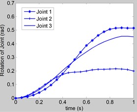
Fig. 6Control torque u1
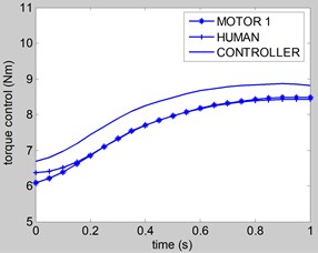
Fig. 7Control torque u2
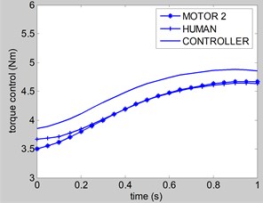
Fig. 8Control torque u3
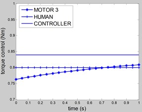
Fig. 9Speed of joints
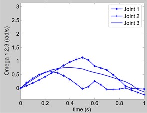
Fig. 10Voltage of DC motors
5. Conclusions
In the paper, the kinematic and dynamic analysis of a upper limb exoskeleton using PD force feed forward control combined with PI feedback control model is researched. The upper limb exoskeleton uses a 3 axis force sensor to measure the human-machine interaction force. The torques are generated at joints at wrist, elbow and shoulder by electrical motors. When a user exerts force at the handle, the force is measured by the force sensor and then scaled by controller to drive the electrical motors at joints to support the user movement. The PD force feedforward control strategy is developed to compute the command torques of the controller. The PI feedback control strategy for three electrical motors is developed in the model. The solutions of joints motion and joints torque control are obtained by solving the motion equation using the Matlab software. In order to evaluate the performance of the model, a simulation is conducted by a Matlab program using ODE45. The results show that the upper limb exoskeleton can support the movement of the user for the desired loading movement.
References
-
Jing Tang, Jianbin Zheng, Yang Wang Direct force control of upper-limb exoskeleton based on fuzzy adaptive algorithm, Journal of Vibroengineering, Vol. 20, Issue 1, 2018, p. 636-650.
-
Hulin T., Alessandro C., Vodermayer B., Riener R. Evaluation of force feedforward control for actuators with limited dynamics and time delay. STAMAS Workshop – Smart Technology for Artificial Muscle Applications in Space, Madrid, Spain, 2015.
-
Chaiyaporn Silawatchananai, Manukid Parnichkun Haptic control of an arm exoskeleton for virtual reality using PSO based fixed structure H∞ control. International Journal of Advance Robotic Systems, 2019, https://doi.org/10.1177/1729881419849198.
-
Elizabeth A. Brackbill, Ying Mao, Sunil K. Agrawal, Madhu Annapragada, Venkatesh N. Dubey Dynamics and control of a 4-dof wearable cable-driven upper arm exoskeleton. IEEE International Conference on Robotics and Automation, Kobe, Japan, 2009, p. 2300-2305.
-
Fabian Just, Ozhan Ozen, Stefano Tortora, Robert Riener, Georg Rauter Feedforward model based arm weight compensation with the rehabilitation robot ARMin. International Conference on Rehabilitation Robotics (ICORR), 2017, p. 72-77.
-
Chaiyaporn Silawatchananai, Manukid Parnichkun Force control of an upper limb exoskeleton for virtual reality using impedance control. IEEE International Conference on Robotics and Biomimetics, 2011, p. 2342-2347.
-
Lo H. and Xie S. Exoskeleton robots for upper-limb rehabilitation: State of the art and future prospects. Medical Engineering and Physics, Vol. 34, 2012, p. 261-268.
-
Proietti T., et. al. Upper-limb robotic exoskeletons for neurorehabilitation: a review on control strategies. IEEE Reviews in Biomedical Engineering, Vol. 9, 2016, p. 4-14.
-
Perry C., et. al. Upper arm power exoskeleton design. IEEE/ASME Transactions on Mechatronics, Vol. 12, Issue 4, 2007, p. 408-417.
-
Frisoli A., Borelli L., Montagner A., Marcheschi S., Procopio C., Salsedo F., Bergamasco M., Carboncini M., M. Tolaini, B. Rossi Arm rehabilitation with a robotic exoskeleleton in virtual reality. International Conference on Rehabilitation Robotics, 2007, p. 631-642.
-
Vertechy R., Frisoli A., Dettori A., Solazzi M., Bergamasco M. Development of a new exoskeleton for upper limb rehabilitation. International Conference on Rehabilitation Robotics, 2009, p. 188-193.
-
Carrozza M. C., Dario P., Jay L. P. S. Micromechatronics in surgery. Transactions of the Institute of Measurement and Control, Vol. 25, Issue 4, 2003, p. 309-327.
-
O’Malley M. K. Mechanical design of distal arm exoskeleton for rehabilitation. International Conference on Rehabilitation Robotics, Vol. 2011, 2011, p. 5975428.
-
Dimitar Charakov, Ivanka Veneva, Mihail Tsveov, Dimitar Trifonov Design and control of a force reflecting Arm exoskeleton for virtual reality applications. Proceedings of the 14th International Conference on Informatics in Control, Automation and Robotics, Vol. 2, 2017, p. 335-342.
-
Dimitar Charakov, Ivanka Veneva, Mihail Tsveov A new upper limb exoskeleton for human interaction with virtual environment and rehabilitation tasks. 10th International Conference Mechatronic Systems and Materials, Opole, Poland, 2014.
-
Thang N. C., Manukid P., Tra My P. T., Gam L.T. H., Chung P. N., Hieu N. N. Force control of an upper limb exoskeleton for perceiving reality using force feed forward model. The 5th International Conference on Engineering Mechanics and Automation (ICEMA-5), Hanoi, Vietnam, 2019, p. 337-344.
-
Spong MW, Hutchinson S, Vidyasagar M. Robot Dynamics and Control. Wiley, 2004.
-
Sanh D., Phong D. V., Phong P. D., Khoa D. D., Thang N.C. Problem of determining reaction forces of mechanical constraints. Proceedings of International Symposium on Robotics and Mechatronics, Hanoi, Vietnam, 2009, p. 129-135.
-
Sabri Centinkunt Mechatronics. John Wiley and Sons, 2007.
-
Tjahjowidodo T., Al-Bender F., Brussel H. Friction identification and compensation in a dc motor. IFAC Proceedings Volumes (IFAC-PapersOnline), Vol. 38, Issue 1, 2005, p. 554-559.
-
Liu H., Liu Y. C., Jin M., et al. An experimental study on Cartesian impedance control for a joint torque-based manipulator. Advanced Robotics, Vol. 22, Issue 11, 2008, p. 1155-1180.
Cited by
About this article

This research is supported by Vietnam Academy of Science and Technology (VAST), project VAST01.09/20-21.
