Abstract
Parallel with significant growth in industry, especially mysteries related to energy engineering, condition monitoring of rotating systems have been experiencing a noticeable increase. One of the prevalent faults in these systems is fatigue crack, so finding reliable procedures in identification of cracks in rotating shafts has become a pressing problem among engineers during recent decades. While a vast majority of cracked rotors can operate for a specific period of time, to prevent catastrophic failures, crack detection and measuring its characteristics (i.e. size and its location) seem to be essential. In the present essay, a hybrid procedure, consisting of Deep Learning and Discrete Wavelet transform (DWT), is applied in detection of a breathing transverse crack and its depth in a rotor-bearing-disk system. DWT with Daubechies 32(db32) as wavelet mother function is applied in signal noise reduction until level 6, also its Relative Wavelet Energy (RWE) and Wavelet entropy (WE) are extracted. A characteristic vector that is a combination of RWE and WE is considered as input to a multi-layer Artificial Neural Network (ANN). In this supervised learning classifier, a multi-layer Perceptron neural network is used; in addition, Rectified Linear Unit (ReLU) function is exerted as activation function in both hidden and output layers. By comparing the results, it can be seen that the applied procedure has strong capacity in identification of crack and its size in the rotor system.

Highlights
- Classification of cracked rotors based on the crack’s depth can prevent unwanted stops in the rotor-bearing system.
- Due to the fact that creating cracks that will be near to real cracked shafts is a hard-working project, setting test rigs that result in time-domain vibration signals similar to theoretical.
- Discrete wavelet transform is able to distinguish invisible characteristics in time-domain signals, so it seems to be a powerful instrument in creating reliable features in classification.
- Results of the confusion matrix are approved of the ability of the proposed method.
1. Introduction
Because of a rapid growth in industry and technology, a vast majority of machines work in high-velocity, so potential faults in these devices can bring about many detriments. Rotating systems are one of the most widely used devices in modern and classic industries, for this reason analyzing these machines has become a favorite task among engineers.
A common rotor system is combined of disk, bearing and a shaft that the latter accounts as the heart of this complex. Numerous faults can occur in this system, but bearing and shaft’s faults are more rampant. Faults such as misalignment, cracks and rotor to stator rub can occur concertedly in rotor bearing systems. One of the prevalent faults in the rotor system is crack, especially fatigue crack that results from bending loads [1]. Since the 70’s, many scholars have been working on crack identification methods in rotating systems. During the two last decades not only crack identification procedures witnessed noticeable developments, but also, they have concentrated focus on vibration analyzing [2].
2. Previous works
Throughout recent years, scholars have been using numerous methods to find out crack symptoms in rotating systems; however, the inverse problem of the identification of cracks has not been commonly included [3]. To have a classification of used methods, we can classify them in two main categories: local and global methods. In the local procedures, normally non-destructive methods such as X-ray, Ultrasonic, Liquid penetrant and Eddy current can be used. On the other hand, for studying the features of structural systems with cracks, vibration-based crack detection methods are more powerful and superior than the other non-destructive crack identification methods. Because of their capacities in accurate and online crack detection [4].
Among the all vibration-based methods, signal processing techniques are more useful in online crack detection. Generally, different procedures such as finite element method, manners that consider breathing behavior of crack, time-frequency domain transforms such as HHT, continuous and discrete wavelet transforms, artificial intelligence such as Artificial Neural Network and things like these areas employed in modeling of faulted dynamic systems and processing of these systems vibration. In addition, some characteristics can be influenced by crack, for example in some articles, some harmonic and subharmonic components are introduced as crack’s present in rotating systems [5].
Sekhar compared numerous time-frequency methods and several faults features in a rotating shaft. In the mentioned article, by means of time-frequency domain manners, vibrations of the rotating system during its start-up were processed. To have a comparison between various types of faults in the rotor system such as rotor-to-stator rub, misalignment and crack, Sekhar employed a finite element method, then the equation motion of the system was solved by help of numerical procedures. Moreover, the effectiveness of three different time-frequency transforms, i.e., Hilbert-Huang, wavelet and short-time Fourier in crack identification were compared together. As a result, Sekhar claimed that HHT was less time-consuming. However, for noisy data CWT was more preferred over HHT [1]. A perfect literature of applying wavelet transforms in crack detection exists in Gómez’s paper [6].
In reality, crack in dynamic systems like rotor-system can breathe, i.e. close and open cyclical, because of their weights. One of the intensive impacts of a crack’s breath is it can change the system's flexibility (or stiffness), so in analyzing a cracked rotor this effect should be considered.
Until now, various methods have been applying to model breathing behavior: 1) Breathing mechanism model without weight considering. 2) Breathing mechanism model with weight considering. 3) Switching model (assuming crack is fully open or not is fully close). 4) Response-dependent breathing crack model. In cases, there are not any momentary stimulation, and system operate in stable circumstances (i.e. steady-state velocity), crack’s breathing behavior can be modeled by sinusoidal stiffness variation or by stepwise stiffness fluctuation that refer to 1-3 above methods have used a response-dependent breathing model to take into account the gradual opening and closing of the crack using the stress intensity factor at the crack front at each instant and then have found the amount of crack opening and hence the stiffness [7].
Mobarak and Wu have studied the dependence of the breathing mechanism on the crack location. In this work, a rotor system containing two discs, suffering a flat crack and has three-degree freedom are considered using the finite element method. Actually, the numerical method in Abaqus software was applied to the FEM model. In this research, dependency of crack breathing treatment to crack position and properties of unbalance force were approved. Two crack breathing areas were distinguished along the total length of the rotor where the unbalanced and balanced shaft stiffness may be same or different, linked to the unbalanced orientation of the force, amount, and location of the crack. As well as, four specific crack locations were identified along the shaft, where the crack remained completely closed or open or only acts as a balanced shaft [8].
Artificial intelligence (AI)-based techniques have great potential for identifying crack location and crack depth accurately in a rotating shaft. These methods consist of several steps: signal generation, signal processing, pattern classification and crack diagnosis. First, non-stationary and non-linear vibration signals that are generated from a cracked rotor should be inputted. Next, we ought to apply a multiresolution analysis (MRA) and discrete wavelet transform (DWT) techniques to process the vibration signals and to extract characteristic patterns. Finally, we should apply the AI based techniques (ANN, GAs, Fuzzy Inference, Hybrid techniques etc.) for pattern classification and selection. After these procedures, crack’s depth and its location can be identified. Gupta et al. applied an ANN to demonstrate faults such as cracks and imbalances in a rotor- bearing system. Then, by the help confusion matrix, the class of crack and unbalance was decided [9]. An extensive literature review on the use of artificial intelligence for fault diagnosis of rotating machinery has been presented by Ruonan and his colleagues [10].
Zhao et al., introduced a procedure that has capacity in identification of crack and misalignment in a rotor system which combines variational mode decomposition (VMD) and probabilistic principal component analysis (PPCA) to reduction environmental noises the captured vibration signals from an experimental rig and then gain signal feature extraction and fault classification by using CNN [11].
In [12] two approaches were used for crack detection in rotating machinery, model-based and signal-based approaches, were compared. Strength and weak points were discussed and compared for the two approaches using two representative applicable methods, in order to achieve a comparative overview of these two available techniques. Söffker et al. employed Proportional-Integral-Observer approach (i.e. is a novel model-based procedure) in demonstrating model-based capacities and restrictions. As a result, they presented a modern signal-technique which is a combination of support vector machine and wavelet transform. An intensive review on almost all applied procedures in the field of crack detection carried out by Sabnavis [13].
Relative wavelet energy as a feature vector was applied for the first time in 2009 by Ling Gue to classification EEG signals. In this work, a feature vector consisting of relative wavelet energy components was applied in distinguishing normal EEG signal and epileptic EEG signal [14]. Wavelet entropy is a measure of the degree of order/disorder of the signal and it indicates the latent dynamical properties of the non-linear signals [15]. Moreover, in 2012, Kumar used wavelet entropy and relative wavelet energy as inputs to Artificial Neural Networks to classify normal and faulted EEG signals.
In present work, a hybrid procedure is applied in classification of cracked and intact shafts in the experimented rotating system. This hybrid method is based on supervised deep learning algorithms. At first, noise is removed from the signal by means of discrete wavelet transform (DWT). In the following, the signal is decomposed until level 6 with ‘db8’ as wavelet mother function. Relative wavelet energy (RWE) and wavelet entropy (WE) are employed in construction of feature vectors. The feature vector (i.e. has four members) is used as an input to ANN. At the next step, a multi-layer Perceptron algorithm is employed as supervised learning of binary classifiers. In addition, Rectified Linear Unit (ReLU) is applied in both hidden and output layers to avoid overfitting.
3. Materials and methods
3.1. Discrete wavelet transform (DWT)
The continuous wavelet transform (CWT) of a signal, , is the integral of the signal multiplied by scaled and shifted versions of a wavelet mother function and can be defined by [16]:
Here and are called the scaling and shifting parameters, consequently. Calculation of wavelet coefficients at every possible scale is very time-consuming. Instead, if the scales and shifts are selected based on powers of two, the so-called dyadic scales and positions, then the wavelet analysis will be much more efficient. This type of analysis can be achieved of discrete wavelet transform:
Here and are alternatives for and consequently. The DWT of an indication is decomposed simultaneously employing a high-pass filter (HP) and a low-pass filter (LP) with impulse response. Output gives the detail coefficients (D) from the HP and also the approximation coefficients (A) from the low-pass one [17]. According to Nyquist principle, the resulted signal has half frequency bandwidth of the first signal and can be sampled. At each step of this decomposition process, the frequency resolution is doubled through filtering and the time resolution is halved through down sampling.
3.2. Relative wavelet energy (RWE)
Since the family set is an orthonormal basis for , the concept of energy is linked with the usual notions derived from the Fourier theory [18]. First, the number wavelet and the number of decomposition levels are selected. The energy at different decomposition levels (from to ) is the energy of wavelet coefficients and, in order to simply description, the energy of scaling coefficients is defined as the energy at decomposition level . Thus, the energy at each decomposition level is defined as [19]:
Then, the full energy of the signal after employing wavelet decomposition is achieved as:
Therefore, the relative wavelet energy (RWE) is defined as:
Clearly, and therefore the distribution are often considered as a time-scale density. Relative wavelet energy can show some crucial information concerning relative energy and associated frequency bands and might detect the degree of similarity between segments of a symbol. For this study we determine relative energies for each band before and after thresholding.
3.3. Wavelet entropy (WE)
The Shannon entropy gives a useful criterion for analyzing and comparing probability distribution, it provides a measure of the data of any distribution. The full WE can be defined as [15]:
The WE appears as an amount of the degree of order/disorder of the signal, so it can prepare beneficial information about the underlying dynamical process related to the signal. In fact, a really ordered process may be thought of as a periodic mono-frequency signal (signal with a tiny band spectrum).
3.4. Deep learning
Deep learning may be a subset of machine learning which is itself a subset of AI and statistics. Briefly, Deep Learning could be a Machine Learning procedure that employs the deep neural network; the deep neural network is that the multi-layer neural network that contains two or more hidden layers [20]. Fig. 1 illustrates the concept of Deep Learning and its relationship to Machine Learning.
Fig. 1The notion of machine learning
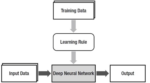
The deep neural network lies within the place of the ultimate product of Machine Learning, and therefore the learning rule becomes the algorithm that generates the model (the deep neural network) from the training data. The initial neural networks had an issue where the deeper (more) hidden layers were harder to coach and degraded the performance. The poor performance of the deep neural network is because of the failure of proper training. In this process three various showstoppers can be assumed: the vanishing gradient, computational load and last but not least overfitting. The vanishing gradient problem is greatly improved by employing the Rectified Linear Unit (ReLU) activation function and also the cross entropy-driven learning rule. Using improved gradient descent method can promote some benefits. The ReLU function is defined as:
To overcome the issue of overfitting in deep machine learning, dropout or regularization should be applied, but a huge amount of time is needed in terms of calculation. This is relieved to a large extent by the GPU and various algorithms [21]. Fig. 2 presents a schematic of multi-layer neural network, also the relationship between neurons (i.e. Deep learning).
Fig. 2Schematic of a multi-layer ANN (deep learning)
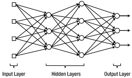
There are various programming algorithms for supervised machine learning that can be employed in binary classifiers; a binary classifier is a function which can decide whether or not an input, represented by a vector of numbers, belongs to some specific classes [22]. Here, specific classes mean healthy and cracked shafts with various depths. Perception is one the most well-known algorithms in this area, so in current work this algorithm is used.
3.5. Feature vector
To have a vision concerning a feature, a feature is defined as properties of a sample in forms of symbolic, numerical and even string arrays. If multiple elements about an object are put together, a feature vector can be made. Moreover, locating some feature vectors for different objects together can create a feature space. Feature vectors are employed broadly in machine learning due to its effectiveness and especially of representing objects in a numerical way to help with a vast type of analyses. Euclidean distance can be introduced as one of the simplest manners to compare the feature vectors of two different objects. Feature vectors are used in classification problems, artificial neural networks, and -nearest neighbor’s algorithms in machine learning [23]. In present work, because we decomposed signal until level 6, our feature vector consists of four features that are defined as:
3.6. Test rig
In current work, a CTC Piezoelectric accelerometer is applied in which vertical vibration signals are measured; moreover, to collect vibration signals, Baumuller B MaXX 3000 analyzer is used. To analyze intact and faulted signals, at first, collected signals are transported to PC by means of VIBROEXPERT CM400 software, then, MATLAB® programming language is employed for coding and analyzing. For binary classifying, Pattern Recognition Toolbox in MATLAB® is engaged.
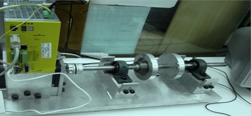
In Fig. 3, the test rig is shown. This experimental rig consists of a DC motor, a shaft, two journal bearings, two disks (are used in adding unbalancing force to the system) and as mentioned a Piezoelectric accelerometer, analyzer, and Personal computer.
Fig. 3Rig used for test setup
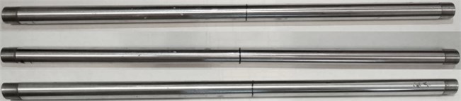
To create a crack close to real functional circumstances there are several procedures from Coping saw to propagated crack resulting from a notch with 3-point bending fixture; however, in this work to simulate breathing behavior of crack, wire cut is employed. Due to wire cut’s limitation, i.e. there are drawbacks to using a wire with too small a diameter [24], in three shafts grooves with thickness 0.3 millimeter and depths (i.e. three classes related to cracked shaft) near to 20 %, 30 % and 40 % of shaft diameter are made; in addition, for further information concerning EDM wire cut procedure [25] is a reliable reference. Fig. 4 displays three cracked shafts.
Class 1= Healthy shaft.
Class 2= Cracked shaft with relative depth equal to 20%d.
Class 3= Cracked shaft with relative depth equal to 30%d.
Class 4= Cracked shaft with relative depth equal to 40%d.
Fig. 4Cracked shafts in various depths
Mechanical characteristics of shaft and disks of experimented rotor-bearing-disk system are given in Table 1 and Table 2 respectively.
Table 1Properties of shaft
Properties | Amounts |
Diameter | 2 cm |
Total Length | 45 cm |
Length between two bearings | 20 cm |
Density | 7.85 g/cm3 |
Young's module | 200 GPa |
Table 2Properties of disks
Properties | Amounts |
Diameter | 10 cm |
Degree between each hole | 10° |
Mass | 2.0 kg |
Thickness | 1.5 cm |
4. Results
Transient Signals of the rotating system are captured during its start-up (i.e. first seven seconds); moreover, initial acceleration is 30. 60 rad/s2 and sampling frequency is equal to 2 kHz (time interval= 0.005 second). Analyzed signals by means of CM 400 software are transported to PC. In Fig. 5, intact and cracked shaft signals are presented in various depths in the time domain. Also, this set of graphs show noise reduced signals that are obtained from DWT noise reduction procedure to level 6 with db32. Vibration signals after noise reduction are compatible with theoretical signals that were introduced in [26].
From the graphs it can be seen that near to the second 1 the amplitude of vibration signal has a rapid growth due to crack, and this jump increases by increasing crack depth. This change is denoted in the last graph by a red circle. In current work, concept of relative wavelet energy and wavelet entropy are used in forming feature vector to classifying shafts. Fig. 6 demonstrates wavelet coefficients (i.e. detail and approximation) of cracked, in class 4, and intact rotors, belonging to class 1, until level 6 by means of db32 as wavelet mother function.
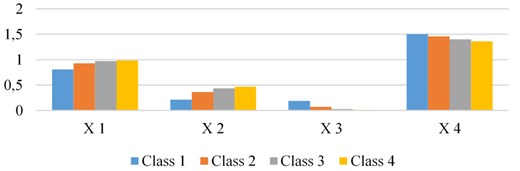
As stated in previous section, in current investigation, a feature vector combined of RWT and WE is applied. In Table 3, the average amount of feature coefficients of shafts belonging to various classes are demonstrated.
Fig. 5Noisy and noise reduced time-domain signals of healthy and cracked shafts in left and right sides respectively
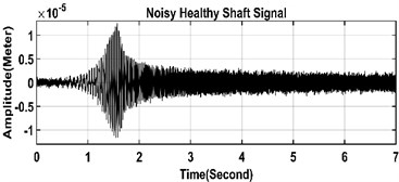
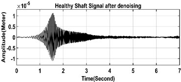
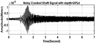
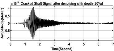
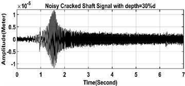
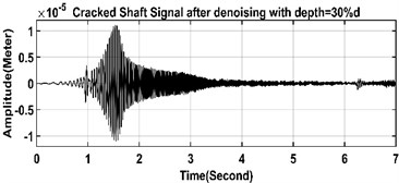
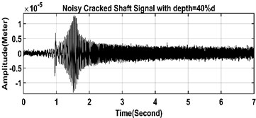
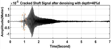
Fig. 6Details and approximation coefficients of DWT of healthy and cracked shafts
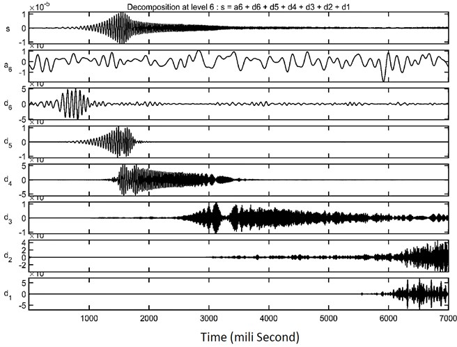
a) Healthy shaft
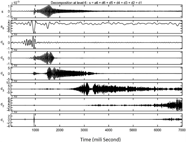
b) Cracked shaft (a = 40%d)
Table 3Average amount of feature coefficients
Class | X1 | X2 | X3 | X4 |
Class 1 | 0.809185 | 0.211998 | 0.190815 | 1.503474 |
Class 2 | 0.927499 | 0.366842 | 0.072501 | 1.461062 |
Class 3 | 0.971354 | 0.439087 | 0.028646 | 1.402919 |
Class 4 | 0.986062 | 0.469263 | 0.013938 | 1.360196 |
Consequently, Fig. 7 Shows the amount of X1 and X2 increased gradually; however, X3 and X4 experienced slight decline parallel with increasing in crack depth. It is obvious that feature coefficients are selected properly, because these coefficients can form a difference between the various kinds of classes.
Fig. 7Comparison of feature coefficients for different classes
To create a feature space, system is operated in two different initial acceleration (i.e. 30 and 60 rad/s2), also 50 different locations for unbalancing masses are located in two disks, so by changing initial acceleration and eccentricity 100 samples are generated for each classes. In Fig. 8 the features x3 and x4 are compared for class 1 and class 4 as example. This graph is drawn for some samples. However, in some points, features have overlap for two classes, in almost all spots these two classes have different amounts that can be used for effective classifying.
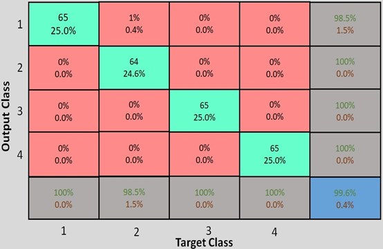
Among 100 various data for the four classes, 28 samples are employed for training, 7 and 65 samples are applied for validation and testing respectively. For training, validation and testing data the mean squared error is 1.4003e-22, 1.05886e-22 and 0.0037 consequently. ANN algorithm could classify different classes with an accuracy equal to 99.62 %. In Fig. 9 confusion matrix for training data that is resulted from ANN (here is deep learning) operation is shown. It can be seen that ANN among all samples just has one mistake that is related to class 2 (i.e. cracked shaft with relative depth equal to 20 % of shaft diameter).
Fig. 8Vibration signal patterns based on features x3 and x4. ‘O’ (blue) and’ *’ (red) indicate class 1 and class 4 respectively
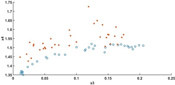
Fig. 9Confusion matrix of deep learning operation
5. Conclusions
In this research, a hybrid procedure consisting of discrete wavelet transform and deep learning procedures are employed in classifying cracked shafts in a rotating system with various crack depths. At the initial step of signal processing, collected signals are noise reduced by the help of discrete wavelet method to level 6. In the following, relative wavelet energy and wavelet entropy of vibration signals are calculated. Feature vectors are extracted based on RWE and WE. Then, these features are used in classifying different classes of shaft (i.e. healthy and cracked rotors in three depths). To classify, a multi-hidden layer Perceptron algorithm with Rectified Linear Unit (ReLU) function is exerted as activation function is introduced. By using ReLU, the Perceptron algorithm avoided overfitting, so the results that are shown in Fig. 8 state that this hybrid method has accuracy above 99.5 percent. This threshold of accuracy approves the fact that the introduced manner in classifying cracked rotors in consideration with crack size has reasonable success.
References
-
Harish Chandra N., Sekhar A. S. Fault detection in rotor bearing systems using time frequency techniques. Mechanical Systems and Signal Processing, Vol. 72, Issue 73, 2016, p. 105-133.
-
Xiang Jiawei, Chen Xuefeng Identification of crack in a rotor system based on wavelet finite element method. Finite Elements in Analysis and Design, Vol. 43, Issue 14, 2007, p. 1068-1081.
-
Bachshmid N., Penacci P. Crack effects in rotor dynamics. Mechanical Systems and Signal Processing, Vol. 22, Issue 4, 2007, p. 761-762.
-
Bachschmid N., Ezio Tanzi, Paolo Pennacchi Cracked Rotors: A survey on Static and Dynamic Behaviour Including Modelling and Diagnosis. 1st ed., Springer-Verlag, Berlin Heidelberg, 2010.
-
Kushwaha N., Patel V. N. Modelling and analysis of a cracked rotor: a review of the literature and its implications. Archive of Applied Mechanics, Vol. 90, 2020, p. 1215-1245.
-
Gómez María J., et al. Review of recent advances in the application of the wavelet transform to diagnose cracked rotors. Algorithms, Vol. 9, Issue 1, 2016, p. 19.
-
Darpe A. A. K., Gupta K., Chawla A. Coupled bending, longitudinal and torsional vibrations of a cracked rotor. Journal of Sound and Vibration, Vol. 269, Issues 1-2, 2004, p. 33-60.
-
Hossain Mobarak, Wu Helen Crack breathing behavior of unbalanced rotor system: A Quasi-static numerical analysis. Journal of Vibroengineering, Vol. 20, Issue 3, 2018, p. 1459-1469.
-
Gupta R. B., Singh S. K. Detection of Crack and Unbalancing in a Rotor System Using Artificial Neural Network, Advances in Engineering Design. Lecture Notes in Mechanical Engineering, Springer, Singapore, 2019.
-
Ruonan Liu, et al. Artificial intelligence for fault diagnosis of rotating machinery: a review. Mechanical Systems and Signal Processing, Vol. 108, 2018, p. 33-47.
-
Wang Zhao, et al. A Novel Method for identifying crack and shaft misalignment faults in rotor systems under noisy environments based on CNN. Sensors, Vol. 19, Issue 23, 2019, p. 5158.
-
Söffker D., Wei C., Wolff et al. S. Detection of rotor cracks: comparison of an old model-based approach with a new signal-based approach. Nonlinear Dynamics, Vol. 83, 2016, p. 1153-1170.
-
Giridhar Sabnavis, et al. Cracked shaft detection and diagnostics: a literature review. The Shock and Vibration Digest, Vol. 36, Issue 4, 2004, p. 287-296.
-
Ling Guo, et al. Classification of EEG signals using relative wavelet energy and artificial neural networks. Genetic and Evolutionary Computation Conference, Shanghai, China, 2009,
-
Rosso O. A., et al. Wavelet entropy: a new tool for analysis of short duration brain electrical signals. Journal Neuroscience Methods, Vol. 105, Issue 1, 2001, p. 65-75.
-
Sundararajan D. Discrete Wavelet Transform: A Signal Processing Approach. 1st ed., Wiley, Singapore, 2015.
-
Akansua Ali N., et al. Emerging applications of wavelets: a review. Physical Communication, Vol. 3, Issue 1, 2010, p. 1-18.
-
Rosso O., et al. EEG analysis using wavelet-based information tools, Journal of Neuroscience Methods, Vol. 153, Issue 2, 2006, p. 163-182.
-
Salwani M. D., Jasmy Y. Relative wavelet energy as a tool to select suitable wavelet for artifact removal in EEG. 1st International Conference on Computers, Communications, and Signal Processing with Special Track on Biomedical Engineering, Kuala Lumpur, Malaysia, 2005, p. 282-287.
-
Paluszek Michael, Stephanie Thomas Practical MATLAB Deep Learning: a Project-Based Approach. 1st ed., Apress, Berkeley, 2020.
-
Kim Phil MATLAB Deep Learning with Machine Learning, Neural Networks and Artificial Intelligence. 1st ed., Apress, Berkeley, 2017.
-
Freund Y., Schapire R. E. Large margin classification using the perceptron algorithm. Machine Learning, Vol. 37, Issue 3, 1999, p. 277-296.
-
Gutierrez Osuna R. Introduction to Pattern Analysis. Lecture Notes, Texas A&M University, 2005.
-
Wendorf Devin, Milos Mike Things to consider when wire and small-hole EDMing. XACT Wire EDM Corporation, 2009, https://www.xactedm.com/news/things-to-consider-when-wire-and-small-hole-edming/.
-
Masanori Kunieda, et al. Advancing EDM through fundamental insight into the process. CIRP Annals - Manufacturing Technology, Vol. 54, Issue 2, 2005, p. 64-87.
-
Rezazadeh Nima Investigation on the time-frequency effects of a crack in a rotating system. International journal of engineering research and technology (IJERT), Vol. 9, Issue 6, 2020, p. IJERTV9IS061017.
Cited by
About this article

