Abstract
In order to study the influence of heavy truck dynamic parameters on the vehicle’s ride comfort under the random road excitation, the weighted RMS (root-mean-square) acceleration responses of the vertical driver’s seat and cab pitch angle are chosen as objective function, a dynamic model of the vehicle with 10 degrees of freedom is established to simulate and analyze the results. The influence of different parameters of all the suspension systems of the vehicle, such as the stiffness and damping of the suspensions of the seat, cab, vehicle, and wheel, on the vertical driver’s seat and cab pitch angle are respectively analyzed. The study results show that the influence of the stiffness and damping parameters in the suspension systems on the vehicle ride comfort is very obvious. The vehicle’s ride comfort changes worse with the increase of the suspension stiffness and the reduction of the suspension damping, and vice versa. The study proposes an optimal range of the stiffness and damping parameters for the optimal design and control of the vehicle suspension systems, concurrently, the study can also provide a theoretical basis for the suspension system designed for heavy trucks.
Highlights
- The influence of heavy truck dynamic parameters on the vehicle’s ride comfort under the random road excitation is analyzed.
- A dynamic model of the vehicle with 10 degrees of freedom is established to simulate and analyze the results.
- The vehicle’s ride comfort changes worse with the increase of the suspension stiffness and the reduction of the suspension damping, and vice versa.
- The study proposes an optimal range of the stiffness and damping parameters for the optimal design and control of the vehicle suspension systems.
1. Introduction
Nowadays, the heavy truck market has increasingly higher performance requirements for vehicles. One of the most important factors of the vehicle is the vehicle’s ride comfort. The parameters of the vehicle dynamics system have an important influence on the vehicle’s ride comfort. The parameters of the heavy truck changed can strongly affect the vehicle’s ride comfort and road damage [1, 2]. In order to improve the driver’s ride comfort and road friendliness, the parameters of the vehicle dynamics system must be continuously improved. The previous researchers often use the half-vehicle, the full vehicle dynamic models, or the multi-body dynamic models to research the vibration of the vehicle. The analysis and evaluation of the influence of parameters of the different suspension systems, tires, speeds, and road surface levels on the driver’s ride comfort were studied [3-5]. The influence of the vehicle suspension system on road friendliness was also researched and optimized [1, 6-8]. In addition, the ride comfort of the heavy truck’s cab and the driver’s seat directly affects the driver’s work efficiency and physical health as well as driving safety. Especially, when heavy trucks traveling on random road surfaces, the excitation vibration could impact the vehicles cause the driver to feel uncomfortable, fatigued, and even cause occupational diseases such as spinal deformities and stomach problems. Therefore, improving the ride comfort of the driver and reducing the driver’s fatigue strength can not only ensure the health of the driver but also have important significance for ensuring the safety of the driver.
In recent years, improving the design of the cab and seat suspension systems has become a hot topic in the automotive industry. The simulation vibration of the vehicle was established in [9, 10], but only the influence of the parameters of the cab suspension system on the ride comfort was considered. The literature in Refs. [9, 11, 12] were to optimize and control the parameters of the driver’s seat and the cab suspension based on the vertical weighted RMS acceleration of the seat. The literature in Refs. [9, 12] used DOE technology to simulate and improve the parameters of the cab’s suspension system. The literature in Ref. [13] used a multi-body dynamics model of the cab suspension system. The excitation vibrations of the simulation model are measured through road tests, and the weighted RMS acceleration is used as the objective function. However, these studies only consider the effect of the cab suspension parameters on the vertical vibration. Therefore, it not fully reflects the influence of the vibration on the driver’s ride comfort on the different roads. When the vehicle traveling on the road, the road roughness surface, unbalanced inertia force of the engine, wind force, etc. will affect the vibration in three directions of the cab. The research results showed that the cab shaking also has a great impact on the driver’s ride comfort and physical health.
To solve this problem, a dynamics model of heavy trucks with 10 degrees of freedom was established in this paper. The random vibration of the road surface was used as the exciting function. The weighted RMS acceleration of the vertical driver’s seat and the cab’s pitch angle is used as the objective function to evaluate the vehicle’s ride comfort. Matlab/Simulink software was used to simulate the results. The effect of the sensitivity parameters of the suspension systems of the driver’s seat, cab, vehicle, and wheel on the ride comfort are analyzed and evaluated in Part 1 of this paper. The research results can provide a based design for the vehicle dynamics system.
2. The heavy truck dynamic model
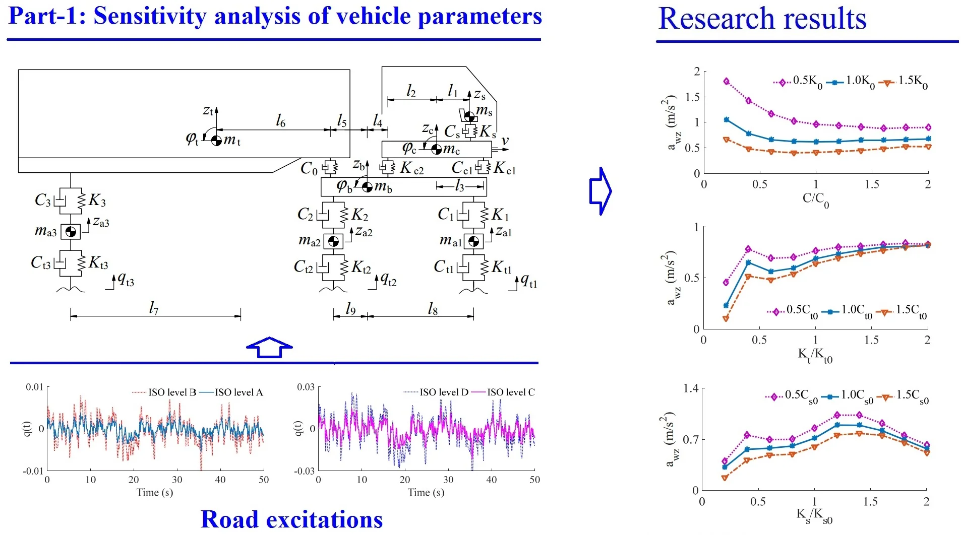
Based on the above research results in Section 1, it can be seen that there are currently three methods for modeling and solving the vehicle dynamics system: (1) The physical structure is used to simplify the vehicle system model; (2) using CAD software to model, then use CAE and other dynamic software to solve and optimize; (3) to combine two methods. This article uses the first method. In order to analyze the sensitivity analysis of dynamic parameters on ride comfort, a three-axle heavy truck is selected. The dynamic model is shown in Fig. 1, where, , , , and are the stiffness of the vehicle suspension system, tire, cab suspension system, and seat suspension system, respectively; , , , and are the damping of the vehicle suspension system, tire, cab suspension system, and seat suspension system, respectively; , , , , and are the mass of the vehicle’s unsprung, trailer, body, cab, and seat; , , , , and are the vertical displacements of the axle, trailer, body, cab, and seat, respectively; , , and are the pitch angle displacements of the trailer, body, and cab, respectively; are all geometric dimensions ( 1-3, 1, 2, 1-9).
Fig. 1Lumped parameter model of heavy trucks
According to the dynamic model in Fig. 1, the differential equation for vehicle vibration can be established as follows:
where, is the vertical reaction force of the driver’s seat suspension system determined by:
is the vertical forces of the cab suspension system determined as follows:
is the vertical forces of the vehicle suspension system described by:
is the vertical dynamic force of the articulation connection between the tractor and trailer given by:
is the vertical reaction force of the wheel and determined as follows:
3. Road roughness surface
When the vehicle travels on a road surface, the random road will irritate the vibration of the vehicle, and it is one of the important factors affecting comfort and health. The random road surfaces are modeled by using the PDS function proposed by [14] for road surface roughness:
where is the road surface roughness power spectral density function; is the spatial frequency which is the reciprocal of the wavelength; is the reference spatial frequency, which is taken as 0.1 m-1; and is the frequency index, which determines the frequency structure of 2; is the power spectral density of the road pavement, the value is determined by the road conditions, according to the international standard ISO 8068 [15], pavement power spectral density will be divided into eight levels of road roughness from A-H level road roughness.
Assuming that the road roughness is zero and the mean-stationary Gaussian stochastic process, Eq. (7) can be generated using an inverse Fourier transform:
where, is the road surface roughness; 0 to 2 is a random phase.
4. Basic evaluation method
According to the international standard ISO 2631-1 [16], the effect of vibration on driver ride comfort is evaluated based on the weighted root-mean-square (RMS) acceleration which is defined as follows:
where is the weighted acceleration (translational and rotational) that depends on the time of measurement .
The weighted RMS acceleration responses of the vertical driver’s seat, the pitch angle of the cab of heavy trucks can be calculated from Eq. (9), their values are then compared with , as given in Table 1.
Table 1Comfort levels related to awz threshold values
/ m.s-2 | Comfort level | / m.s-2 | Comfort level |
Less than 0.315 | Not uncomfortable | 0.8 to 1.6 | Uncomfortable |
0.315 to 0.65 | A little uncomfortable | 1.25 to 2.5 | Very uncomfortable |
0.5 to 1.0 | Fairly uncomfortable | Greater than 2 | Extremely uncomfortable |
5. Simulation and result analysis
In this paper, based on Matlab/Simulink to simulate the vehicle dynamic model, the lumped dynamic parameters of three-axle heavy trucks are listed as in Table 2. A road surface of the ISO level B is then chosen for the simulation process when the heavy-duty trucks traveling at a constant speed on the road at 72 km/h. the acceleration responses of the seat and cab’s pitch angle are shown in Fig. 2. The results of the weighted RMS accelerations of the seat and cab’s pitch angle are 0.651 m/s-2 and 0.085 rad/s2, respectively. The weighted RMS value of the driver’s seat is 0.651 m/s-2, according to the ISO 2631-1:1997(E) standard [16]. The driver feels “Fairly uncomfortable”.
Table 2Lumped parameters of heavy truck [17]
Parameter | Value | Parameter | Value | Parameter | Value |
/ kg | 0.45×10³ | / N.m-1 | 5.454×10⁵ | / N.m.s-1 | 0.75×10³ |
/ kg | 1.025×10³ | / N.m-1 | 5.454×10⁵ | / N.m.s-1 | 0.75×10³ |
/ kg | 1.025×10³ | / N.m-1 | 1×10⁵ | / N.m.s-1 | 0.2×10³ |
/ kg | 12.5×10³ | / N.m-1 | 1×10⁵ | / m | 0.2 |
/ kg | 3.6×10³ | / N.m-1 | 2×10⁴ | / m | 0.8 |
/ kg | 0.5×10³ | / N.m.s-1 | 1.5×10³ | / m | 1.3 |
/ kg | 0.12×10³ | / N.m.s-1 | 3×10³ | / m | 0.3 |
/ N.m-1 | 6.9×10⁵ | / N.m.s-1 | 3×10³ | / m | 4.1 |
/ N.m-1 | 1.38×10⁶ | / N.m.s-1 | 7.029×10³ | / m | 6.9 |
/ N.m-1 | 1.38×10⁶ | / N.m.s-1 | 2.409×10⁴ | / m | 4.0 |
/ N.m-1 | 1.02×10⁵ | / N.m.s-1 | 2.409×10⁴ | / m | 1.2; 4.8 |
To evaluate the effect of the vehicle dynamic parameters on the ride comfort, the influence of the different parameters of the vehicle suspension, tire, cab suspension system, and driver seat suspensions on the vibration of the vertical driver’s seat and the cab shaking will be studied.
Fig. 2Acceleration curve of the vehicle traveling at v= 72 km/h on a road surface of ISO level B
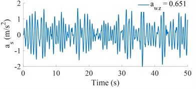
a) Vertical driver’s seat
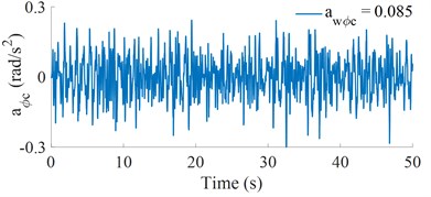
b) Cab pitch acceleration
5.1. Effect of the vehicle suspension parameters on the ride comfort
When the vehicle moves on the road surface, the stiffness and damping of the suspension system not only directly affect the safety such as the stability of the steering, the durability of the components, and the road friendliness, but also affect the ride comfort. Therefore, this paper simulates the model and analyzes the weighted RMS acceleration of the driver’s seat () and cab pitch angle () under the different parameters of the vehicle suspension system.
5.1.1. Effect of the vehicle suspension stiffness
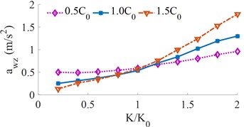
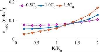
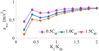
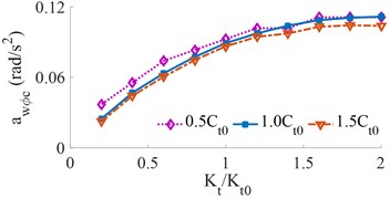
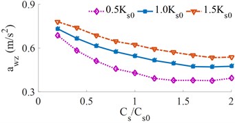
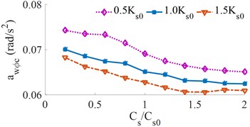
The different stiffness of [0.2, 0.4, …, 2.0]× is selected to simulate the result under three various damping conditions of [0.5, 1.0, 1.5]× when the vehicle moves at the speed 72 km/h on the ISO level B, other conditions remain unchanged. Herein, and . The effect of the different stiffness of the vehicle suspension system on the and values is shown in Fig. 3.
Fig. 3Effect of different vehicle suspension stiffness coefficients on the weighted RMS acceleration
a) Vertical driver’s seat
b) Cab pitch angle
It can be seen that all the weighted RMS acceleration values increase with the increase of the stiffness of the vehicle suspension, thus the ride comfort is reduced. Fig. 3(a) shows that when the stiffness of the vehicle suspension increases by 1.4×, the is strongly increased. Especially when the damping value of the vehicle suspension is small, it has a significant impact on the ride comfort. According to the ISO-2631 standard, the weighted RMS acceleration between 1.25-2.5 m/s2, the driver may feel very uncomfortable. Fig. 3(b) shows that when the stiffness of the vehicle suspension increases by 1.6×, the value increases faster which results in a relatively large shake, especially when the damping coefficient of the vehicle suspension system is low. On the contrary, when the stiffness of the vehicle suspension reduces, both the and values reduce, thus the vehicle ride comfort is improved. However, the reduction of the stiffness of the vehicle suspension system may decrease the vehicle stability and safety. Thus, the stiffness of the vehicle suspension system should be from {0.6 to 1.0}×. In the actual condition, the stiffness of the vehicle suspension system is a difficult change, thus, the air suspensions and its control is researched and developed [5, 11].
5.1.2. Effect of the vehicle suspension damping
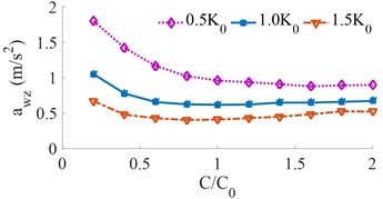
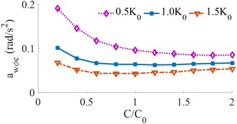
The different damping of [0.2, 0.4, …, 2]× is simulated under three various stiffness values of [0.5, 1.0, 1.5]× and the same simulation condition. The simulation result is shown in Fig. 4.
Fig. 4Effect of different vehicle suspension damping coefficients on the weighted RMS acceleration
a) Vertical driver’s seat
b) Cab pitch angle
The effect of the damping coefficients of the vehicle on the and from Fig. 4 shows that the damping of the vehicle suspensions increases, the weighted RMS acceleration first decreases rapidly and then increases slightly, the vehicle suspension damping has a significantly impact on driver comfort, because the ride comfort of heavy trucks is closely related to road friendliness [2]. When the damping coefficient is increased by 1.4×, the driver’s ride comfort is the maximum. Therefore, the damping coefficient should be also controlled in a range of {1.2 to 1.6}×. This is also a reason that the semi-active vehicle suspension system is strongly researched and developed [18, 19].
5.2. The effect of the wheel stiffness on the ride comfort
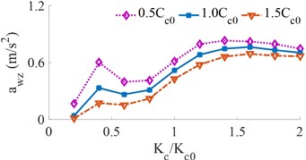
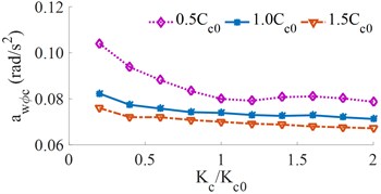
Under the same simulation condition, the effect of the tire stiffness [0.2, 0.4, …, 2.0]× with three various damping conditions of [0.5, 1.0, 1.5]× on the and is also obtained, as shown in Fig. 5.
From Fig. 5, we can see that: (1) With the increase of wheel stiffness, the weighted RMS accelerations increase first and then decrease slightly, which will lead to lower ride comfort; (2) The effect of the change of wheel damping on the ride comfort is small; (3) The smaller the wheel damping, the ride comfort is higher. (4) Increasing the wheel pressure of heavy trucks can not only improve the tire load-bearing performance. But also save fuel consumption and reduce transportation costs [2, 4]. However, when the wheel stiffness is increased by 1.6×, it not only greatly influence the ride comfort but also has a great influence on road friendliness. In order to improve the ride comfort, the use of high-pressure tires should be limited by {0.8 to 1.2}×. In addition, to improve the ride comfort of heavy trucks, the impact of the seat and cab suspension parameters on the ride comfort also need to analyze.
5.3. Effect of the cab suspension parameters on the ride comfort
In a similar simulation and under the same vehicle traveling conditions, the influence of the cab suspension parameters on the and is analyzed below.
5.3.1. Effect of the cab suspension stiffness
With the simulation condition of the cab suspension stiffness [0.2, 0.4, …, 2.0]× and three various damping conditions of [0.5, 1.0, 1.5]×, the results of the and are shown in Fig. 6. The change of the cab suspension stiffness has a significant effect on the driver's ride comfort.
Fig. 5Effect of the different wheel stiffness on the weighted RMS acceleration
a) Vertical driver’s seat
b) Cab pitch angle
It can be seen from Fig. 6(a) that the RMS acceleration of the vertical driver’s seat changes significantly with the increase of the cab suspension stiffness, which leads to a reduction in the ride comfort of the driver. When the stiffness of the cab suspension approaches 0.6×, the RMS acceleration of the vertical driver’s seat is the minimum value. However, it can be seen from Fig. 6(b) that the RMS accelerations of the cab’s pitch angle are significantly enlarged, thus, it can increase the cab shaking and reduce the driver’s ride comfort, so the cab suspension stiffness should be used by {0.6 to 1.0}×. In order to reduce the cab shaking, the heavy truck cab is currently solved by three improved design methods: (1) An auxiliary elastic element in the cab suspension is proposed as a stabilizer bar [13]; (2) Semi-active and active cab suspension damping control [9, 20]; (3) Combined method. The impact of the cab suspension damping on the driver’s ride comfort is analyzed below.
Fig. 6Effect of the different cab suspension stiffness on the weighted RMS acceleration
a) Vertical driver’s seat
b) Cab pitch angle
5.3.2. Effect of the cab suspension damping
Similarly, the relationship between the and for different cab suspension damping changes is shown in Fig. 7.
Fig. 7Effect of the different cabin suspension damping on the weighted RMS acceleration
a) Vertical driver’s seat
b) Cab pitch angle
From Fig. 7, it can be seen that the cabin damping increases, the weighted RMS acceleration decreases, resulting in increased driver’s ride comfort. When the cab damping coefficient is around 1.4×, the weighted RMS acceleration of the vertical driver’s seat is the minimum. It can be seen from Fig. 7(a) that when the stiffness of the cab is relatively small, the damping coefficient greatly influences the weighted RMS acceleration of the vertical driver’s seat, cause of the vibration of the vertical driver’s seat to decrease, and the driver’s ride comfort is greatly improved. However, it can be seen from Fig. 7(b) that the RMS accelerations of the cab’s pitch angle significantly enhances the cab shaking and reduce the ride comfort. Therefore, the damping of the cab suspension should be limited by {1.2 to 1.6}× to improve the driver’s ride comfort.
5.4. Effect of the seat suspension parameters on the ride comfort
The influence of different parameters of the driver’s seat suspension on the and are continuously analyzed under the same conditions of the vehicle.
5.4.1. Effect of the seat suspension stiffness
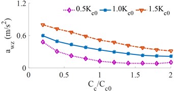
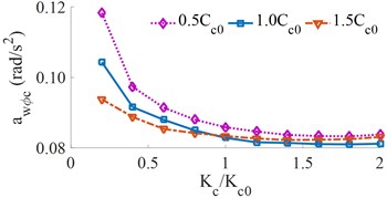
The relationship between the different stiffness of the driver’s seat suspension on the and is shown in Fig. 8. As can be seen from Fig. 8, the change in the seat suspension stiffness has a significant effect on the driver’s ride comfort. It can be seen from Fig. 8(a) that the RMS acceleration of the vertical driver’s seat is significantly changed with the increase of the stiffness of the seat’s suspension, the result is to reduce the driver’s ride comfort. When the stiffness of the seat suspension approaches 0.8×, the RMS acceleration of the vertical driver’s seat reaches a minimum. However, it can be seen from Fig. 8(b) that the RMS acceleration of the cab’s pitch angle is significantly enhanced, which results in a noticeable increase in the cab shaking and reduces the driver’s ride comfort. When the seat suspension stiffness exceeds 1.6×, there is no significance to the driver’s ride comfort. Thus, a range of the stiffness of the driver’s seat suspension in {1.6 to 2.0}× should be applied to improve the driver’s ride comfort.
Fig. 8Effect of the different driver’s seat suspension stiffness on the weighted RMS acceleration
a) Vertical driver’s seat
b) Cab pitch angle
Fig. 9Effect of the different driver’s seat suspension damping on the weighted RMS acceleration
a) Vertical driver’s seat
b) Cab pitch angle
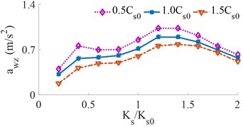
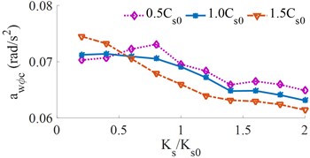
5.4.2. Effect of the seat suspension damping
The relationship between the and for different damper coefficients of the seat’s suspension is shown in Fig. 9. The result shows that the seat damping coefficients increase, the weighted RMS accelerations also decrease, the result is to increase in ride comfort. When the seat suspension damping is approximately 1.6×, the RMS acceleration of the driver’s seat reaches a minimum. It can be seen from Fig. 9(a) that when the stiffness of the seat suspension is small, the driver’s ride comfort is relatively high, however, it can be seen from Fig. 9(b) that the is increased, therefore the cab shaking is increased, which reduces the ride comfort of the driver. To improve the ride comfort and control the cab shaking, the damper coefficients of the seat’s suspension should be controlled by {1.4 to 1.8}×.
6. Conclusions
1) The effect of the stiffness and damping parameters of the vehicle suspension systems are strongly affected the driver’s ride comfort.
2) When increasing the damping parameters and reducing the stiffness parameters of the suspension systems of the seat, cab, vehicle, and wheel, the driver’s seat ride comfort and cab shaking is significantly improved.
3) A range of the optimal parameters of the stiffness and damping values of all the suspension system proposed via the simulation and analysis process for their optimization or control to improve the driver’s seat ride comfort and cab shaking as follows: {0.6 to 1.0}×, {0.8 to 1.2}×, {0.6 to 1.0}×, {1.6 to 2.0}×, {1.2 to 1.6}×, {1.2 to 1.6}×, {1.4 to 1.8}×.
These proposed stiffness and damping values are then optimized and controlled in Part 2 to further improve the vehicle’s ride comfort.
4) This article only considers the ride comfort of the vehicle with different vehicle dynamic parameters. The influences on unsprung mass, sprung mass, road roughness, and the impact of vehicle speed on vehicle ride comfort will be studied and completed further.
References
-
Guglielmino E., Sireteanu T., Stammers C. W., Ghita G., Giudea M. Semi-Active Suspension Control Improved Vehicle Ride and Road Friendliness. Springer Publishing Company, New York, 2008.
-
Zhang H. X., Chen B. C., Zhang T. Z., et al. Relationship between smoothness of a heavy vehicle and its caused damage to pavement. Transactions of the Chinese Society for Agricultural Machinery, Vol. 33, Issue 3, 2002, p. 1-3.
-
Lu S. Optimum design of “road-friendly” vehicle suspension systems subjected to rough pavement surfaces. Applied Mathematical Modelling, Vol. 26, Issue 5, 2002, p. 635-652.
-
Zheng Z. L., Lu P. M. Dynamic load of large trucks acting on pavement. Journal of Chang’an University (Natural Science Edition), Vol. 29, Issue 2, 2009, p. 101-106.
-
Nguyen V. L., Zhang L., et al. Performance analysis of air suspension system of heavy truck with semi-active fuzzy control. Journal of Southeast University, Vol. 33, 2017, p. 159-165.
-
Yong Yang, Weiqun Ren, Liping Chen, Ming Jiang, Yuliang Yang Study on ride comfort of tractor with tandem suspension based on multi-body system dynamics. Applied Mathematical Modelling, Vol. 33, Issue 1, 2009, p. 11-33.
-
Tsampardoukas G., Stammers C. W., et al. Hybrid balance control of a magnetorheological truck suspension. Journal of Sound and Vibration, Vol. 317, Issues 3-5, 2008, p. 514-523.
-
Zhang Z. M., Lu P. M. Optimization method of suspension parameters for articulated vehicle based on ride comfort and road -friendliness. Journal of Traffic and Transportion Engineering, Vol. 9, Issue 5, 2009, p. 49-354.
-
Nguyen, Zhang L., et al. Study of fuzzy control for cab’s isolation system of heavy truck, Vibroengineering Procedia, Vol. 10, 2016, p. 309-314.
-
Sun Z. M., Zhang Z. F., He Y. S., et al. Research on improving the ride comfort of cab for heavy-duty truck. China Mechanical Engineering, Vol. 15, Issue 17, 2004, p. 1584-31586.
-
Nguyen V., Jiao R., Zhang J. Control performance of damping and air spring of heavy truck air suspension system with optimal fuzzy control. International Journal of Vehicle Dynamics, Stability, and NVH, Vol. 4, 2020, p. 179-194.
-
Li P. F., Ma L., He T. M., et al. A simulation study on vibration isolation of cab mount s in a commercial vehicle. Automotive Engineering, Vol. 27, Issue 6, 2005, p. 741-3743.
-
Zhang J. F., He Y. S., Yang H. W. Modification of cab suspension system based on pitch angular acceleration. China Mechanical Engineering, Vol. 23, Issue 18, 2012, p. 2258-2262.
-
Dodds C. J., Robson J. D. The description of road surface roughness. Journal of Sound and Vibration, Vol. 31, Issue 2, 1973, p. 175-183.
-
ISO 8068: Mechanical Vibration-Road Surface Profiles - Reporting of Measured Data, 1995.
-
ISO 2631-1: Mechanical Vibration and Shock- Evaluation of Human Exposure to Whole Body Vibration -Part 1: General Requirements, 1997.
-
Li B. H. 3-D Dynamic Modeling and Simulation of a Multi-Degree of Freedom 3-Axle Rigid Truck. New South Wales, Australia: University of Wollongong, 2006.
-
Nguyen V., Zhang J., Yang X. Low-frequency performance analysis of semi-active cab’s hydraulic mounts of an off-road vibratory roller. Shock and Vibration, Vol. 2019, 2019, p. 1-15.
-
Nguyen V., Nguyen K. Evaluating the effect of the working conditions on the ride comfort and road friendliness of the heavy truck. Vibroengineering Procedia, Vol. 21, 2018, p. 83-88.
-
Chen J., Cao X. L., Wang D. F., et al. Matching and optimization of heavy commercial vehicle. Journal of Jilin University (Engineering and Technology Edition), Vol. 29, Issue 5, 2009, p. 1125-1127.
Cited by
About this article

This research was supported by Open Fund Project of Hubei Key Laboratory of Intelligent Transportation Technology and Device, Hubei Polytechnic University, China (No. 2020XY105) and Talent Introduction Fund Project of Hubei Polytechnic University (No. 19XJK17R).
