Abstract
To control the cab shaking of the vibratory roller, an auxiliary damping mount (ADM) used for the cab isolation system in horizontal direction is proposed. Based on the off-road vibratory roller dynamic model under the conditions of the vehicle moving and compacting, the damping characteristic and installation position of the ADM for reducing vibration of the cab are respectively analyzed. The weighted root-mean-square (RMS) of acceleration responses of the vertical driver’s seat and pitching cab angle are chosen as the objective functions. The research results show the cab shaking is greatly reduced by using the ADM in comparison without ADM. Additionally, the drive’s seat vibration is also significantly decreased under both the compacting and moving conditions of the vibratory roller.
1. Introduction
Due to the commercial competition of construction vehicles, especially vibratory rollers, the requirements for vibratory rollers are becoming more and more stringent. The vibratory roller was not only required to improve the compression efficiency but also to ensure the ride comfort of the cab and operator [1-4]. In the working process of the vehicle, due to the vertical excitation force of the vibrator drum was high, and vibratory rollers mainly worked on the sandy terrains with the low-density, therefore, the vertical vibration of the driver’s seat and the cab shaking angle were greatly affected, so the driver’s feel was very uncomfortable [1, 5]. Consequently, the study and improvement of the cab isolation system had been interested by many researchers.
Based on the traditional rubber mount of the vibratory roller cab [1, 4], the hydraulic isolation mount used for engine isolation system [6-8] were studied and applied for the vibratory rollers to improve the cab ride comfort [1, 9-10]. The results showed that the cab ride comfort with the hydraulic mount was better than the traditional rubber mount. However, the vertical and pitching vibrations of the driver’s seat and cab were very high under the condition of the vehicle traveling and compacting. The parameter of the hydraulic mount was then optimized based on the Genetic algorithm [1, 11]. To further improve the ride quality of the vibratory rollers, the cab hydraulic mounts were controlled. The PID-Fuzzy control was applied to control the cab ride comfort in the frequency domain [12], in the time domain [13], and in both the frequency and time domain [5, 11]. The research results indicated that both the vertical and pitching vibrations of the cab were strongly reduced by the semi-active cab hydraulic mounts under various operating condition of the vehicle in the low-frequency excitation range. However, the structure of the PID-Fuzzy control is complicated and its cost is high, thus, it could be difficult to apply for the vibratory roller cab in the actual condition.
With a more practical method of controlling the cab shaking and improving the vibratory roller ride quality, in this study, based on the non-linear dynamic model of the off-road vibratory roller in Ref. [13], a horizontal auxiliary damping mount used for the cab isolation system is proposed to control the cab shaking of the vibratory roller. The installation position of the ADM and its damping characteristic for decreasing vibration of the cab are respectively simulated. The weighted root-mean-square (RMS) of acceleration responses of the vertical driver’s seat and pitching cab angle are chosen as the objective functions under the operating condition of the vehicle moving and compacting. The objective of this study is to control the cab shaking and to reduce the vibration of the driver’s seat.
2. Vibratory roller dynamic model with the ADM
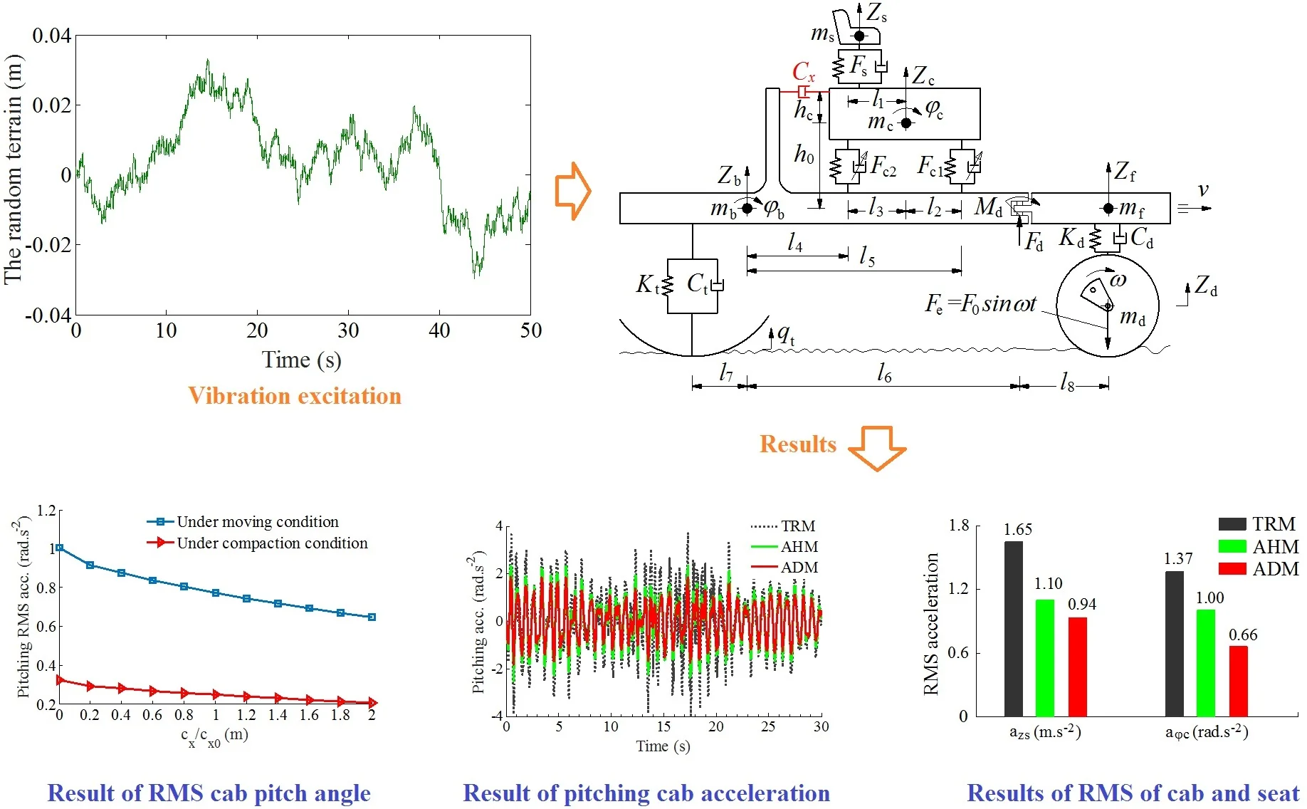
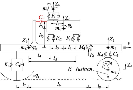
A non-linear dynamic model of an off-road vibratory roller with 7DOF is established based on its actual structure. An auxiliary damping mount is added the cab isolation system in the horizontal direction to control the cab shaking. The lumped parameter model of the vehicle is shown in Fig. 1, where the vertical displacements of the driver’s seat, cab, front/rear-frames, and rigid drum are defined by , , , and , respectively, while the angular displacements of the cab and frame-rear are defined by and ; the mass of the driver’s seat, cab, front/rear-frames, and rigid drum are also defined by , , , and , respectively; and are the vertical dynamic forces of the vibration isolation systems of the seat and cab; is the random terrain surface and is the vibratory roller’s distances ( 1-8); the stiffness and damping coefficients of the drum rubber mount and wheel are defined by , , and , , respectively.
Fig. 1Dynamic model of the vibratory roller using a horizontal auxiliary damping mount
The vibration equations describing the dynamics of the vehicle and the cab are written by:
where and
The driver’s seat suspension is used by a spring with its stiffness coefficient and a damper mount with its damping coefficient , the dynamic force of the driver’s seat suspension is then given by:
According to the cab isolation system of the vibratory roller [1], the cab isolation system is equipped with the traditional rubber mounts (TRM) including the high stiffness and low damping coefficients and of the TRM. In order to improve the cab’s ride comfort, the TRM is added a hydraulic mounts (AHM) with the high damping coefficients [5-6, 9]. The force equations of the cab isolation mounts are determined as follows:
With the TRM:
With the TRM added by the AHM:
With the ADM:
The cab ride comfort is significantly improved with the TRM added by the AHM, however, the cab shaking angle is still high under the various operating conditions [1, 5], this study proposes to add an auxiliary damping mount (ADM) with the damping coefficient in horizontal direction into the cab isolation system, as seen in Fig. 1. The dynamic force of the ADM is given as follows:
where the force of in the horizontal direction acts to create counter-torques of and to reduce the shaking angles of the cab and rear vehicle frame.
The excitation forces of the wheel and vibrator drum are determined by:
where the road surface excitation at the wheel and the drum excitation are determined in Section 3.
By replacing the dynamic force equations from Eqs. (2) to (8) into Eq. (1), the dynamic equations of the vehicle is then solved.
3. Vibration excitation of the vibratory roller
To determine the vertical excitation forces of the vehicle at the wheel and drum under the traveling and compacting conditions of the vibratory roller, two cases of vibration excitation are given as follows:
3.1. Vibration excitation of the wheel on the terrain surface
The ride comfort of vibratory rollers is greatly affected not only by the excitation of the drum-deformable terrain interaction but also by the rough terrain surfaces [1]. The random terrain surface is calculated based on the power spectral density (PSD) in the frequency domain, and the spatial PSD of the terrain surface profile is described by the spatial frequency function (cycle/m) [16, 17]. Based on the ISO proposal [18] over the different spatial frequency ranges, the spectral density of the terrain surface is thus written as follows:
where is the spectral density of the random terrain with the reference spatial frequency (cycle/m).
Particularly, it is assumed the vibratory rollers move with a constant velocity v0, the terrain surface roughness in the time domain can be performed as follows [12, 14]:
where is the number of intervals; is the surface roughness coefficient and is space frequency; and is the length of road segment; is the fundamental temporal frequency. is a random phase uniformly distributed from 0 to 2.
According to the research result of Refs. [1, 5, 19], it is extended the spectral density ranges for the unpaved terrain classifications apart from the traditional asphalt road classifications, including the classification ranges of good, medium, poor and very poor, as listed in Table 1, and the terrain surface roughness is yielded by choosing a value in the spectral density ranges.
Table 1The parameters of the unpaved terrain classification
Classification | Good | Medium | Poor | Very poor |
2.25 | 2.25 | 2.14 | 2.14 | |
×10-6(m3/cyc) | 199.8 | 973.9 | 3782.5 | 102,416 |
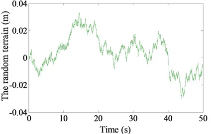
In this study, to create an terrain surface roughness for the vibratory roller closing to the actual terrain condition, the parameters of a poor rough terrain surface of 1.67 m s-1, 84 m, 0.005 s, 2.14, and 3782.5×10-6 m3/cycle are used to simulate the terrain surface roughness in the time domain, as shown in Fig. 2, and it is used to determine the vibration excitation of the terrain on the wheel.
Fig. 2Vibration excitation of a poor terrain surface
3.2. Vibration excitation of the drum on the elastor-plastic soil
Based on the research result of the vertical excitation force between the vibrator drum-elastor plastic soil interaction in Refs. [10-12], the vertical vibration excitation force of the drum was given as follows:
where and are the plasticity factor and damping ratio of elastor-plastic terrain; is the damping coefficient of the terrain; and are the elastic and plastic stiffness of the terrain.
By combining Eqs. (8) and (11), vibration excitation force of the drum is then determined.
Table 2Parameters of the vibratory roller
Parameter | Value | Parameter | Value | Parameter | Value | Parameter | Value |
/ kg | 85 | / m | 0.1 | / m | 0.6 | / Ns m-1 | 1.2×10² |
/ kg | 891 | / m | 0.383 | / m | 1.5 | / Ns m-1 | 218×102 |
/ kg | 2822 | / m | 0.1 | / Nm-1 | 1.2×10⁴ | / Ns m-1 | 29×102 |
/ kg | 4464 | / m | 0.524 | / Nm-1 | 9.1×10⁵ | / Ns2 m-2 | 20×103 |
/ kg | 4378 | / m | 0.136 | / Nm-1 | 1.2×10⁵ | / Ns2 m-2 | 4.5×10³ |
/ kgm2 | 523 | / m | 0.76 | / Nm-1 | 3.9×10⁶ | / Ns m-1 | 2.9×10³ |
/ kgm2 | 1.2×10⁴ | / m | 0.9 | / Nm-1 | 0.5×10⁶ | / Ns m-1 | 4.0×10³ |
4. Result and discussion
To evaluate the performance of the damping parameter and installation position of the ADM for reducing vibration of the cab, especially the cab shaking, the weighted RMS accelerations of the vertical driver’s seat and pitching cab angle calculated in [9, 14-15] are chosen as the objective functions as follows:
where and are the acceleration responses of the vertical driver’s seat and pitching cab angle in the simulation time domain.
Based on the parameters of the vibratory roller, as listed in Table 2, two simulation conditions of the vehicle are presented as follows:
4.1. Under the moving condition of the vehicle
When the vibratory roller moves into the workshop, the vehicle speed of 6 km/h and the poor road surface of off-road terrain, as shown in Fig. 2, are chosen to simulate and analyze the performance of the ADM.
The performance of the ADM for reducing the cab vibration could be influenced by both the installation position and damping coefficient of the ADM. Therefore, the installation positions of {0, 0.05, 0.1, 0.15, 0.2, 0.25, 0.3, 0.35, 0.4} (m) with the reference parameter of 1.5×10³ Ns/m [10] are simulated to evaluate the influence of of the ADM on the cab shaking. The simulation results are plotted in Fig. 3. The results show that the vertical RMS acceleration of the driver’s seat is insignificantly reduced when increasing the (Fig. 3(a)), however, the RMS acceleration of the pitching cab angle is strongly reduced (Fig. 3(b). This is due to both the counter-torques of and are increased by increasing the , especially at 0.4 m.
Also, the influence of the damping coefficients of the ADM on the cab shaking is concerned. The damping coefficients of {0, 0.2, 0.4, 0.6, 0.8, 1.0, 1.2, 1.4, 1.6, 1.8, 2.0}× Ns/m with 0.1 m are then simulated to evaluate the performance of the ADM on the cab shaking. The simulation results are shown in Fig. 4. Observing the results in Figs. 4(a) and (b), both the RMS values of the driver’s seat and pitching cab angle are quickly decreased by increasing the damping value of the ADM, particularly at 2.0× Ns/m. This is due to the damping force of in the horizontal direction which creates counter-torques of and is increased with increasing .
Fig. 3The influence of the installation position of the ADM
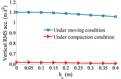
a) Driver’s seat in the vertical direction
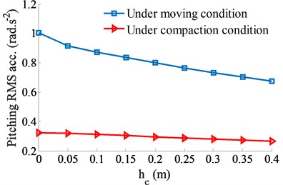
b) Cab angle in the pitching direction
Fig. 4The influence of the damping coefficient of the ADM
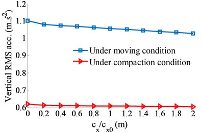
a) Driver’s seat in the vertical direction
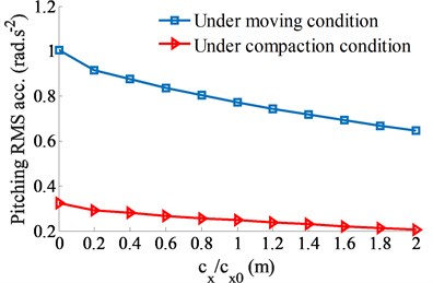
b) Cab angle in the pitching direction
Consequently, based on the analysis results of the ADM added in the cab isolation system in the horizontal direction, the RMS value of the driver’s seat is significantly reduced while the RMS value of the pitching cab angle is greatly increased. It implies that the ADM added the cab in the horizontal direction could greatly improve the cab shaking.
Fig. 5Performance of the ADM under the moving condition of the vehicle
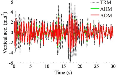
a) Driver’s seat in the vertical direction
b) Cab angle in the pitching direction
With the installation position of 0.4 m and damping coefficient of 2.0× Ns/m, the acceleration responses and RMS values of the driver’s seat and pitching cab angle are compared with the TRM and AHM. The simulation results are plotted in Figs. 5 and 6.
The acceleration responses in Figs. 5(a) and (b) show that the cab isolation mount added the horizontal auxiliary damping mount could improve the cab ride comfort better than both the TRM and AHM without the ADM, especially reducing the pitching angle of the cab. Additionally, by comparing the RMS values in Fig. 6, the RMS value of the driver’s seat and pitching cab angle with using the ADM is reduced by 14.5 % and 34.0 % in comparison without the ADM. Therefore, the ADM not only greatly improves the cab shaking, but also can reduce the vertical vibration of the driver’s seat under the moving condition of the vehicle.
Fig. 6RMS acceleration responses of the seat and cab under the moving condition
4.2. Under the compaction condition of the vehicle
The existed studies show that the pitching cab angle is greatly affected when the vibratory roller moves and compacts on the sandy ground with its low-density under the excitation frequency 28 Hz of the vibrator drum [1, 5, 11]. Therefore, to evaluate the performance of the ADM, assuming that the vibratory roller moves and compacts at a very slow of 3 km/h on the sandy ground with low-density under the excitation frequency 28 Hz of the vibrator drum. The numerical value of the sandy ground with low-density is listed in Ref. [12].
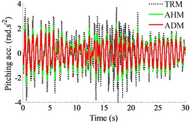
Fig. 7Performance of the ADM under the compaction condition of the vehicle
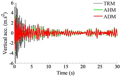
a) Driver’s seat in the vertical direction
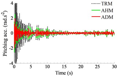
b) Cab angle in the pitching direction
Similarly, the performance of the ADM for reducing the cab shaking is also analyzed under two cases of the and . The installation positions of {0, 0.05, 0.1, 0.15, 0.2, 0.25, 0.3, 0.35, 0.4} m with the reference parameter of 1.5×10³ Ns/m [10] and damping coefficients of {0, 0.2, 0.4, 0.6, 0.8, 1.0, 1.2, 1.4, 1.6, 1.8, 2.0}× Ns/m with 0.1 m are analyzed under the compaction condition of the vehicle, respectively. The simulation results are shown in the same Figs. 3 and 4. Similar to the case of moving vehicle, the RMS value of the driver’s seat is slightly reduced when increasing both the values of and , as shown in Figs. 3(a) and 4(a), while the RMS value of the pitching cab angle is greatly reduced when increasing both this values, as plotted in Figs. 3(b) and 4(b). This is also due to both the counter-torques of and are increased when increasing both the value of and . especially at 0.4 m and 2.0× Ns/m.
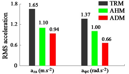
Fig. 8RMS acceleration responses of the seat and cab under the compaction condition
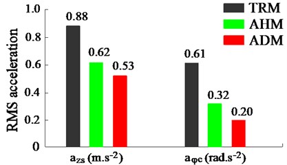
Also at the installation position of 0.4 m and damping coefficient of 2.0× Ns/m, both the acceleration response and RMS value of the driver’s seat and pitching cab angle are simulated and compared with both the TRM and AHM of the cab. The results are shown in Figs. 7 and 8. Observing both Figs. 7(a) and (b), the result indicates that the acceleration responses of the driver’s seat and pitching cab angle with the ADM are smaller than both the TRM and AHM without the ADM. Besides, their RMS values calculated in Fig. 8 also emphasize that both the RMS value of the driver’s seat and pitching cab angle with the ADM is reduced by 14.5 % and 37.5 % in comparison without the ADM. Therefore, the ADM also greatly improves the cab shaking and the vertical vibration of the driver’s seat under the compaction condition of the vehicle.
5. Conclusions
Based on the results of existed researches on improving the cab ride comfort the off-road vibratory roller [1, 5, 10-11], an issue that has not yet been thoroughly resolved is that the cab shaking is still high under the vehicle’s working conditions. In this study, a horizontal auxiliary damping mount for the cab isolation system is proposed to further improve the cab shaking. The main conclusions can be summarized as follows:
The cab isolation system added by the ADM not only great improves the cab shaking, but also significantly reduces the vertical vibration of the driver’s seat under the various operation condition of the vehicle. Particularly, the cab shaking with the cab isolation system using the ADM is reduced by 34.0 % and 37.5 % in comparison without the ADM under the moving condition and the compaction condition of the off-road vibratory roller.
In the existed researches, the TRM of the cab was replaced by using the HM [1, 9]. The HM was then optimized [10] and controlled by using the optimal PID-Fuzzy control [5, 11-13]. The results indicate that the cab shaking has been greatly controlled. However, it is very difficult to apply these research results for the vibratory roller cab in the actual condition due to the high cost of the controller, which can also make the cost of vibratory rollers also increase. The results of this study also show that the cab shaking has been greatly reduced by using the ADM, while the structure of the ADM is relatively simple, and its application to the cab isolation system to improve the ride comfort is entirely possible.
References
-
Nguyen V., Zhang J., et al. Vibration analysis and modeling of an off-road vibratory roller equipped with three different cab’s isolation mounts. Shock and Vibration, Vol. 2018, 2018, p. 8527574.
-
Paul J., Michael A. Capturing nonlinear vibratory roller compactor behavior through lumped parameter modeling. Journal of Engineering Mechanics, Vol. 134, 2008, p. 684-693.
-
Li J., Zhang Z., et al. Dynamic characteristics of the vibratory roller test-bed vibration isolation system: simulation and experiment. Journal of Terramechanics, Vol. 56, 2014, p. 139-156.
-
Adam D., Kopf F. Theoretical analysis of dynamically loaded soils. Proceedings of the European Workshop Compaction of Soils and Granular Materials, Paris, France, 2000, p. 207-217.
-
Nguyen V., Zhang J., Yang X. Low-frequency performance analysis of semi-active cab’s hydraulic mounts of an off-road vibratory roller. Shock and Vibration, Vol. 2019, 2019, p. 8725382.
-
Lee P., Vogt J., Han S. Application of hydraulic body mounts to reduce the freeway hop shake of pickup truck. SAE Technical Paper 2009-01-2126, 2009, https://doi.org/10.4271/2009-01-2126.
-
Wang M., et al. A novel design of semi-active hydraulic mount with wide-band tunable notch frequency. Journal of Vibration and Control, Vol. 333, 2014, p. 2196-2211.
-
Marzbani H., Jazar R., et al. Hydraulic engine mounts: a survey. Journal of Vibration and Control, Vol. 20, 2010, p. 1439-1463.
-
Nguyen V., Nguyen K. Enhancing the ride comfort of the off-road vibratory roller cab by adding damper hydraulic mount. Vibroengineering Procedia, Vol. 21, 2018, p. 89-95.
-
Nguyen V., Zhang J., et al. Ride quality evaluation of the soil compactor cab supplemented the auxiliary hydraulic mounts via simulation and experiment. Journal of Southeast University (English Edition), Vol. 35, Issue 3, 2019, p. 273-280.
-
Nguyen V., Zhang J., et al. Performance analysis of semi-active hydraulic system of the off-road vibratory roller cab using optimal fuzzy-PID control. Journal of Southeast University (English Edition), Vol. 35, Issue 4, 2019, p. 399-407.
-
Nguyen V., Jiao R., et al. Performance of PID-Fuzzy control for cab isolation mounts of soil compactors. Journal of Mathematical Models in Engineering, Vol. 5, Issue 4, 2019, p. 137-145.
-
Jiao R., Nguyen V. Improving ride comfort for vibratory roller utilizing semi-active hydraulic cab mounts with control optimization. Vibroengineering Procedia, Vol. 28, 2019, p. 75-80.
-
Nguyen V., Zhang J., Jiao R., et al. Effect of the off-road terrains on the ride comfort of construction vehicles. Journal of Southeast University (English Edition), Vol. 35, Issue 2, 2019, p. 191-197.
-
Nguyen V., Zhang J., Le Q., et al. Performance analysis of air suspension of heavy truck with semi-active fuzzy control. Journal of Southeast University (English Edition), Vol. 33, Issue 2, 2017, p. 159-165.
-
Wong J. Theory of Ground Vehicles. John Wiley and Sons Inc, New York, 2001.
-
Robson J. Road surface description and vehicle response. International Journal of Vehicle Design, Vol. 1, Issue 1, 1979, p. 25-35.
-
ISO/TC108/SC2/WG4 N57, Reporting Vehicle Road Surface Irregularities. International Organization for Standardization, 1982.
-
Mitschke M. Dynamik Der Kraftfahrzeuge. Springer-Verlag, Berlin, 1972.
Cited by
About this article

This study is supported by Hubei Polytechnic University Teaching and Research Projects [No. 19XJK17R].
