Abstract
The structural vibration of the center impression cylinder in the flexographic printing machine will bring about production quality problems such as printing ghosts. To this problem, it become an important method to analysis the dynamic characteristics of the center impression cylinder. In this paper, a three-dimensional structural model of the central impression cylinder is established, and builds the dynamic model in finite element software. The vibration modes of the central impression cylinder were studied in the simple-supported system at both ends of the static impression cylinder. In view of the real existence of the rotating dynamic load, the evolution law of the natural frequency and mode shape of the cylinder with the rotating dynamic load is discussed. It is found that as the rotation speed increases, the natural frequency undergoes two steps, and the natural frequency after each step will keep continuity with the high first-order natural frequency, and the modal shape is the same as the high-order original mode. Then, the mode shape is continuously changed, not have a step.
Highlights
- The dynamic model of printing cylinder in the simple-supported system at both ends is built using finite element method.
- Discussed the evolution law of the natural frequency and mode shape of the cylinder with the rotating dynamic.
- Revealed the step of natural frequency on the central impression cylinder and the continuously variation characteristic of mode shape.
1. Introduction
When the speed of offset press production equipment reaches 12,000 sheets per hour or more, the structural vibration in the equipment will become severe, and causes the decrease to printing precision [1-3]. Hence, suppressing the vibration of the printing cylinder and improving the stable printing speed will be an important problems to be overcome [4-6].
The most important part of a printing equipment is the impression cylinder, whose structural vibration affects the accuracy of paper transfer and the registration accuracy of printing sheet [7-9]. Therefore, it is necessary to ensure that the impression cylinder of the equipment is stably during operating the equipment. Because the main vibration source of the printing equipment is the impression cylinder, the vibration characteristics of the printing cylinder is studied in this paper. In a printing equipment, the printing unit consists of an impression cylinder, a plate cylinder and a blanket cylinder. In this operation mode, the vibration of the impression cylinder will cause other parts to resonate [10, 11]. Suppressing the vibration of the cylinder can improve the working performance of the printing machine and reduce the occurrence of printing faults [12-14].
Due to the structural particularity, the impression cylinder has uneven mass distribution, which causes violent vibration in high-speed printing production, resulting in printing fault. Researchers have made many achievements in studying the vibration of the cylinder. Bartlett et al. established the relevant dynamic model based on the actual impression cylinder, which can analyze the vibration characteristics of the impression cylinder in two special working steps of acceleration and deceleration [1]. Hermanski et al. developed an algorithm and applied it to solve the torsional vibration problem of the impression cylinder, which improved the printing quality and reduced the influence of vibration on the printed product [4]. In 1997, Yamaguchi et al. proposed a method of installing a bumper that absorbs a portion of the vibrational energy, reduces the amplitude, and cushions the impact when the cylinder is affected by the impact [15]. In 2006, Yang Xinyan et al. used finite element analysis to study a certain type of offset printing cylinder [16], and used Ansys simulation software to establish a finite element meshing model, and perform static analysis to obtain the deflection and deformation of the cylinder under different vibration frequencies. In 2009, Deng et al. used the Anasys-based optimization design to build a cylinder model, analyze the structural problems similar to the impression cylinder, and solve the vibration caused by the structure [12]. These research reports reveal the vibration characteristic of printing mechanism no running. However, the vibration characteristic of printing mechanism with rotating dynamic load is not studied up to now. Therefore, this work will be carried out in this paper.
In this paper, a three-dimensional structural model of the central impression cylinder is established, and builds the dynamic characteristics analysis model in finite element software, details is in Section 2. The vibration modes of the central impression cylinder were studied in the simple-supported system at both ends of the static impression cylinder in Section 3.1. The evolution law of the natural frequency and mode shape of the cylinder with the rotating dynamic load is discussed in Section 3.2. Conclusions are listed in Chapter 4.
2. Impression cylinder model
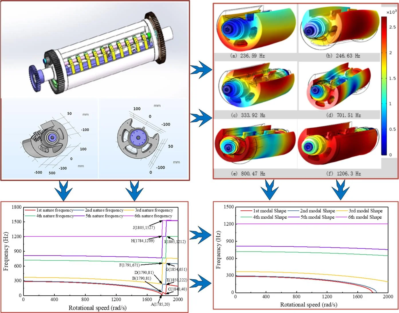
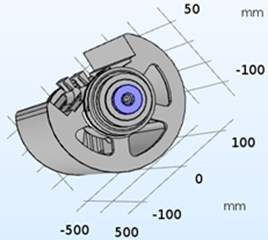
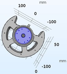
Offset printing press is the most important printing equipment in the printing industry, with relatively high stability and fast printing speed. For multi-color printing, the dynamic characteristics of the offset printing cylinder directly affects the print quality of multi-color registration print. The offset printing press generally contains multiple printing units, and each printing unit has three cylinders, which are an impression cylinder, a rubber cylinder and a plate cylinder, and the three cylinders structures are basically similar. The cylinder is composed of three parts: the cylinder pillow, the shaft neck and the cylinder body. The model diagram is shown in Fig. 1. In this study, a simple support constraint is added to the axial ends of the cylinder to simulate the support constraint of the bearing seat on the center cylinder, as shown in Fig. 2.
Fig. 13D model of the roller
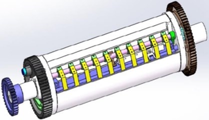
Fig. 2Roller constraint addition
The impression cylinder material is made of carbon structural steel with an elastic modulus of 2.10×10¹¹ MPa, a density of 7850 kg/m3and a Poisson’s ratio of 0.3. For finite element simulation in COMSOL Multiphysics, the 3D model of cylinder is invoked into COMSOL, and generating mesh entirely automatically with unstructured tetrahedral mesh and mesh smoothing algorithm, the total number of grid is 115622.
3. Cylinder modal analysis
3.1. Static vibration characteristics of central impression cylinder
In the printing process, resonance will occur and the vibration amplitude will be large when the load excitation frequency of the cylinder be close to the characteristic frequency of the cylinder. The resonance will damage the impression cylinder structure. Therefore, resonance should be avoided as much as possible in print. Then, the modal analysis and natural frequency calculation of the cylinder becomes an important approach to study the cylinder resonance. In this paper, the natural frequency and mode shape of the center impression cylinder are calculated by finite element software (COMSOL Multiphysics). The calculation results of the first six natural frequencies of the center impression cylinder are shown in Table 1. The natural frequency band is 0-1206.3 Hz, the minimum frequency is 236.59 Hz, and the maximum frequency is 1206.30 Hz. The first two natural frequency spacings are at least 10.04 Hz, which is the main frequency segment of vibration control.
Fig. 4Modal shape of the center impression cylinder
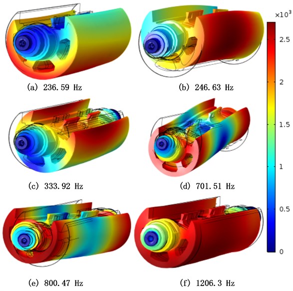
The vibration mode corresponding to the first six natural frequencies is shown in Fig. 4. Fig. 4(a) shows the first-order natural frequency corresponding to the mode shape, and the center impression cylinder is reverse-clocked to vibrate along the rotation axis. The second-order natural frequency corresponding to the mode shape is the upper arch vibration of the middle impression cylinder, and the mode shape is shown in Fig. 4(b). Fig. 4(c) shows the third-order natural frequency corresponding to the mode shape, and the middle of the intermediate impression cylinder vibrates in the left direction. The fourth and fifth mode shapes are shown in Fig. 4(d) and 4(e), and the central impression cylinders exhibit vertical S-type bending vibration and horizontal S-type bending vibration, respectively. The sixth-order mode shape is axial vibration, and its mode shape is shown in Fig. 4(f).
Table 1Natural frequency of the drum body
Modal step | Natural frequency (Hz) |
1 | 236.59 |
2 | 246.63 |
3 | 333.92 |
4 | 701.51 |
5 | 800.47 |
6 | 1206.3 |
3.2. Vibration characteristics of central impression cylinder under rotating load
In engineering, the modal analysis focus on modal analysis of the static model. For the rotational structure, dynamic load and gyroscopic force of rotating structure will change the modal characteristics of the structure. The static modal analysis will be given the structure vibration characteristics, the modal analysis of rotating structure with dynamic load analysis will introduce the influence rotating dynamic load, rotation inertia force and gyroscopic force on the modal characteristics. Therefore, on the basis of the analysis of the static modal analysis, the modal characteristic of rotating structure with dynamic load is studied in this paper. the mode shape and natural frequency of the central impression cylinder under different speeds are calculated by sweep arithmetic. The calculation results are shown in Fig. 5.
Fig. 5Natural frequency of the center impression cylinder at different speeds
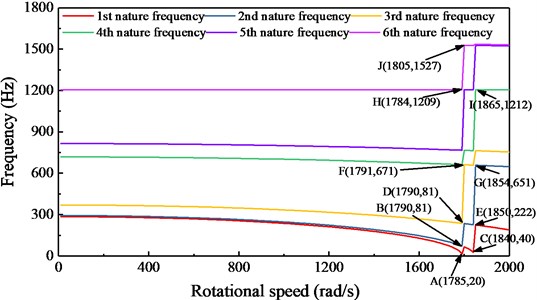
The natural frequency of the center impression cylinder under different speeds is shown in Fig. 5. Between 0 Hz and 1785 Hz, the natural frequency of the central impression cylinder gradually decreases with increasing rotational speed, and the lower the order of the natural frequency, the smaller the reduction of the natural frequency. Between 1785 Hz and 1880 Hz, the natural frequency of the central impression cylinder takes two steps, and after each step, the frequency corresponds to the high first order natural frequency.
During the natural frequency step change of the center impression cylinder, the change of the vibration characteristics is not outstanding. To further illustrate this phenomenon, the vibration modes at the natural frequency step are studied. 10 key points of the step change are marked in Fig. 5. The vibration modes of the 10 key points are calculated, and the results are shown in Fig. 6. Fig. 6(a) is the vibration mode of the key point A, the clockwise torsional vibration along the central axis, the same as the static first-order vibration mode. Fig. 6(b) and Fig. 6(c) show the vibration modes of the key points B and C. The vibration modes of two key points are the same, and model displacement is in the middle arch along the missing portion of the center impression cylinder. Fig. 6(d) and Fig. 6(e) show the vibration modes of the key points D and E. The vibration modes of the two key points are the same, and both are transversely curved and vibrated along the middle of the center impression cylinder. Corresponds to the static third-order vibration mode. Fig. 6(f) and Fig. 6(g) show the vibration modes of the key points F and G. The vibration modes of the two key points are the same, and both are vertical S-shaped bending vibrations along the center impression cylinder. Corresponds to the static fourth-order vibration mode. Fig. 6(h) and Fig. 6(i) show the vibration modes of the key points H and I. The vibration modes of the two key points are the same, and axial vibrations along the center impression cylinder. Fig. 6(j) is the vibration mode of the key point J, which is a vertical M-shaped bending vibration along the center impression cylinder.
Fig. 6Modal shape of the central impression cylinder at different speeds
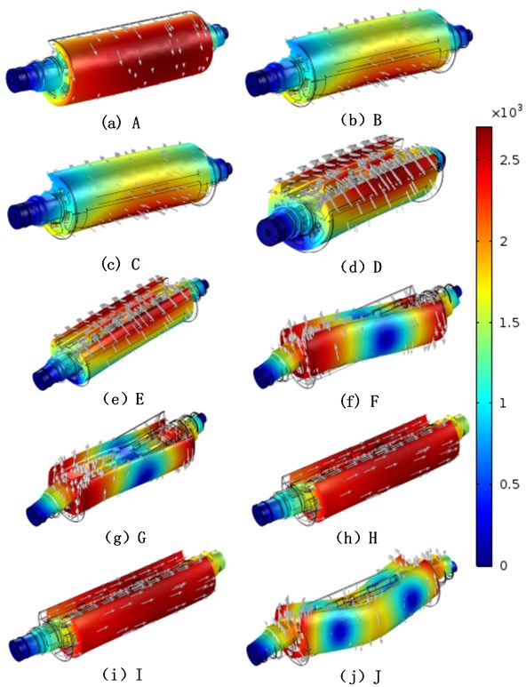
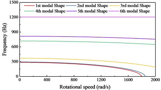
Based on the results, it is found that the mode shape of the natural frequency is the same as that of the first-order original mode. It can be seen that the natural frequency of the central impression cylinder has two steps, the natural frequency corresponding to the mode shape is continuously changed and no step occurs. When at different speeds, the natural frequency corresponding to the center impression cylinder can be plotted as a mode-specific frequency diagram as shown in Fig. 7.
Fig. 7Modal shape of the center impression cylinder with rotating dynamic load
4. Conclusions
In this paper, a three-dimensional structural model is established for the center of the flexographic printing press. The finite element software was used to build a dynamic model of the impression cylinder. The vibration characteristics of the simply supported system at both ends of the static impression cylinder were analyzed by using the model, and the various model shape of the central impression cylinder were compared. Furthermore, for the rotational dynamic load of the central impression cylinder, the evolution law of the natural frequency and mode shape of the cylinder under the dynamic load is analyzed. The conclusions are as follows:
1) As the rotation frequency increases, the natural frequency undergoes two steps, and the natural frequency after each step is adapted to the high first-order natural frequency.
2) After the natural frequency has a step, the modal shape is the same as the high-order original mode. That is, the natural frequency corresponding to the mode shape is continuously changed, and the mode does not have a step.
References
-
Bian Y., Gao Z., Hu J., Fan M. A semi-active control method for decreasing longitudinal torsional vibration of vehicle engine system: theory and experiments. Journal of Sound and Vibration, Vol. 439, 2019, p. 413-433.
-
Komatsu H., Yoshida T., Takagi S., Shen T. Improvement of Printing Accuracy via Web Handling Control in Multi-Colors Printing Machines. China Printing and Packaging Study, 2009.
-
Kulikov G. B. Diagnosing causes of increased vibration of printing units of tower rotary printing presses. Journal of Machinery Manufacture and Reliability, Vol. 37, 2008, p. 391-396.
-
Kim C. H., Jo J., Lee S.-H. Design of roll-to-roll printing equipment with multiple printing methods for multi-layer printing. Review of Scientific Instruments, Vol. 83, 2012, p. 065001.
-
Vanhonacker P. Differential and difference sensitivities of natural frequencies and mode shapes of mechanical structures. AIAA Journal, Vol. 18, 1980, p. 1511-1514.
-
Palomo Guerrero D., Jiménez Espadafor F.-J. Torsional system dynamics of low speed diesel engines based on instantaneous torque: Application to engine diagnosis. Mechanical Systems and Signal Processing, Vol. 116, 2019, p. 858-878.
-
Pyryev Y., Krzyzkowski J. Parametric vibrations in offset printing units. Theoretical and Applied Mechanics Letters, Vol. 2, 2012, p. 043011.
-
Senjanović I., Hadžić N., Murawski L., Vladimir N., et al. Analytical procedures for torsional vibration analysis of ship power transmission system. Engineering Structures, Vol. 178, 2019, p. 227-244.
-
Tg C. M., Rajala P., Toiviainen M., Juuti M., Gane P. A. C. Combining simulation and on-line measurements to determine moisture transport dynamics throughout the heatset offset printing process. Applied Thermal Engineering, Vol. 50, 2013, p. 1021-1028.
-
Tg C.-M., Toiviainen M., Juuti M., Gane P. A. C. Dynamic analysis of temporal moisture profiles in heatset printing studied with near-infrared spectroscopy. Measurement Science and Technology, Vol. 21, 2010, p. 105602.
-
Wang Y. M., Xu W. C., Wu S. Q., Chai C. W., Liu X., Wang S. H. Research on torsional vibration modelling and control of printing cylinder based on particle swarm optimization. IOP Conference Series: Materials Science and Engineering, Vol. 339, 2018, p. 012031.
-
Tucker W. R., Wang C. On the effective control of torsional vibrations in drilling systems. Journal of Sound and Vibration, Vol. 224, 1999, p. 101-122.
-
Yao J. P. Modal analysis of the centre impression cylinder. Mechanical Research and Application, 2014.
-
Yao Y., Zhao L. Geometric error analysis on OLED units’ three-dimensional microstructure in ink-jet printing process. IEEE 3rd International Conference on Communication Software and Networks, 2011.
-
Kammer D. C., Tinker M. L. Optimal placement of triaxial accelerometers for modal vibration tests. Mechanical Systems and Signal Processing, Vol. 18, 2004, p. 29-41.
-
Yang X. The finite element analysis of impressing cylinder on offset press. Xi’an University of Technology, 2006.
About this article

The work described in this paper was supported by National Natural Science Foundation of China (Project No. 51905420), Natural Science Foundation of Shaanxi Provincial Department of Education (Project No. 19JK0582), Technology Planning Project of Xi’an (Project No. 2019217814GXRC014CG015-GXYD14.19), Key Technology Research and Development Program of Shaanxi (Project No. 2019ZDLGY14-08) and Natural Science Research Program of Shaanxi (Project No. 2019JM-059 and 2018JM5014).
