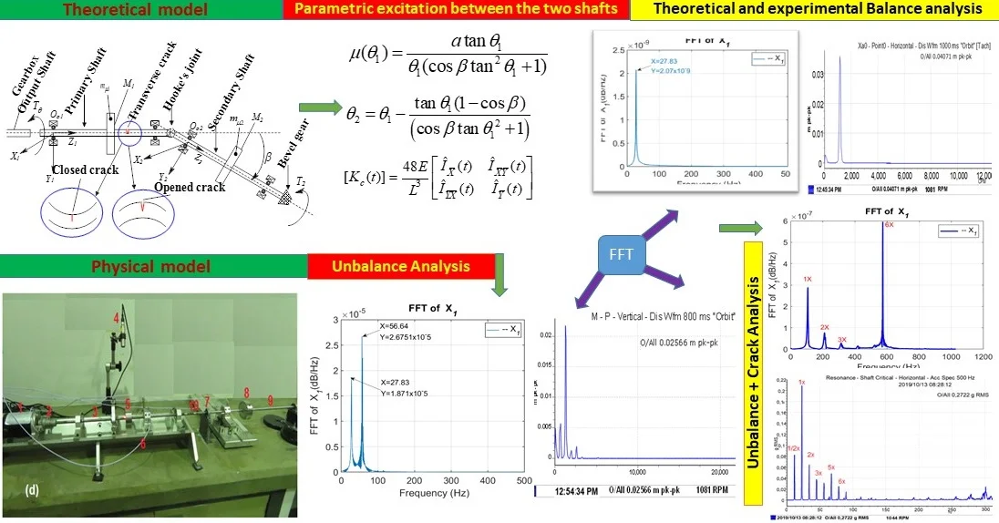
Abstract
This paper presents a theoretical and experimental analysis of a coupled lateral and torsional vibrations of two identical rotors interconnected by a flexible Hooke’s joint and modelled as a multibody system with a small misalignment angle. Using energy principle and a Lagrangian transformation, the governing equation of the propeller shaft system is established by considering a nonlinear elastic shaft time-dependent perturbation. To study the sensitivity of the crack for a rotating shaft, the model is enriched by considering the periodical feature of the time-varying stiffness deriving from the crack breathing model. The nonstationary response of a cracked rotor system in the presence of unbalance has been evaluated using orbit patterns and Fast Fourier Transform. The highly oscillated feature of the rotors system is theoretically obtained and experimentally analysed. The analysis demonstrated that the crack parameters in the input shaft tend to inhibit the occurrence of unstable oscillations in lateral deflection, orbit and frequency spectrum of the secondary response. It is also found that the passage of the cracked primary shaft near to an integral multiple of the critical speed leads to the phenomenon of sup-harmonic resonance. Subsequently, the experimental analysis conducted equally indicated that the quantitative relation between the faults and the performance of the transmission is impacted by the time-varying stiffness and is the main cause of the frequency-modulated feature in the Cardan shaft system. Finally, the experimental results were informative for the transient response exploration and comparable to the theoretical findings for validating the proposed twin-rotor model.
Highlights
- Numerical and experimental analysis of faulted twin-rotor interconnect through Hooke’s joint
- Expression of a perturbation unction and parametric crack excitation in the input shaft
- Theoretical and experimental FFT exhibited a higher frequency amplitude of the system on both shafts
- FFT reflected the synchronous excitation frequencies but is not enough to detect the non-linearity effects
- Hooke’s joint effect dominates the vibration signal and cracks effects are masked, which can confuse the analysis
- Experimental results were informative and comparable to the theoretical findings for validating the proposed twin-rotor model
1. Introduction
The universal joint system, as one of the critical components of mechanical components, is often used in rotating mechanical equipment, such as the automobile industry. The universal joint or Hooke’s joint is used for the power transmission when the input shaft is misaligned with the output shaft; it is one of the main components of the transmission system. The performance of the universal transmission system can be often impacted by the presence of faults and needs to be considered during the design process. After unbalance, coupling misalignment is the most common fault present in rotating machines [1]. Various research has been conducted to study the dynamic stability of the shaft interconnected through a joint. However, In the case of the rotating shafts interconnected with joint parametric instability in a rotating shaft system may be a result of the asymmetric shaft, anisotropic bearing, cracked shaft, the applied a periodic variation of velocity ratio and the angular misalignment [2]. The steady-state response, resonance and dynamic instability were investigated in a rotating Timoshenko shaft with rigid unsymmetrical disc subjected to a periodic axial force as a parametrically excited system using Finite Element Method [3]. It was found that the dynamic instability of the system and the fluctuating part of the axial force has caused the regions of the dynamic instability with increasing amplitude of the fluctuation. It was reported early in [4] that the existence of this instability can cause noticeable noise, severe mechanical shakes and premature fatigue failures in shafts, gear teeth etc. Sekhar and Prabhu [5] investigated the effects of flexible-coupling misalignment on the vibrations of a rotor-bearing system. A linear system was analysed and a solution obtained by assuming the resulting vibration response to comprise of 1× and 2× components. Using this approach, it was demonstrated that the location of the coupling, with respect to the bending mode shape, has a strong influence on the vibrations.
Furthermore, a similar problem was investigated under linear and non-linear conditions [6]. Results showed that parametric instabilities that occurred depended on the input shaft speeds and the Hooke’s joint angle. The existence of parametric resonance, quasi-periodic and chaotic motions were shown under the non-linear governing equation. A model for analysing partial vibration of a two-shaft cracked propeller system coupled with a Hooke’s joint has been discussed in [7].
The model was derived from the equations of vehicle dynamics and vibration theory. The resultant governing system of equation was numerically solved and explored by nonstationary signal processing based on Wavelet Transform techniques. A few recent studies with major assumptions were made in respect to rotor motions and have shown some promise, in respect of the rotor motions to ensure that the results would be correlated with expected form [8-10]. It is clear from the literature that the relationship between shaft coupling and machinery vibration is still not fully understood. The fundamentals of a realistic model interconnected shafts through joint might be best followed by recoursing to a few complex mathematical models comprising the rotordynamic elements present in real rotor systems. Based on this conception, the present study aims to explore the influence of faults on the performance of the universal transmission joint and its effects by enhancing the previous research presented in [9, 10] for an unbalanced and cracked twin-rotor system. The analysis is performed theoretically and experimentally on a complex nonlinear rotordynamic model subjected to Hooke’s joint coupling effects to investigate the resulting system motions and transmission performance. This work is, therefore structured as follows. Section 1 briefly summarised the research work done so far on different modelling techniques, the system behaviour and fault. Section 2 introduces the coupled twin-rotors model and develop the perturbation parameter during torque transmission using a Hooke’s joint. The model is enriched by considering, the effect of the crack on the input shaft and the transmission of the movement to the second shaft under the impact of the speed and crack in Section 3. The governed equation of the system is established in Section 4. The simulation of the proposed model on the transmission performance for the faults such as unbalance associated with the Hooke’s joint, and breathing crack are analysed in Section 5. The model is validated experimentally on a modified rotor-kit 4 Bently Nevada laboratory rotordynamic system in Section 6, following at the end by the conclusions in Section 7.
2. Mathematical model of the study
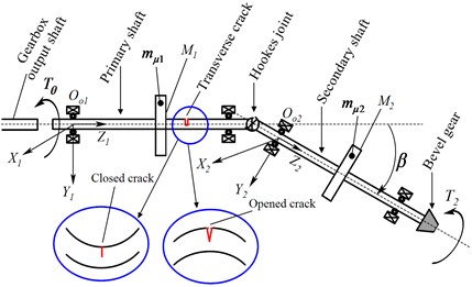
The modelling of the twin-rotor systems will presume the adoption of an “elastic body” that can involve rotation as well as deflection; thus, the dynamic properties are more complex. This section is devoted deriving a basic mathematical model of coupled twin-rotor which can be used to study the vibration response of unbalanced and cracked rotor systems. The model is based on a simple Jeffcott’s approach aiming at an intuitive and straightforward interpretation of the system excitation-response relationships. Fig. 1(a) represents the modelled twin-rotor system. Its essential elements are the primary and secondary shafts, bearings, and a Hooke’s coupling. The twin-rotor system considered comprises two symmetric elastic shafts each carrying a massive rigid disc; which are characterised by the system’s kinetic energy. The two discs are of masses and . and carry eccentric unbalanced lumps of masses, and respectively.
The following assumptions and considerations have been made: 1) The two shafts are flexible to assure lateral and torsional vibration. 2) The gyroscopic effects due to discs’ spinning are neglected. 3) The shafts flexural stiffness are considered to be relatively small compared to the bearings’ stiffness. 4) The linear viscous damping effects of the bearings has been considered. 5) Gyroscopic effects due to the spinning disks are negligible. 6) Self-aligning bearings are assumed, to ensure that the bearing takes up the bending mode shape of the shafts at the supports. 7) The power spends to overcome the torsional vibration is nil, and the damping force is independent of the reactions at the Hooke’s joint. This assumption provides for the inclusion of the Rayleigh dissipation function in the Lagrangian equation. Therefore, The system’s d.o.f.s are lumped at the centres of the inertias and their net displacements are as follows: the motor mass moment of inertia that undergoes elastic-body rotation of the gearbox output inertia only. – the Net mass moment of inertia of the mass-disc transmitted through the Hooke’s joint that undergoes elastic-body rotation , and the angle of intersection of the primary and secondary shaft axes . Hooke’s couplings have been modelled by applying the kinematics associated with universal-joints. The shafts are only loaded in lateral and torsional deflection, transversally balanced, and the magnitude of sufficient lateral stiffness is far more significant than torsional stiffness. Finally, the transfer of vibration from the motor gearbox to the input shaft is negligibly small in comparison to the torsional vibration of the input shaft system.
Fig. 1a) Sketch of a cracked Cardan shaft, b) assembly in a deformed configuration
a)
b)
Fig. 2a) Deformed configuration of shaft1and disc 1, b) deformed configuration of shaft 2 and disc 2
a)

b)
2.1. Perturbation function between shaft input and output
It is well known that in automotive assembly, the difference between input and output motions of a Cardan shaft is kept low to reduce vibration in the coupling [11]. This is achieved by curbing to a low value, usually below 6°. Let the net displacement of being expressed as:
where, is a small perturbation parameter that depends on . The kinematic relationship between the output is given by:
where is the angle of inclination of the secondary shaft. Combining Eqs. (1) and (2), yields:
and allowing for infinitesimal small-angle approximation on leads to:
For a limited range of , Eq. (4) will be finite and periodically convergent. Making the subject in Eq. (4) gives:
The difference between and the output for infinitesimal small-angle approximation gives:
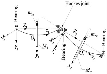
2.2. Mathematical model of the proposed twin-rotor system based on Lagrange methods
The combined inertial reference frames, , , and , , as shown in Fig. 2(a)-2(b) have been adopted for the global representation of the lumped mass system. , , is fixed to the gearbox with coincident with the gearbox output shaft axis. Whereas, , , is attached to the left bearing of the secondary shaft such that, is coincident with the central axis of the bearing as indicated in Fig. 1(a). The vectors and represent the global position of and respectively. The pairs of vectors , and , respectively, represent the centres of the rotor masses and .
2.3. Formulation of the kinetic energy of the rotor system
Combined lateral and rotational displacements of the system, the system kinetic energy comprises the kinetic energy of the components of the primary shaft 1 () and the secondary shaft 2 (), and expressed as:
which yields to the kinetic energy expressed as:
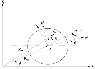
Here and are the velocity vectors of unbalance masses and respectively and rotating with the moment of inertia of disc 1 and disc 2. The vectors and can be expressed as [12]:
The matrices rotational transformation, and are defined as:
The matrices have the following significance: – rotational transformation from the motor-gearbox coordinate system , to the inertial reference frame , . – the rotational transformation from the left secondary disc coordinate system , to the reference frame , .
Differentiating and with respect to time gives:
where, , and , and represent locations of and in their respective disc’s body coordinate systems , and , as indicated in Fig. 2(a) and 2(b). The pairs , and , are components of and in , and , coordinate.
Differentiating Eq. (7), assigning and performing appropriate substitutions of Eqs. (8a) to (10b) leads to the kinetic energy Eq. (11) below:
2.4. Formulation of the potential energy of the rotor system
The system potential energy comprises the shaft lateral vibration strain energy and the torsional strain energy expressed as:
where, , , , , are the shaft stiffness, and are the torsional stiffness coefficients associated with the system degrees of freedom.
2.5. Formulation of the Rayleigh dissipation function expression
Taken into account the effect of damping coefficient, and neglecting the exciting external force and the external torque, the Rayleigh’s dissipation function can be expressed as:
where, , , , are the flexural vibration damping of the respective degree of freedom’s damping coefficients, and are the torsional vibration damping of the first and second shaft, respectively.
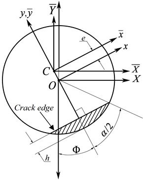
3. Mechanism and introduction of the breathing crack function
Considering that the input shaft 1 has a radius with a transverse crack, as shown in Fig. 3, the centroidal area moments of inertia of the cracked element about the and axes are and , respectively.
Fig. 3Breathing crack cross-section: after the shaft rotates. The dashed area represents the crack segment
In [13], the time-varying area moments of inertia , and about the centroidal and axes during the shaft rotation are given in terms of centroidal area moments of inertias and in the rotating and axes as [14] product of inertia (cross-moment of inertia) are given as:
where , , and are the area moments of inertia of the cracked element cross-section about the rotating and axes, is the area of the cracked element cross-section and is its centroid location on the -axis. Since is the axis of symmetry of the cracked element cross-sectional area during rotation, then . The quantities and have been derived in [14] as:
The area moments of inertia and of the cracked element cross-section about the rotating - and -axes, or the fixed and axes, have also been derived for as:
where and is the non-dimensional crack depth and is the crack depth in the radial direction of the shaft. The detailed calculation process can be found in [13, 14]. Therefore, the instantaneous area moment of inertia values about the principal centroidal directions, and , is calculated as:
The functions and in Eq. (14) representing the opening and closing effect can be expressed in the Fourier series as:
where defines the rotational speed of the rotor. The complete stiffness matrix of the vertical cracked rotor in the fixed coordinates is obtained via the transformation matrix of dimension 2×2 as:
where is the modulus of elasticity, is the length of the rotor. Due to the axis of symmetry of the cracked element cross-sectional area during rotation yield .
4. The governing equations of motion
Lagrangian equation of a system in each generalised coordinate frame is:
Upon substitution of Eqs. (11)-(13) and (22) into Eq. (23), performing requisite differentiation and manipulation, the system dynamic equation reads:
The elements of mass, stiffness and damping matrices in their final forms are:
The vectors , have been analytically obtained by the Lagrangian formalism and are the vector of Carioles couple corresponding to the rotor quadratic velocity excited torque and the elastic interaction of rotor’s stiffness of the secondary shaft in terms of the perturbation of primary shaft assembly through the Hooke‘s joint. Based on Eq. (24), the dynamic responses and transient stiffness of the rotor system can be obtained by the Runge-Kutta Fehlberg method. The derived system equation is numerically solved and experimentally explored next.
5. Results and analysis
The numerical solutions of Eq. (24) of the twin-Cardan shafts are evaluated using the values of parameters prescribed in [10]. A numerical simulation was conducted at a variable rotating speed, and under the condition without crack, namely only balance effect is considered, as shown in Fig. 4 in the lateral direction.
In the first simulation, the rotor system was operated with zero eccentric mass and was therefore considered balanced and is the baseline reference before introducing faults to the system. This is to ensure that the fluctuations in the vibration spectra are purely due to the induced defects. Fig. 4, illustrates the response of the stable rotor system. The present frequency domain features indicating more quickly the critical shaft speed where a natural frequency and excitation frequency coincide at approximatively 27.83 Hz which for both shafts are sufficient for vibration analysis of balanced rotating machine. The orbits of the shaft 2 due to the joint angle cease to be an elliptic shape with a predominance of eccentric loops, as indicated in Fig. 4(b).
Fig. 4Dynamic response of the balanced rotors-system passing near to the critical speed as a function of the speed
a) The orbit of the balanced shaft 1 (Stable operation)
b) The orbit of the balanced shaft 2 (Stable operation)
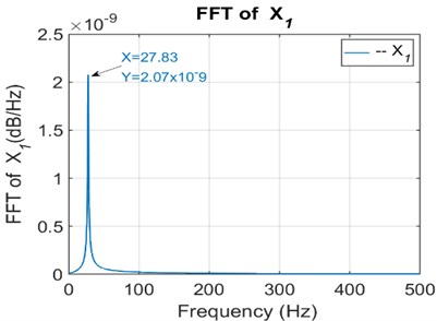
c) FFT of the secondary shaft1
d) FFT of the primary shaft 2
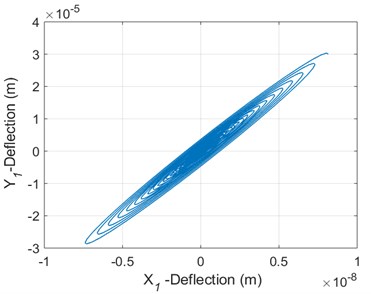
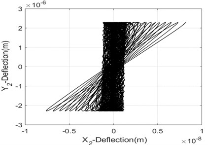
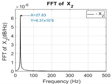
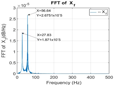
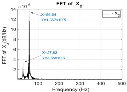
To conduct an unbalance fault analysis, an additional mass of pre-determined weight was introduced into the system and resulted through orbit and FFT are presented, as shown in Fig. 5. The obtained results show that vibration due to combined misalignment and unbalance is characterised by two times running speed frequency component at high-level harmonics. Moreover, apart from the basic harmonic of 27.83 Hz, a second harmonic frequency spectrum of 56.64 Hz, as shown in Figs. 5(c) and (d) exists. Simultaneously, the difference between the orbits is quite significant. These parametric instabilities that occurred on the frequency depended merely on the Hooke’s joint angle and the input shaft speeds. The shafts 1 and 2 have distorted elliptic-shaped movements with several disturbing loops on the second shaft. The shafts orbits displayed in Figs. 5(a) and (b) are more complex and are not a standard circle any more.
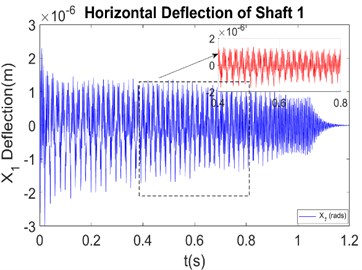
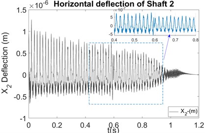
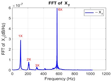
The numerical simulation of an unbalance vibration system with a transverse crack was carried out at the same speed, and the dynamic responses were displays using the displacement shaft centre and the frequency spectrum of the response. When a crack occurs in a primary shaft system, vibration responses in -direction and -direction of shaft 1 and 2 respectively are distorted harmonically with the appearance of multiple tighten peaks as seen in zoomed Figs. 6(a)-6(b). The FFT analysis in an interconnected twin-rotor through Hooke’s joint yielded satisfactory results when performing online crack fault identification. As in the previous case, only the first harmonics have significant effects on the system response, (see Figs. 4(c) and 4(d)). At critical speed, the 1× of the input shaft decrease significantly due to the crack effect while the second shaft critical speed increase as the shaft passes through the natural frequency. Examination of the frequency spectrum of shaft 1 and 2, cf. Figs. 6(c) and 6(d), shows the presence of multiple harmonics of the critical velocity (2 ×, 3 ×, 4 × ...) for the crack system. It is noted as seen for the unbalanced system, a transfer of crack features through the connecting joint by the presence of the high super-harmonic frequencies 1 ×, 2 ×, 3 × ... which reflects the action of breathing of the crack on the dynamic behaviour of the input shaft. The frequency range and magnitude of decrease where the 1× rpm is influenced is dependent upon the transient stiffness of the flexible rotor. In this simulation, there is a critical speed at approximately 100 Hz. Thus, during the operation of a rotating machine, the observation of super-harmonic resonances passing through integer multiples of the critical speed and the change of the harmonic shape of the deflection of the shaft can be a good indicator of the existence of cracks.
Fig. 5Dynamic response of unbalanced rotors-system passing near the critical speed as a function of the speed of rotation
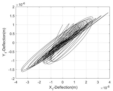
a) The orbit of unbalanced shaft1 (Unstable operation)
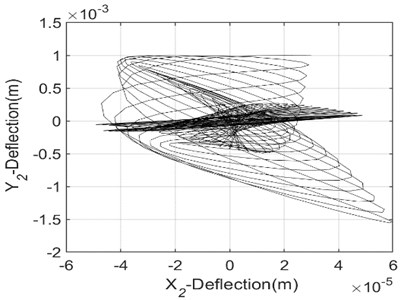
b) The orbit of the unbalanced shaft 2 (Unstable operation)
c) FFT of the unbalanced shaft 1
d) FFT of the unbalanced shaft 2
Fig. 6Dynamic response of the unbalanced and cracked rotors-system passing close to the critical speed Δk/k0= 0.45
a) Time evolution of the cracked shaft 1
b) Time evolution of the cracked shaft 2
c) FFT of the cracked shaft 1
d) FFT of the cracked shaft 2
6. Experimental correlation to the theoretical results
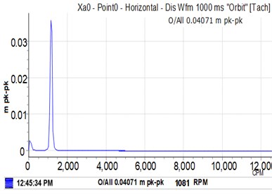
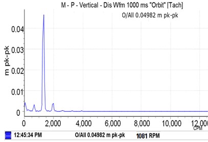
The test bench set up for the study of the power transmission between two shafts through the Hooke's joint aims at the measurement of the natural frequencies and the determination of parameters making it possible to establish a comparative analysis with the adopted numerical approach. Here, the theoretical observations are experimentally verified using a modified rotordynamic simulator Rotor-Kit 4 of Bently Nevada shown in Fig. 7, which physical parameters were previously used in [12]. The length of both shafts is 640 mm and its diameter is 10 mm. The rotor system is driven by an electric motor coupled to the input shaft through a flexible coupling. The practical interconnected rotor is shown in Fig. 7(a). The experimental device consists of a frame, a drive system, and the rotors which comprise each of a lumped mass disc. The driven shaft is supported by two self-aligning bearings; the assembly is mounted on a concrete base and isolated from the environment by layers of elastomeric material which also serve as vibration absorbers. The vertical and horizontal vibration amplitudes data have been collected through four perpendicular proximity probes installed on the left side of both shafts, as shown in Fig. 7(d). The readings of the proximity sensors in Fig. 7(c) were collected at a sampling frequency of 500 Hz by the Bently Nevada data acquisition system recorder. To get the baseline result, the experiments were first performed using both balanced discs with at a maximum Hooke’s joint angle of 60. For this experimental investigation, the cracked input shaft I has been considered as a value of a non-dimensional crack depth = 0.45 is located at midspan of the shaft. Experimental studies through a series of tests were therefore performed, the amplitudes of the intact shaft, the unbalanced shaft-I and Shaft-II, and the cracked shaft-I are plotted in Fig. 8.
The first conducted test has permitted the system assessment for a case where no unbalance forces are acting on the rotors system. Fig. 8, shows the frequency spectrogram of the rotor axis’ orbit of the lateral vibrations of the balanced rotors passing through its first critical speed in time domain under stable conditions at variable speeds. Further, the presence of an eccentric mass on a disc, generate a greater eccentric force of both flexible shafts, it will be therefore interesting to analyse the influence of the bending through the misaligned shafts.
Fig. 7Experimental setup is composed of a) a cardan shaft, b) unbalanced mass location set at 0°, c) data acquisition control, d) modified rotor kit- 4 components (1): motor, (2): flexible coupling, (3): input shaft 1 (4): tachometer (5): disc1, (6): probes, (7): self- aligning bearing, (8): disc 2, (9): output shaft 2, (10): hooke’s
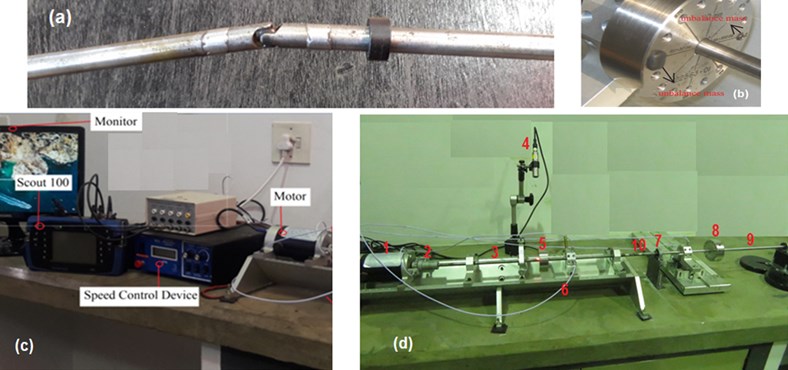
Fig. 8Experimental baseline response of the balanced rotors-system passing near to the critical speed
a) The orbit of the balanced shaft 1 (Stable operation)
b) The orbit of the balanced shaft 2 (Stable operation)
c) FFT of the secondary shaft1
d) FFT of the primary shaft 2
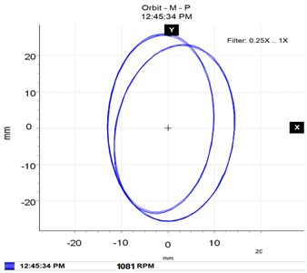
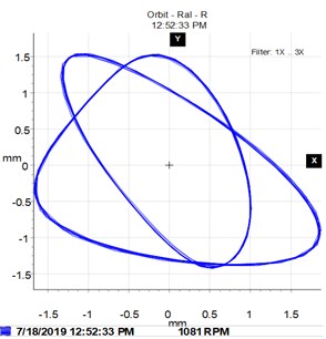
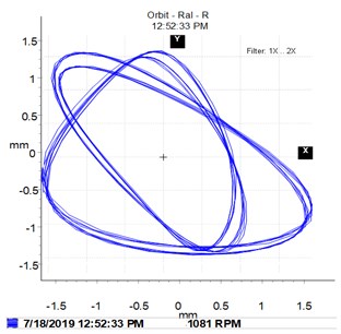
The previous experiment is then repeated at the same motor speeds, and the features of the rotors system are then extracted. The initial balanced rotors discs were then unbalanced by two identical mass of 0.4 g set in the hole at 0° within the crack side to generate an unbalance moment of 4 g.mm as shown in Fig. 7(b). The first conducted test has permitted the system assessment for a case where no unbalance forces are acting on the rotors system. Fig. 8 shows the frequency spectrum of the rotor where, at critical speeds of 1 × rpm, the frequency increase significantly and then decrease as the shaft passes through the natural frequency. The orbit of the lateral vibrations of the balanced rotors passing through its first critical speed is in stable conditions. Observation of the orbit of Figs. 8(a) and 8(b) show simple circular shapes from the evolution of the input shaft to output shaft.
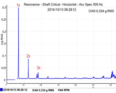
The complexity of the non-linear response is reflected by non-negligible contributions of the orders ×, which are characterised by an orbital movement in vary form: circular, leaning, or plane orbits. It is therefore clear that the non-linear dynamic response for the entire system can be very complex over the entire operating range of the system. Thus, during this experiment, the orbits are given for specific rotational speeds, characteristic of the rotor at the critical speed. At the passage of critical speeds, the orbits of the rotor find classic circular or elliptical forms with a predominance of the order 1 × over the global response, observable at around 1030 rpm. This phenomenon of the presence of the 1/2 × orders (Figs. 9(c) and 9(d)) results in the formation of external and/or internal loops, as shown in the Figs. 9(a) and 9(b). It is shown clearly that the sub-harmonic peaks amplitude levels depend greatly on the unbalance excitation when the input shaft is accelerated. From these results faults on both connected shafts, unbalance is considered as the most commonly observed disturbance source in twin-rotor systems.
Fig. 9Experimental response for the unbalanced fault conditions near the critical speed
a) The orbit of unbalanced shaft1 (Unstable operation)
b) The orbit of the unbalanced shaft 2 (Unstable operation)
c) FFT of the unbalanced shaft 1
d) FFT of the unbalanced shaft 2
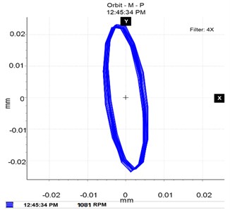
Fig. 10Experimental response for the unbalanced and crack fault conditions near the critical speed Δk/k0= 0.45
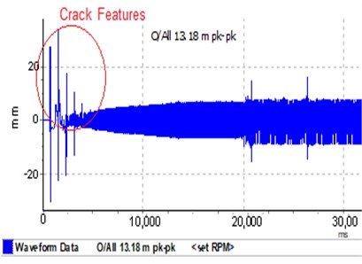
a) Time evolution of the cracked shaft 1
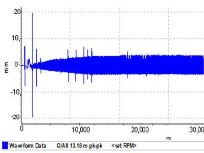
b) Time evolution of the cracked shaft 2
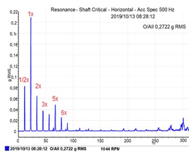
c) FFT of the cracked shaft 1
d) FFT of the cracked shaft 2
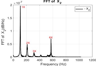
Interest is now focused on the combined contributions of unbalance and crack, their influence on the nonlinear dynamic response in the presence of nonlinear forces. The experiments show that the system motion generally contains the multiple harmonic components, and under some special conditions, the 1/2 × fractional harmonic components of unbalance effect were observed (Fig. 10(c)). Based on these researches, it is not so difficult to judge whether a rotor system has a crack or not. Previous studies such as [5, 15, 16] have shown that for a rotor passing through its critical speed, a sub-resonance that is smaller in amplitude than the fundamental resonance and buried in noise of the transient response can be a good indicator of crack presence. The present study confirms these statement by showing the presence of multiple sub-harmonics peaks buried in noise as shown in Figs. 10(a) and 10(b) as the rotor passed the critical speed. For this, the evolution of the lateral displacement of the cracked tree is discontinuous.
Moreover, the features of crack can be observed in the frequency spectrum by the appearance of sup-harmonic peaks (2 ×, 3 ×, 4 ×…) as shown in Figs. 10(c) and 10(d). Crack features are hugely dominant and mask the unbalance excitation features which cannot be easily discernible in the transient response of the output shaft. The significant experimental observation is related to the Hooke’s joint impact, the higher excitation of the shaft 1 is partially transmitted to the second shaft through the Hooke’s joint. To identify the effect of interaction between crack and other faults present in the input shaft I, exploration of distinct features of fault in the output shaft II sub-critical transient response, can permit to visualise at low amplitude the symptoms of input shaft fault.
From these results, it can be deduced that the presence of several sup-harmonics in the transient response with a noisy background and the multiple gradually decreasing amplitudes peaks at the starting motion is considered the distinct crack features. Meanwhile, it can be observed in the vibration transmission that the background noise and relatively equal fault feature amplitudes in shaft II are due to the distinct shaft misalignment angle. These results are in good agreement with the numerical results. However, when crack and unbalance, and misalignment co-exist, features extraction and monitoring of crack fault become more difficult. The Hooke’s joint effect dominates the vibration signal and, hence, the crack effects are masked, which can confuse the analysis. Therefore, there is a need to use sophisticated and appropriate signal processing techniques to extract and distinguish the crack feature from each other faults.
7. Conclusions
The main objective of the present study was to model and analyse the vibratory responses of a twin-rotor system to distinguish the transmission of fault such as crack and unbalance through a Hooke’s joint. To simulate and extract the characteristic features of the studied faults, the governing equation of the transient lateral and torsional vibration of the twin-rotor system is established based on energy principle. A parametric excitation simulating a breathing crack, unbalance and shaft misalignment are introduced into the model and yields a highly nonlinear system governing equation. The study has allowed exploring theoretically, the non-linear dynamic behaviour of the system due to the crack from the shaft I to the shaft II. This was as well done experimentally on a modified Rotor Kit-4 by considering the geometry parameters and constraints of the Hooke’s joint. The study made it possible to conclude that the passage of the rotor with rotational speeds close to an integral multiple of the critical speed leads to the phenomenon of sup-harmonic resonance. This phenomenon, as noted, results in a high vibratory level reached by the excited harmonic (harmonic of order 1×) and an orbit formed of several loops intertwined and disordered. Subsequently, some qualitative analysis conducted experimentally indicated that the time-varying stiffness induced by breathing crack is the main cause of the frequency-modulated feature of the connected twin-rotor system. The transmission through Hooke’s joint is also influenced by the faults, as the transfer motion from the input shaft to the output is impacted by the damage features. In practical for twin-rotor that operate in the super-critical range, the presented fault features can be used as useful indicators when unbalance and crack faults are suspected rotors system. Finally, the experimental results were informative for the transient response exploration and comparable to the theoretical findings for validating the proposed twin-rotor model.
References
-
Sudhakar G. N. D. S., Sekhar A. S. Coupling misalignment in rotating machines: modelling, effects and monitoring. Noise and Vibration Worldwide, Vol. 40, Issue 1, 2009, p. 17-39.
-
Wahab A. M., Rasid Mohd Rudin Z. A. N. F., Abu A. Dynamic stability of shaft interconnected through joint: a review. ARPN Journal of Engineering and Applied Sciences, Vol. 10, Issues 15, 2015, p. 6310-6318.
-
Pei Y.-C., Lu H., Chatwin C. Dynamics of a rotating shaft-disc under a periodic axial force. Proceedings of the Institution of Mechanical Engineers, Part K: Journal of Multi-body Dynamics, Vol. 224, Issue 2, 2010, p. 211-219.
-
Bulut G. Dynamic stability analysis of torsional vibrations of a shaft system connected by a Hooke’s joint through a continuous system model. Journal of Sound and Vibration, Vol. 333, Issue 16, 2014, p. 3691-3701.
-
Sekhar A. S. A., Prabhu B. S. Effects of coupling misalignment on vibrations of rotating machinery. Journal of Sound and Vibration, Vol. 185, Issue 4, 1995, p. 655-671.
-
Asokanthan S. F., Meehan P. A. Non-linear vibration of a torsional system driven by a Hooke’s joint. Journal of Sound and Vibration, Vol. 233, Issue 2, 2000, p. 297-310.
-
Alugongo A. A. Parametric excitation and wavelet transform analysis of a ground vehicle propeller shaft. Journal of Vibration and Control, Vol. 20, Issue 2, 2014, p. 280-289.
-
Alugongo A. A. Parametric vibration of a cardan shaft and sensitivity analysis. Proceedings of the World Congress on Engineering and Computer Science, 2018.
-
Tchomeni B. X., Alugongo A. A., Masu L. Modeling and vibration analysis of twin-rotor system interconnected by a Hooke’s joint (Part A). Vibroengineering Procedia, Vol. 27, 2019, p. 1-6.
-
Tchomeni B. X., Alugongo A. A., Masu L. Experimental setup for unbalance fault detection and vibration analysis in a Cardan shaft (Part B). Vibroengineering Procedia, Vol. 27, 2019, p. 97-102.
-
Reza N. Vehicle Dynamics: Theory and Application. Springer Science, 2008.
-
Tchomeni B. X., Alugongo A. A., Masu L. M. In situ modelling of lateral-torsional vibration of a rotor-stator with multiple parametric excitations. International Journal of Mechanical, Aerospace, Industrial and Mechatronics Engineering, Vol. 8, Issue 11, 2014, p. 15695.
-
Al Shudeifat M.-A., Butcher E. A., Stern C. R. General harmonic balance solution of a cracked rotor-bearing-disk system for harmonic and subharmonic analysis: analytical and experimental approach. International Journal of Engineering Science, Vol. 48, Issue 10, 2010, p. 921-935.
-
Al Shudeifat M.-A., Butcher E. A. New breathing functions for the transverse breathing crack of the cracked rotor system: approach for critical and subcritical harmonic analysis. Journal of Sound and Vibration, Vol. 330, Issue 3, 2011, p. 526-544.
-
Sawicki J. T., Wu X., Baaklini G. Y., Gyekenyesi A. L. Vibration-based crack diagnosis in rotating shafts during acceleration through resonance. Nondestructive Evaluation and Health Monitoring of Aerospace Materials and Composites II, Vol. 5046, 2003, https://doi.org/10.1117/12.484297.
-
Sinou J.-J. An experimental investigation of condition monitoring for notched rotors through transient signals and wavelet transform. Experimental mechanics, Vol. 49, Issue 5, 2009, p. 683-695.
Cited by
About this article

The authors acknowledge the help of the Vaal University of Technology and would like to acknowledge and appreciate as well the support of the Council for Scientific and Industrial Research (CSIR) South-Africa.
