Abstract
The tuned mass damper (TMD) is an effective way to deal with excessive vibration of structures. Its high efficiency is, however, conditioned by proper design. The optimization of TMD is a complicated process, because a closed-form solution for its optimal parameters is known only for several simplified cases. This paper presents an approach of dynamic response calculation of structures with TMD in modal coordinates, which is suitable for repeated evaluations of response to harmonic load which is necessary in case of optimizing TMD parameters for large and damped systems.
1. Introduction
The fast development of new materials and design procedures leads to the design of effective but slender structures. However, structures such as high buildings, towers, and bridges inevitably become susceptible to vibration due to dynamic load. TMD is a very effective vibration control strategy. Many researches have been conducted to propose different optimization criteria and procedures of TMD design. First recommendations of “nearly optimal” TMD tuning and damping for undamped main structure have been introduced by J. P. Den Hartog [1] and J. E. Brock [2] and they are still widely used, especially because of their easy application. The closed-form solution for damped single degree of freedom (SDOF) main system was derived in [3]. A complicated analytical solution for H2 optimization was introduced by O. F. Tigli [4].
However, the SDOF main system model is often insufficient for proper TMD design. Undamped main system of multi-degrees of freedom (MDOF) with attached TMD was examined in [5]. Unfortunately, the proposed design method requires inversion of receptance matrix of the system and numerical solution of nonlinear system of equations. B Islam. and R. Ahsan presented utilization of evolutionary algorithms in TMD optimization [6].
The numerical optimization of tuned mass dampers on damped MDOF structures is the only way to design optimal TMD in many cases. The evaluation of frequency response function (FRF) for large systems has high computational complexity. This paper presents a new approach to the evaluation of response of the structures with single TMD using modal (also called normal) coordinates, which can significantly reduce the computational complexity. Standard mode superposition analysis is not possible, because the viscous damper of TMD has a specific effect on damping matrix and the equations are no longer uncoupled after the transformation of coordinates to the modal ones. The goal of this paper is to show that response of the main structure and the effect of TMD on it can be evaluated separately in modal coordinates. That can be used for either evaluation of efficiency of TMD design or assembly of FRF.
2. The equations of motion
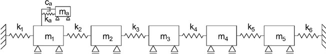
The main system can be either undamped or proportionally damped MDOF vibrational system of degrees of freedom. The tuned mass damper is attached to the th degree of freedom and consists of a mass, spring, and viscous damper. The equation of motion of the main system for general dynamic load is given by Eq. (1):
where , , and are stiffness matrix, damping matrix, and mass matrix, respectively and is the loading vector. represents the vector of displacement, and are the vectors of velocity and acceleration, respectively. It can be shown that TMD with one degree of freedom adds one equation to the system. The complete equation of motion of the entire system can be written as follows [5]:
where , and , are the stiffness, damping, and mass of TMD, respectively. represents the displacement of TMD, and are its velocity and acceleration. The matrices and contain only one non-zero element on the position (×). The values of those elements are and for matrices and , respectively. The symbol expresses th column of and similarly is the th column of :
Assuming is a harmonic force with circular frequency and amplitude , Eqs. (2), (3) can be transformed to Eqs. (6), (7):
3. Response in modal coordinates
The modal coordinates express the vector as a linear combination of the mode shapes. This relation is described by Eq. (8) where is a vector of modal coordinates. The mass-orthonormal mode shapes are used in this paper and they can be arranged as columns of the modal matrix :
The mass-orthonormal modal matrix has several important properties expressed by Eqs. (9), (11) [7]:
where , , and are identity matrix, spectral matrix and modal damping matrix respectively.
Substituting Eq. (8) to Eqs. (6), (7) and left multiplying the first one by , the following result is obtained:
Displacement of TMD can be expressed from Eq. (13) and substituted into Eq. (12). After rearranging and simplifying the result using Eqs. (9)-(11), the modified equation of motion is obtained:
where is the th row of . To obtain the vector of modal coordinates , a system of equations needs to be solved because and are full matrices in general case. However, matrix is diagonal for any type of classical damping and its diagonal members are where is damping ratio of th mode shape and is th natural frequency. Let us assume is such type of matrix. Sherman-Morrison formula expressed by Eq. (15) can be used for finding the inversion of the matrix on the left-hand side of Eq. (14):
Modal coordinates can be found using Eq. (16):
where the following substitutions are used:
It is clearly visible that using classical damping matrix leads to diagonal matrix , which is important because of the need of finding its inversion. Eq. (16) is simplified, rearranged and the th row, which expresses the contribution of th mode shape to total response, is as follows:
In order to solve Eq. (20), two following sums and are evaluated according to the following equations:
These two sums are independent of TMD parameters, therefore their values can be found and used repeatedly while optimizing TMD, which can save computational time. It is important to note that taking the exact contribution of one mode shape requires usage of all mode shapes of the main system to evaluate and . Nevertheless, the contribution of mode shapes with frequencies that are far from pacing frequency is minimal and can be neglected. This is clearly visible from the form of denominators of and . Therefore, using only several relevant mode shapes for evaluation of and leads to very accurate results.
The value of the modal coordinate is composed of two separate members as can be seen in Eq. (20). The first one represents the response of the main system and the second one denotes the effect of TMD.
4. Numerical example
The analysis of the proportionally damped system with 5 DOF was performed to show the effect of TMD and to compare the exact solution to the solutions with a reduced number of mode shapes. Rayleigh damping was used because of its simple application. The damping ratio of the first mode shape 0.02 was chosen and the damping ratios of the other mode shapes were found assuming 0. Parameters and mode shapes of the system are summarized in Table 1. The results can be seen in Table 2.
Table 1Parameters and modal properties of the system
No. | Mass-orthonormal mode shapes [–] | ||||||||
[Nm-1] | [kg] | [N] | [s-1] | ||||||
1 | 10 | 20 | 0 | 0.409 | 0.078 | 0.118 | 0.169 | –0.031 | 0.020 |
2 | 10 | 20 | 0 | 0.748 | 0.130 | 0.104 | –0.111 | 0.073 | –0.070 |
3 | 10 | 10 | 1 | 1.152 | 0.138 | –0.026 | –0.097 | -0.141 | 0.225 |
4 | 10 | 20 | 0 | 1.478 | 0.123 | –0.142 | 0.045 | -0.046 | –0.102 |
5 | 10 | 10 | 0 | 1.662 | 0.067 | –0.099 | 0.067 | 0.252 | 0.134 |
6 | 10 | – | – | – | – | – | – | – | – |
Table 2Peak response in the resonance zone of the third natural frequency
[s-1] | Maximal amplitude [m] | Relative error [%] | |
5 mode shapes, no TMD | 1.151 | 0.1945 | – |
5 mode shapes with TMD | 1.105 | 0.0788 | – |
2-4 mode shape | 1.142 | 0.0762 | –3.30 |
3 mode shape | 1.098 | 0.0791 | 0.38 |
TMD was designed in order to reduce the dynamic response in the resonance zone of the third natural frequency. To design appropriate (but not optimal) parameters of TMD, the classic Den Hartog’s criteria [1, 8] were utilized, which resulted in parameters 1 kg, 1.254 Nm-1, and 0.324 Nsm-1. TMD was attached to the first mass because the first ordinate of the third mode shape has the highest value. Therefore, it’s the most effective position for TMD.
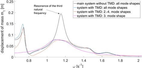
The frequency response functions were found on both the main structure and the main structure with TMD attached. The comparison of these two functions gives us a picture about the efficiency of TMD design. Two other calculations with TMD were performed, which took only the third and 2-4 mode shapes into account while evaluating Eq. (8) and Eqs. (21), (22).
Fig. 1A static scheme of the structure
As can be seen in Fig. 2, the approximate response in the resonance zone provides very accurate results. The response in Fig. 2 is the absolute value of results given by Eq. (8). The aforementioned approach inevitably leads to complex modal coordinates due to both proportional damping of the main structure and the effect of TMD. Therefore, it is important to find the required response according to Eq. (8) in the first place, and then take its absolute value. It also explains that usage of a lesser number of mode shapes can paradoxically lead to positive error values of response which occurred in our case.
Fig. 2Frequency response functions
5. Conclusions
The given approach of dynamic response evaluation may be appropriate choice while optimizing TMD numerically thanks to its low numerical complexity in comparison to standard methods of response calculation. It is important to mention that all the mode shapes and natural frequencies of the main system must be known for taking an exact solution. Nevertheless, the practical application in the previous section demonstrates that consideration of only several mode shapes in Eq. (8) and Eqs. (20), (22) can give highly precise results.
Another advantage of this type of response calculation is that once the mass-orthonormal mode shapes and associated damping ratios and natural frequencies are known, no other information about the structure is required. The evaluation of structures with TMD in modal coordinates also allows for the usage of experimentally obtained mode shapes and natural frequencies of real structures. That may provide an estimation of structural response in case of additional TMD design for existing structure, even if there is no numerical model of the structure.
References
-
Den Hartog J. P. Mechanical Vibrations. McGraw Hill, New York, 1934.
-
Brock J. E. A note on the damped vibration absorber. Journal of Applied Mechanics, Vol. 68, 1946, p. A-284.
-
Nishihara O., Asami T. Closed-form exact solution to H infinity optimization of dynamic vibration absorber: II. Development of an algebraic approach and its application to a standard problem. Proceedings of the SPIE, Vol. 3989, 2000, p. 500-511.
-
Tigli O. F. Optimum vibration absorber (tuned mass damper) design for linear damped systems subjected to random loads. Journal of Sound and Vibration, Vol. 331, Issue 13, 2012, p. 3035-3049.
-
Ozer M. B., Royston T. J. Extending Den Hartog’s vibration absorber technique to multi-degree-of-freedom systems. Journal of Vibration and Acoustics, Vol. 127, Issue 4, 2004, p. 341-350.
-
Islam B. Ahsan R. Optimization of tuned mass damper parameters using evolutionary operation algorithm. 15th World Conference on Earthquake Engineering, 2012.
-
Humar J. L. Dynamics of Structures. Third Edition, Taylor and Francis Group, London, 2012.
-
Krenk S., Høgsberg J. B. Tuned mass dampers on damped structures. 7th European Conference on Structural Dynamics Southampton, University of Southampton, United Kingdom, 2008.
About this article

The authors gratefully acknowledge support from Technology Agency of the Czech Republic (TAČR), project TE01020168 Centre for Effective and Sustainable Transport Infrastructure (CESTI) and CTU SGS19/032/OHK1/1T/11 project Development and Application of Numerical Algorithms for analysis and modelling of structures and materials.
