Abstract
A 3d model of crank connecting rod of a single cylinder internal combustion engine (ICE) is established, whose force analysis was carried out in ADAMS/VIEW using virtual prototyping method. It was found that the results between the analysis and the theoretical calculation results were basically consistent, indicating that the established model is correct and reliable. In order to reduce the inertia force and torque of this ICE, the uniaxial balance method was used to carry out the vibration reduction design based on the balance shaft. The results of virtual experiments showed that the single cylinder internal combustion engine with a balance shaft can greatly reduce the inertia excitation force as well as improve the vibration.
1. Introduction
For single cylinder internal combustion engines, the main source of vibration is the inertia force and torque generated by reciprocating motion of crank connecting rod mechanism. In order to improve the vibration performance of the internal combustion engine, the inertia excitation force should be reduced or balanced, which can be effectively achieved by a vibration reduction method based on balance shaft [1-4].
According to the traditional pattern of product design, physical prototype should be produced for each sample in order to obtain better design scheme. After that, the prototype will be put into the vehicle for testing and be further modified unless meeting the expected requirements.
Such approaches are not only inefficient, but also a serious waste of human and material resources. Thanks to the development of computer technology, virtual prototype technology [5, 6] has gradually replaced the traditional design methods, thus reducing the manufacturing and testing of physical prototype and shortening the period of product development with less cost.
Based on the virtual prototype technology, a virtual prototype model of crank connecting rod mechanism of a single-cylinder four-stroke internal combustion engine was established in ADAMS/VIEW, whose kinematic performance was simulated and verified by theoretical calculations. In order to reduce its vibration, a balance shaft was designed according to the uniaxial balance method. The results of virtual experiment showed that the engine vibration was significantly improved after adding the balance shaft.
2. Kinematics analysis of crank connecting rod mechanism
Single cylinder internal combustion engine adopts the central crank connecting rod mechanism, whose cylinder center passes the rotation center of the crankshaft. Kinematic theoretical analysis on the crankshaft connecting rod mechanism was carried out.
According to the kinematics law of the crank connecting rod, the piston displacement can calculated by Eq. (1) while the first and second order reciprocating inertial force can calculated by Eq. (2) [7]:
In Eq. (1) and (2), is the crank radius, is the length of the connecting rod, is the crank angle, is the swing angle of the connecting rod, is the mass of reciprocating motion including the mass of the piston assembly and the connecting rod end, is the crankshaft rotation angular velocity, is the ratio of the crank radius to the length of the connecting rod.
3. Virtual experimental analysis of crank linkage mechanism
3.1. Establishment of dynamic model of crank linkage mechanism
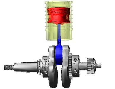
According to the drawings provided by the manufacturer, the 3d model of the single-cylinder four-stroke internal combustion engine is established by UG. From the 3d model, the crank, connecting rod, piston and other components closely related to the vibration of the internal combustion engine are extracted. According to the constraint relation, the dynamic model as shown in Fig. 1 was established in ADAMS/VIEW.
Fig. 1Dynamics model of crank connecting rod mechanism
3.2. Virtual experimental analysis
On the basis of the bench test results, the vibration of the single-cylinder internal combustion engine is quite severe at the speed of 6000 r/min, so the vibration analysis was carried out at this speed. The pressure curve at 6000 r/min was measured by the combustion analyzer.
According to the parameters provided by the manufacturer, the piston displacement curve as well as the ICE’s first and second order reciprocating inertial forces at the speed of 6000 r/min can be determined through Eqs. (1) and (2). Furthermore, the displacement and reciprocating inertia force of the piston can be obtained through virtual experiment in ADAMS/VIEW by applying the cylinder pressure curve to the piston and applying a crankshaft rotation angle changing with time to the crankshaft [8], the reciprocating inertial force is shown in Fig. 2.
From the Fig. 2, it can be seen that the virtual experimental result with a smoother curve is consistent with the theoretical analysis result. This is because the theoretical analysis only considers the first and second order reciprocating inertial forces, while the virtual experimental analysis includes higher order inertial forces. Although different, the displacement curve of piston obtained by virtual experiment and theoretical method is basically consistent as higher order only accounts for a small part. In a word, the dynamic model is accurate and reliable for subsequent vibration reduction design based on the balance shaft.
Fig. 2Reciprocating inertial force at 6000 r/min
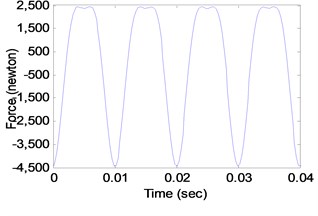
a) Theoretical calculation method
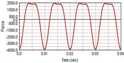
b) Virtual experimental method
4. Vibration reduction design of the balance shaft
The vibration of the single cylinder ICE is serious according to the bench test, mainly influenced by the inertia force and turning moment. In order to address this issue, the inertial force of the ICE must be balanced.
The inertial force of ICE includes rotary inertial force and reciprocating inertial force. As the rotary inertial force has been balanced by the balance mass block set on the crank, the vibration of ICE is mainly caused by reciprocating inertial force, in which the first order reciprocating inertial force plays a decisive role. Therefore, it is necessary to balance and reduce the first order reciprocating inertial force which can be calculated as: .
4.1. Balance method of reciprocating inertia force for ICE
Single cylinder internal combustion engine is compact in structure, and there are three balance methods suitable for reducing its inertia force: excessive balance method, uniaxial balance method and biaxial balance method [9].
(1) Excessive balance method.
Excessive balance method is shown as Fig. 3, excessive balance mass is put at ,which is the extention of crank, to make the component force of the centrifugal force along the piston movement direction is opposite to the direction of the piston reciprocating inertial force, thus being able to balance all or part of the piston reciprocating inertia force according to the mass of counterbalance, however additional force would be produced in the direction [10, 11].
Excessive balance method is suitable for ICE of low displacement while needs to be matched with the frame, which is not good for the fuel economy as well as the development of internal combustion engine.
(2) Uniaxial balance method.
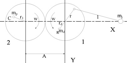
The principle of uniaxial balance is shown in Fig. 4, where is the distance between the balance shaft and the crankshaft, is the mass of the counterbalance, is the mass of reciprocating motion, and is the rotation radius of the counterbalance.
Uniaxial balance method is to design the balance shaft on the basis of excessive balance method. Firstly, half of the first order reciprocating inertial force is balanced by adding the counterbalance at point to satisfy: . At the same time, add a balance shaft whose distance from the crankshaft is A. This balance shaft, together with gear 1 connected to the crank, drives gear 2 on the balance shaft (with equal number of teeth) to rotate in reverse at constant speed. Set the counterbalance at point C to satisfy the following equation: .
The sum of the components force along the axis of the inertial force generated by the two counterbalances is: , which just counteracts the first order of reciprocating inertial force. In addition, the additional force on the axis generated by the two counterbalances just offsets.
(3) Biaxial balance method.
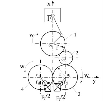
The principle of the biaxial balance method is shown in Fig. 5. With the help of idler 2, gear 1 mounted on the crankshaft drives gear 3, which is engaged with gear 4 mounted on another shaft. Both of them rotates at the angular speed of the crankshaft. Counterbalance is installed on shaft of gear 3 and gear 4. When the crankshaft rotates, the component of the rotary inertia force generated by the balance weight in the direction will be balanced with the first-order reciprocating inertia force of the internal combustion engine, and the additional force in the direction is also balanced.
Fig. 3Excessive balance method
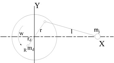
Fig. 4Uniaxial balance method
Although biaxial balance mechanism can completely balance the first-order reciprocating inertia force of the internal combustion engine, it is not suitable for the vibration reduction design due to its complex structure and the need to increase the cylinder diameter, which will increase the cost.
To sum up, uniaxial balance method can not only reduce the first order reciprocating inertial force to a large extent, but also is simple to process in engineering without increasing much volume and weight. Therefore, uniaxial balance method is adopted to carry out the vibration reduction design of the single-cylinder internal combustion engine.
Fig. 5Biaxial balance method
4.2. Design of balance shaft
The reciprocating mass 0.1582 kg and the crank radius 27mm can be determined from the physical object and three-dimensional model of the single-cylinder internal combustion engine. According to formula, the excessive balance can be determined as: 2.136 kg·mm, and the balance quantity of the counterbalance meets: 2.136 kg·mm.
Considering the installation of the balance shaft as well as the volume, mass and other factors of the crankcase, the rotation radius of the balance shaft was determined as 17 mm, thus the mass of the counterbalance is 0.1257 kg. The balance shaft is designed as shown in Fig. 6.
4.3. Establishment of dynamic model with balance shaft
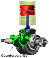
The dynamic model of the crank connecting rod mechanism with balance shaft of the single-cylinder internal combustion engine is established in ADAMS\VIEW, as shown in Fig. 7.
Fig. 6Balance shaft
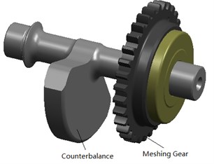
Fig. 7Crank connecting rod with balance shaft
4.4. Vibration reduction analysis of the balance shaft
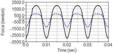
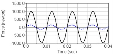
The model is analyzed at the speed of 6000 r/min. The inertial excitation force before and after balancing is compared as shown in Fig. 8.
Fig. 8Internal combustion engine inertia excitation force (6000 r/min)
a) Piston direction
b) Perpendicular to the piston direction
In Fig. 8, the solid line is the internal combustion engine excitation force without the balance shaft, and the dotted line is the internal combustion engine excitation force with the balance shaft added to reduce the vibration. It can be seen that after the balance shaft is added to reduce the vibration, the inertia excitation forces along the piston direction and perpendicular to the piston direction are both greatly reduced. Among them, the root-mean-square value of the inertial force along the direction of piston motion decreased from 1829 N to 627 N. And the root-mean-square value of the inertial force along the direction perpendicular to the piston decreased from 696 N to 95.6 N, which significantly reduced the vibration of the single-cylinder internal combustion engine.
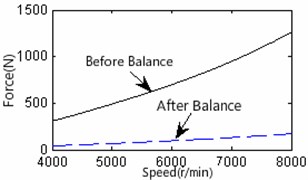
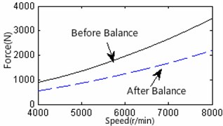
The normal working speed of the single cylinder internal combustion engine is 4000-8000 r/min. In order to analyze the influence of the balance shaft on internal combustion engine vibration at various speeds, the inertial excitation force before and after installing the balance shaft was compared, as shown in Fig. 9.
In Fig. 9, the solid line is the inertial excitation force of the original engine at various speeds. The dotted line is the inertial excitation force of optimized engine with a balanced shaft.
It is obvious that the inertial excitation force of the internal combustion engine increases with speed under normal working speed, and the damping performance of the balance shaft is more obvious with the increase of the rotational speed. Therefore, the vibration reduction design method based on balance shaft for the single cylinder internal combustion engine is effective, significantly improving the vibration of the engine. In addition, the method is easy to implement in engineering, which can provide a reference for other internal combustion engine vibration reduction designs.
Fig. 9Comparison of inertial excitation forces before and after installing the balance shaft of internal combustion engine
a) Excitation force perpendicular to the piston direction
b) Resultant force of ICE body
5. Conclusions
1) In ADAMS/VIEW, the multi-body dynamics model of crank connecting rod mechanism of a single cylinder internal combustion engine was established, and the virtual experimental simulation analysis was carried out. It was found that the results between the analysis and the theoretical calculation results were basically consistent, indicating that the established model is correct and reliable.
2) Starting with the reduce of the inertia excitation force, the uniaxial balance method was used to carry out the vibration reduction design based on the balance shaft. The results showed that the inertial excitation force of the single cylinder internal combustion engine with a balance shaft was significantly reduced, thus improving the vibration situation.
References
-
Xu Zhaokun, Sun Shu Ting, Wu Weiwei Vibration analysis and the location of balance shaft on four-cylinder engine. Noise and Vibration Control, Vol. 6, 2007, p. 50-53.
-
Li Fengqin, Zheng Guangze, Ai Xiao-Yu Analysis of twin balancer shafts system in internal combustion engines. Journal of Vibration and Shock, Vol. 33, Issue 5, 2014, p. 58-63.
-
Fan Wenxin, Li Shuanghu, Yang Guitong Study on a new method of balance shaft mechanism design of engine. Transactions of CSICE, Vol. 27, Issue 6, 2009, p. 557-562.
-
Lee, Yoon H. A study on the balancing of the three-cylinder engine with balance shaft. SAE Technical Paper 2000-01-0601, 2000.
-
Chen Liping, Zhang Yunqing, Ren Weiqun Mechanical System Dynamics Analysis and ADAMS Application Tutorial. Tsinghua University Press, Beijing, China,2005.
-
Yu Feng, Xu Zhongming, Zhang Zhifei Simulation and analysis of ATV vibration comfort based on ADAMS. Machine Design and Research, Vol. 31, Issue 2, 2015, p. 160-163.
-
Lu Jiqing, Meng Sizong Automobile Engine Design. Tsinghua University Press, Beijing, China, 1990.
-
Wu Nan, Liao Ri Dong, Zhang Baocheng Multi-body system dynamics analysis of the crank and connecting rod mechanism in diesel engines. Chinese Internal Combustion Engine Engineering, Vol. 26, Issue 5, 2005, p. 69-73.
-
Li Shuanghu, Fan Wenxin, Yuan Xia The study on the application of balance shaft mechanism in vibration resource control of machine. Modern Manufacturing Engineering, Vol. 4, 2010, p. 128-132.
-
Song Liquan, Wang Wei Study of ellipse equation of inertial force in the motorcycle engines balance. Chinese Internal Combustion Engine Engineering, Vol. 26, Issue 4, 2005, p. 50-52.
-
Ma Zongzheng, Liu Yuxi Balance shaft design of single-cylinder engine base on single-axis balance mechanism. Journal of Machine Design, Vol. 30, Issue 8, 2013, p. 23-24+48.
Cited by
About this article
The authors disclosed receipt of the following financial support for the research, authorship, and/or publication of this article: this study was supported by Chongqing Municipal Education Commission Science and Technology Project (Nos. KJ1603207 and KJQN201803408).
