Abstract
Formerly, torsional vibration of crankshaft in off-highway diesel engine (agricultural machinery) were given little attention at their developmental stages, however with increasing agricultural activities, numerous torsional vibration problems have been noted to occur in agricultural machinery, especially in their diesel engines. This results in engine vibration, crankshaft failure and undesirable engine noise. In this paper, a six-cylinder four-stroke inline diesel engine’s crankshaft model was developed using AVL Excite Designer. After experimentally validating the model, it was used to numerically determine the torsional vibrations of a crankshaft. For the reduction of torsional vibration, two methods of crankshaft improvements were proposed based on simulation results. The first method, is to decrease the inertia of the crank pulley while the second, involves the replacement of the crank pulley with a torsional vibration damper. To ensure minimal engine alterations and cost effectiveness, the second improvement method was adopted for improving torsional vibration. Afterwards, engine radiating noise and surface vibration measurements were conducted to ensure that the required limits were achieved by the improved engine. The simulation, experiment and the improvement process of the crankshaft torsional vibration are documented further in this research. These improvements have applicable values in the developmental or quality enhancement stage of diesel engines used in agricultural machinery.
1. Introduction
As a special form of vibration, torsional vibrations are usually used to describe torsional deformation movements of rotating shafts [1, 2], as in internal combustion (IC) engine crankshaft. Causes of IC engine crankshaft torsional vibration can be categorized in two-fold (i.e. internal and external causes). Internal and external causes of crankshaft torsional vibrations are due to elastic deformations of the crankshaft body and the periodic effect of torques acting on the crankshaft respectively. Hence in brief, crankshaft’s torsional vibration can be defined as the elastic torsional deformations caused by the periodic acting excitation torques on the crankshaft during operations.
With little attention given to torsional vibrations at the developmental stages of off-highway Diesel Engine, several torsional vibration problems such as crankshaft failure, flywheel bolt failure, bearing bush pitting, increasing knock noises of timing gear, decreasing engine power and others [3-5], occurs commonly during operations. Also, since mechanize land cultivation is on the increase globally, the significance of Noise, Vibration and Harshness (NVH) levels from agricultural machinery on their performance are on the rise with high global awareness, currently. Therefore, in this research, to ensure that manufactured crankshafts meet the NVH requirement standard, simulation and experimental studies were carried out to investigate and establish improvement processes for crankshaft torsional vibration reduction [6-8].
2. Harmonic analysis of torsional vibration
2.1. Equivalent model
To calculate crankshaft’s torsional vibration, geometric model that describes crankshaft system characteristics needs to be developed firstly. Geometric models are means used to describe actual system behaviors and are generally accepted if they exhibit high level of precision in describing them irrespective of how simple the model. This is due to the fact that, complete description of actual system behavior with a geometric model is extremely challenging and in most cases, impossible. To calculate torsional vibration frequency and amplitude, the crankshaft of a diesel engine can be simplified as a system consisting of rigid bodies with rotational inertia but no elastic deformation and a shaft segment with elastic deformation but no rotational inertia. Usually, the simplified system is referred to as an equivalent system [9].
Fig. 1Crankshaft equivalent model of six-cylinder inline diesel engine

In this research, a six-cylinder four-stroke inline diesel engine was chosen as the research object. The Crankshaft of the engine is a simplified eight-DOF (degree of freedom) equivalent system (simplified system) as shown in Fig. 1. To ensure dynamic equivalence, both kinetic and potential energies of the simplified system were set with the actual crankshaft values in the vibration process. Below are the descriptions of the parameters in Fig. 1: – moment of inertia of crankshaft front end, - – moment of inertia of crankshaft part (taking into consideration the moments of inertia of the connecting rods and piston assembly), – moment of inertia of flywheel and flange between flywheel and dynamometer, – torsional stiffness of crankshaft front end and first crank web, - – torsional stiffness of crank webs, – torsional stiffness of last crank web and rear end of crankshaft.
From the system dynamics, there are () main mode shapes for the vibration model with lumped masses and nodes ranging from 1 to . For most off-road diesel engines working at low speed as in this research, the main mode shape with a single node is concentrated on analytically. Shown in Fig. 2, is the main mode shape of the off-road diesel engine used in this study.
Fig. 2Main mode shapes of crankshaft torsional vibration (Ⅰ- main mode shape with single node, Ⅱ-main mode shape with two nodes)

2.2. Harmonic analysis
The external cause of torsional vibrations is excitational torques produce by both reciprocating inertia forces and crank throw acting combustion pressures. The excitation torque is a periodic function which according to Fourier’s theory, can be expressed as the sum of an infinite number of harmonic contents with different cycles. Therefore, these harmonic analytical methods that are usually employed in dealing with periodic problems was equally employed in this research.
For the six-cylinder four-stroke inline diesel engine, there is a phase difference during the acting phase of the excitation torques on different crank throws. The phase difference is ( 0.5, 1, 1.5, 2, 2…) in this research. is the corresponding harmonics of the excitational torque.
Excitational torque acting on the 1st crank throw is expressed as:
While the, excitational torque acting on the th crank throw is also expressed as:
where, is the amplitude of the excitational torque and is the firing phase angle between th cylinder and 1st cylinder.
Also, the expression relating the phase difference to the firing phase angle is formulated as:
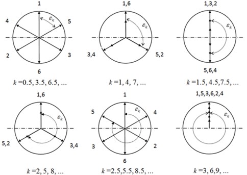
The phase difference can be described using the excitational torques vector diagram shown in Fig. 3. From the diagram, the numbers 1 to 6 describes the respective excitation torques acting on different crank throw. Directional vectors of the 3rd, 6th and 9th harmonic excitation torques are the same and have the maximum influence on the crankshaft’s torsional vibration. While, the 1.5th, 4.5th and 7.5th harmonics exhibits some degree of influence on the crankshaft’s torsional vibration because of their opposite phase acting excitational torques, however the other harmonics are chaotic in phase and hence do not produce strong resonance [10].
Fig. 3Vector diagram of excitation torques
3. Simulation of torsional vibration
Since it is difficult and costly to reduce the torsional vibration of a crankshaft designed for a diesel engine, torsional vibration analysis and torsional reduction should be taken into account during the design phase of the crankshaft as it holds high influence on the strength of the crankshaft’s related parts [11, 12]. In this paper, torsional vibration of a crankshaft in a six-cylinder four-stroke inline diesel engine is simulated using AVL Excite Designer, where the mathematical model of the torsional vibration is solved by the extending Holzer Method. As described in [9] for a multi-mass system with damped forced vibration, the equation of motion is expressed as:
where, is the moment of inertia of mass , is the damping torque in the shaft segment between mass () and , is the mass external damping torque, is the shaft segment stiffness between mass () and , is the excitation torque amplitude, is the excitation torque angular frequency, is the initial phase of the excitation torque, is the angular displacement and and are the angular velocity and acceleration respectively.
In matrix form the equation of motion expressed in Eq. (4), takes the form:
where, is the inertial matrix, is the damping matrix, is the stiffness matrix, is the excitation torque vector and , and are the angular displacement, velocity and acceleration vectors respectively:
3.1. Torsional model
The main parameters of the diesel engine are as shown in Table 1. The three dimensional (3D) geometric model of crankshaft consisting of the flywheel, crank pulley, connecting rod, piston, bearing and others are shown in Fig. 4.
Table 1Major parameters of the diesel engine to study
Pattern | Water cooled, inline and 6-cylinder |
Cylinder bore and stroke | 110 mm×125 mm |
Displacement | 7.1 L |
Rated power/speed | 118 kw / 2200 r/min |
Intake type | Supercharge and inter-cooling |
With the AVL EXCITE DESIGNER, all parts of the crankshaft were connected systematically (see Fig. 5). Properties such as the total mass, moment of inertia, and axial stiffness based on the equivalent system theory were set with the appropriate selection of sub models within the software. However, the moments of inertia of the different parts of the crankshaft were determine with a CAD system. Shown in Table 2 are the crankshaft related parts parameters.
Fig. 4Three-dimensional model of the crankshaft
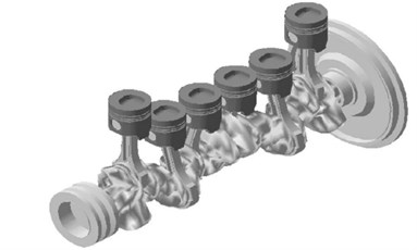
Fig. 5Simulation model of crankshaft torsional vibration
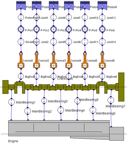
Table 2Material parameters of related parts
Related part | Material | Elastic modulus | Poisson ratio |
Crankshaft | 42CrMoA | 2.12e5 MPa | 0.28 |
Crank pulley and flywheel | HT250 | 1.03e5 MPa | 0.26 |
Hub | 40Cr | 2.11e5 MPa | 0.277 |
3.2. Measurement of explosive combustion pressure
To accurately determine the excitation torques, explosive combustion pressures were measured from cylinder pressure sensor installed in the combustion chambers at locations determined by the CAD model shown in Fig. 6. The cylinder pressure sensors used in the measuring process are products of Kistler Instrument Company (6053CCsp120 model number). The angular displacement of the crankshaft was measured by an encoder which produces 720 pulses per cycle with sampling interval of 0.5 degrees. Also used in the measuring process is a front filtering function data acquisition system.
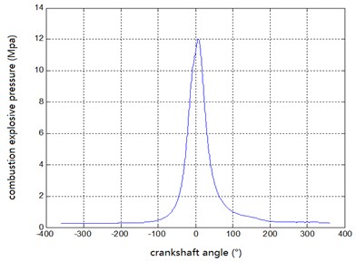
At a set engine working condition, cylinder pressures for 20 work cycles were measured and averaged. At 2200 r/min engine full load, the relationship between pressure change and variations in crankshaft angle were established (Fig. 7). That is, the relationship between explosive combustion pressures and crank angles during the working process can be seen in Fig. 7.
Fig. 6Installation of cylinder pressure sensor on cylinder head
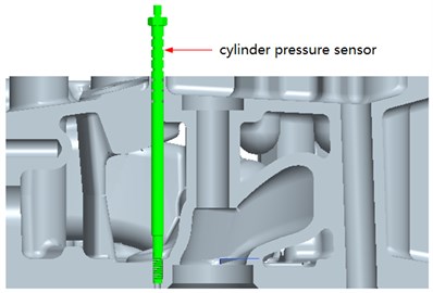
Fig. 7Curve of explosive combustion pressure at 2200 r/min at full load state
4. Measurement of torsional vibration
Torsional vibration of crankshaft is usually determined by measuring the torsional angle at the front end of the crankshaft. In the case of the main mode shape with single node, the maximum torsional angle of the crankshaft’s front end is usually recorded between the flywheel and the adjacent crank throw, where the single node is located.
Torsional angle was computed by measuring the instantaneous angular velocity fluctuations relative to average angular velocity and then integrating to get the torsion angle of the crankshaft. The crankshaft angular velocity and the rotational speed are normally computed theoretically. That is, angular velocity of crankshaft is determined using measuring techniques such as laser measurement, magneto-electric measurement, photoelectric measurement and others [13, 14]. However, in the case of measuring, angular velocity requires higher sampling frequency than rotational speed. The set number of teeth on the gear or the grating number of encoder needs to be twice as much as the required harmonics. For internal combustion engine, the maximum harmonics required should be at most 10, due to the quick reduction in vibration energy associated with increment in harmonics.
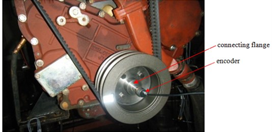
Fig. 8 shows the test setup used in determining crankshaft torsional vibration conducted at engine full load during acceleration and deceleration processes. However, the difference in measurements during acceleration and deceleration processes are usually negligible. To ensure uniform change in rotational speed, acceleration and deceleration processes were automatically controlled for 90 seconds during experiments and also rotational speed were controlled from 1200 to 2260 r/min.
Fig. 8Measurement of torsional vibration of crankshaft
5. Comparison between simulation and experiment
To analyze torsional vibration of the crankshaft, FFT analysis of the crankshaft torsional angle was conducted and the results (in Color-map) is shown in Fig. 9, where a graph of frequency plotted on the horizontal axis and engine rotational speed on the vertical axis are displayed. The frequency, rotational speed and torsional angle units are Hz, r/min and degrees respectively. The slanted lines in the diagram represent different torsional vibration harmonics.
Fig. 9Color-map of the measured torsional vibration signals
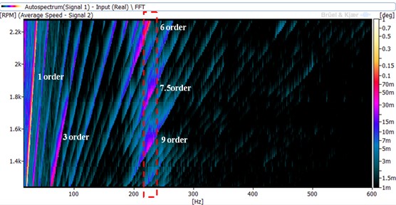
The magnitude of the torsional vibrations at the various harmonics are reflected through the color codes in Fig. 9. It can be seen that, the 1st, 3rd, 6th, 7.5th and 9th harmonics are relatively high which are due to the following. For the 1st harmonic, the high recording obtained is as a result of misalignment of the coupling encoder at the crankshaft front end, hence can be ignored. The high magnitude of the 3rd harmonic (highest excitational torque relative to the other harmonics) results in roll-vibrations of the shaft between the dynamometer and the engine. However, the 3rd harmonic’s decreasing magnitude with rising engine speed means that it cannot be categorized as a torsional vibration. The occurrence of roll-vibration therefore means that, the shaft can be considered as a rigid body since the shaft masses oscillates with the same amplitude and in phase.
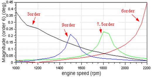
In determining the relationship between the harmonics and speed, segments of the color-map in Fig. 9 were further analyzed as shown in Fig. 10. From the figure, it can be seen that the harmonics of the 6th, 7.5th and 9th are very significant. From about 2000 r/min engine speed, the 6th harmonic increases with increasing engine speed till peak resonance is attained (at maximum speed). For the 7.5th and 9th harmonics, resonances are attained during engine speed acceleration or deceleration since resonance occurs before maximum engine speed is reached in both cases. Resonating frequencies of the 6th, 7.5th and 9th harmonics occurs at 227 Hz frequency (see Fig. 11), representing the crankshaft’s first natural frequency. For the 4.5th harmonic, resonance was not attained within the working speed range of the engine, implying that it has relatively small vibration energy.
Fig. 10Harmonic and speed curve relationships (obtained by measurement)
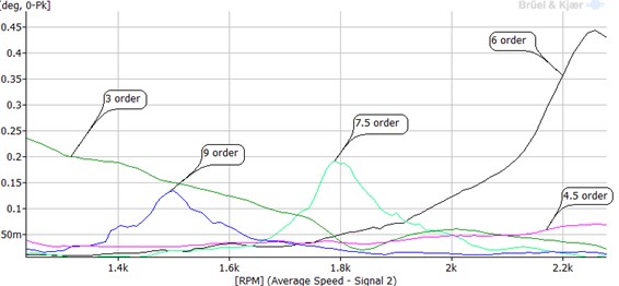
Fig. 11Critical speed obtained from simulation
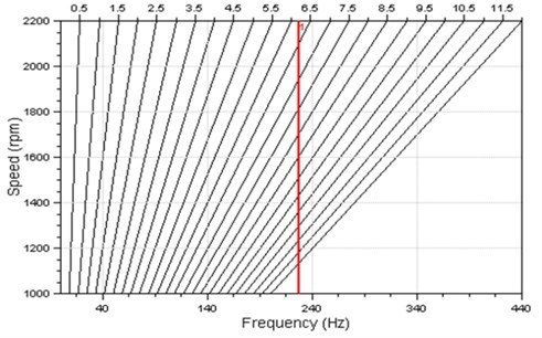
Shown in Fig. 11 is the critical speed diagram obtained from simulation. From the diagram, intersections between the red straight line and the slanting lines represents the critical speed points of the different harmonics. Comparing the critical speed in Fig. 11 to the resonance speed in Fig. 9, it can be seen that at the various harmonics, the recorded readings are the same. In addition, the first natural frequency of the crankshaft from both simulation and experiment are equally consistent with each other.
The relationships between the harmonics and speed as obtained from simulation are shown in Fig. 12. The resonance speeds and torsional angle amplitudes obtained from both experiments and numeric (from Fig. 10 and Fig. 12) are shown in Table 3. The plus sign "+" shows that the torsional vibration of the 6th harmonic increases with increasing speed. Also from the 6th harmonic, experimental resonating speed exceed the simulated resonating speed. It is clear from the table that the simulation and experiment results agrees with each other adequately, hence validating the developed crankshaft geometric model.
Table 3Experimental and simulation results comparison
Experimental result | Simulation result | |||
Resonance speed (r/min) | Torsion angle (degree) | Resonance speed (r/min) | Torsion angle (degree) | |
The 6th harmonic | 2252 | 0.44 | 2200+ | 0.45+ |
The 7.5th harmonic | 1795 | 0.21 | 1800 | 0.23 |
The 9th harmonic | 1494 | 0.14 | 1500 | 0.21 |
Fig. 12Harmonic and speed curve relationships (obtained by simulation)
6. Torsional vibration reduction in different ways
To determine whether the torsional stress is within required limits, the torsional stress determined from the measured torsional angle is compared to the allowable torsional stress limits. After which, vibration reduction measures could be sought, if needed. In practice, torsional angle amplitudes are used to directly determine whether torsional vibration requirements are met. In relation to strength, the single order vibration amplitude of a six-cylinder inline diesel engine should not exceed 0.2 degrees. Also with noise reduction, the single order vibration amplitude should not exceed 0.1 degrees, otherwise torsional vibration may be the major excitational source for engine noise.
From both simulation and experiment, the 6th harmonic vibration amplitude was more than 0.4 degrees within the working speed limits of the engine, while the 7.5th and 9th harmonics vibration amplitudes were around 0.2 degrees within the same speed limits. Therefore, vibration reduction measures have to be taken for the crankshaft.
6.1. Moment of inertia adjustment for the crank pulley
The validated geometrical model of the torsional vibration, through numerical simulation is used to propose various improvement measures. The measures, implemented on the numerical model, were tested numerical by conducting simulations at the same conditions. After which it was observed that, the developmental cycle could be shorten as a result. Shortening of the developmental process leads to production cost reduction.
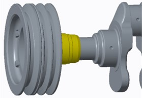
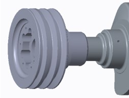
One method that could be adopted to reduce the torsional vibration is to improve the natural frequency of torsional vibration first and foremost, through increasing shaft stiffness or decreasing the inertia of lumped masses. This method was not considered because of high relative cost associated with it (i.e. it requires change in the processing scheme to increase shaft stiffness). To decrease the inertia of the lumped mass, the lumped mass constituting the various parts (flywheel and crank pulley) have to be analyzed individually. As the energy storage unit, the flywheel’s inertia could not be easily altered but that of the crank pulley can be altered to meet the required strength condition. From the simulation results shown in Table 4, the high inertia of the initial crank pulley is reduced to 0.027 kg·m2 from 0.067 kg·m2. Shown in Fig. 13 are the initial crank pulley and the reduced crank pulley.
Table 4Simulation results of different crank pulleys
Moment of inertia (kg·m2) | First natural frequency (Hz) | Torsional vibration amplitude (degree) | Maximal dynamic torque of the crank pulley end (N·m) | ||
The 6th harmonic | The 7.5th harmonic | The 9th harmonic | |||
0.067 | 227 | 0.45 | 0.23 | 0.21 | 1500 |
0.027 | 260 | 0.12 | 0.17 | 0.15 | 400 |
Fig. 13Crank pulley models (left: initial crank pulley; right: improved crank pulley)
a)
b)
Through simulation, the first natural frequency of the torsional vibration was increased to 260 Hz and the maximum torsional vibration amplitude of the 6th harmonic was reduced to 0.12 degrees within the working speed limit of the engine. In addition, the 6th harmonic, the resonance amplitudes of the 7.5th harmonic and the 9th harmonic were also reduced (see Table 4).
6.2. Fitting torsional vibration damper for crankshaft
The diesel engine used in this research is mainly used for corn harvesting during farming activities. The crank pulley is also used to drive or walk equipment’s during corn harvesting, except fans, generators and other engine attachments. This makes changing the size of the crank pulley not desirable, however the crank pulley can rather be replaced by a torsional vibration dumper without necessarily changing the size. By this method the torsional vibrations can be reduced effectively.
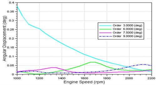
After careful consideration, torsional vibration dampers were adopted to be used in torsional vibration reduction, due to cost and reliability issue. Through the same computation procedures, the natural frequency ratio and inertia ratio of the torsional vibration damper and the crankshaft were computed to be 0.84 and 0.34 respectively. As shown in the simulation results of the harmonics torsional vibrations (Fig. 14), the 6th, 7.5th and 9th harmonic vibration amplitudes did not exceed 0.11 degrees. The maximum vibration amplitude of the 6th harmonic is around 0.06 degrees.
Fig. 14Simulation results after installing torsional vibration damper
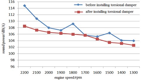
With regards to design limitations, the size of the torsional vibration damper should be the same as that of the initial crank pulley for easy replacement. Therefore, in this regard, the torsional vibration damper shown in Fig. 15 was designed and used in replacing the crank pulley which led to the reduction in torsional vibration. This subsequently resulted in significant reductions in engine radiating noise and surface vibrations. After the replacements, the engine radiating noise and surface vibrations were respectively measured in accordance with the procedures specified in GB/T 1859-2000[15] and GB/T 7184-2008[16]. The results obtained are as shown in Fig. 16 and Table 5 respectively.
Table 5Comparison of engine surface vibration under rated condition
Before installing torsional damper | After installing torsional damper | |
Vibration intensity (mm/s) | 42.6 | 27.2 |
Fig. 15Torsional vibration damper
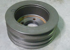
Fig. 16Comparison of engine radiated noise under external characteristic condition
7. Conclusions
As one of the causes of IC engine noise and vibration in off-highway machinery, torsional vibrations from an engine crankshaft were numerically investigated using an experimentally validated model in this study. From the investigation, two improvement methods for reducing crankshaft torsional vibration were observed. The methods together with the numerical procedures and analysis performed during the study are as follows:
1) The numerical model of the crankshaft geometry was developed using the principle of equivalent system theory. After the successful validation of the model, it was used to determine the moment of inertia of lumped masses and the stiffness of the various shafts that connect the lumped masses respectively. To ensure accurate simulation results, the moment of inertia of the flange located between the flywheel and the dynamometer was taken into account. The moment of inertia contributed by the timing gears was ignored, because it accounts for less than 10 % of the whole unit’s moment of inertia.
2) Based on the crankshaft torsional vibration simulation results from the experimentally validated model, two improvement methods for the reduction of torsional vibrations were proposed. One was to decrease the inertia of the crank pulley while the other was to replace the crank pulley with a torsional vibration damper. Both methods satisfactory achieved the required vibration reduction through different engine manufacturing phases.
References
-
Matyja T., Łazarz B. Modeling the coupled flexural and torsional vibrations in rotating machines in transient states. Journal of Vibroengineering, Vol. 16, Issue 4, 2014, p. 1911-1924.
-
Liang X., et al. Axial vibration source identification of engine crankshaft based on auto-regressive and moving average model and analytic hierarchy process method. Journal of Vibration and Control, Vol. 20, Issue 8, 2014, p. 1185-1198.
-
Pasricha M. S., Carnegie W. D. Diesel crankshaft failures in marine industry – a variable inertia aspect. Journal of Sound and Vibration, Vol. 78, 1981, p. 1347-354.
-
Pang J., et al. Automotive Noise and Vibration – Principle and Application. Beijing Institute of Technology Press, Beijing, 2006, (in Chinese).
-
Mostafa W., et al. Low speed bearings fault detection and size estimation using instantaneous angular speed. Journal of Vibration and Control, Vol. 22, Issue 15, 2014, p. 3413-3425.
-
Ochiai K., Nakano M. Relation between crankshaft torsional vibration and engine noise. SAE Technical Paper, No. 790365, 1979.
-
Kubozuka T., et al. Analytical study on engine noise caused by vibration of the cylinder block and crankshaft. SAE Technical Paper, No. 830346, 1983.
-
Ide S., et al. Improvement of engine sound quality through a new flywheel system flexibly mounted to the crankshaft. SAE Technical Paper, No. 900391, 1990.
-
Wang Q. Torsional Vibration of Engine Crankshaft. Dalian University of Technology Press, Dalian, 1991, (in Chinese).
-
Zhou L. B., et al. Internal Combustion Engine. China Machine Press, Beijing, 2010, (in Chinese).
-
Carrato P. J., Fu C. C. Modal Analysis Techniques for Torsional Vibration of Diesel Crankshafts. SAE Technical Paper, No. 861225, 1986.
-
Henry J. P., Toplosky J., Abramczuk M. Crankshaft durability prediction – a new 3-D approach. SAE Technical Paper, No. 920087, 1992.
-
Wang P. S., Davies P., Starkey J. M. A torsional vibration measurement system. IEEE Transactions on Instrumentation and Measurement, Vol. 41, Issue 6, 1992, p. 803-807.
-
Halliwell N. A. The laser torsional vibrometer: a step forward in rotating machinery diagnostics. Journal of Sound and Vibration, Vol. 190, Issue 3, 1996, p. 399-418.
-
GB/T 1859-2000. Reciprocating Internal Combustion Engines-Measurement of Emitted Airborne Noise-Engineering Method and Survey Method, (in Chinese).
-
GB/T 7184-2008. Measurement Method of Vibration for Small and Medium Power Diesel Engines, (in Chinese).
Cited by
About this article
This work is supported by Chinese State Key Research and Development Plan (2016YFD0700702) and Chinese Science and Technology Support Plan (2014BAG09B01).
Liming Sun was the principal person to complete the work involved in this paper and completed the article writing. Fuqiang Luo performed the theory analysis of torsional vibration. Tansu Shang designed the experiment to reduce torsional vibration. Hongtao Chen participated in the testing work involved in this paper. Adams Moro performed revision of the article language.
