Abstract
World-wide constraints on the supply of fossil fuel resources exist in conjunction with stringent environmental constraints. Therefore, it is very important to develop advanced technologies to reduce fuel consumption. The transmission efficiency of an automatic vehicle is low because of the torque converter. Hence, in this study, a power reflux hydraulic transmission system (PRHTS) was proposed. It is important to avoid the phenomenon of resonance in a powertrain with a PRHTS, and thus it is necessary that the resonance point of a powertrain with a PRHTS does not exist in the resonance region of the engine. A dynamic and mathematical model of a powertrain with a PRHTS was developed to study the resonance characteristic of the powertrain. The amplitude-frequency characteristic curve of a powertrain for different speed ratios was obtained. The effect of torsional stiffness of the coupling and engine shock absorber on the amplitude-frequency characteristics of a powertrain with a PRHTS were examined. The simulation result indicated that it was necessary to exclude the resonance frequencies of the powertrain with a PRHTS from the operation range of the engine.
1. Introduction
A powertrain has immediate impact on the power performance, fuel economy, and emission performance of a vehicle [1-3]. Currently, several vehicles use an automatic transmission in a powertrain to achieve drive-ability, torque amplification, and torsional damping characteristics [4]. An automatic transmission mainly consists of a torque converter and a power shift transmission [5]. The torque converter is the most important element of an automatic transmission. The automatic transmission can de-couple an engine from the wheels and attenuate the torque fluctuation of an engine. However, the efficiency of the automatic transmission is lower than manual transmission [6]. Hence, it is extremely important to improve the efficiency of torque converter. This study involved proposing a PRHTS using a torque converter that was appropriate for construction vehicle [7-9]. Based on the requirements of the construction vehicle, it was necessary for the torque converter to possess a high starting torque ratio and a wide high efficiency range. Therefore, in the study, a double stator torque converter with a high starting torque ratio and a wide high efficiency range exceeding 80 % was used [10-13].
The motion of an engine crankshaft is periodic, and thus an engine has a resonance region. With respect to the six cylindered diesel engine, the rational range of rotating frequencies of an engine is between 40 Hz and 150 Hz (800-3,000 rpm) [14]. It is necessary to avoid resonance phenomenon for a powertrain with a PRHTS. Therefore, the resonance point of a powertrain with a PRHTS should not exist in the resonance region of the engine. Hence, there is no research conducted on the analysis of a PRHTS. Thus, it is important to investigate the resonance characteristics of a powertrain with a PRHTS. A previous study examined the resonance characteristics of a PRHTS [9]. However, the vehicle powertrain were an integrated whole. Hence, it was not sufficient to analyze the PRHTS by itself, and it is essential to analyze the resonance characteristics of a powertrain with a PRHTS. An examination of the amplitude-frequency characteristics of a powertrain with a PRHTS is more complicated than a PRHTS because a powertrain with a PRHTS involves more components and degrees of freedom. In the present study, a dynamic model of a powertrain with a PRHTS was established, and a simulation was conducted to examine the amplitude-frequency characteristics of the powertrain with a PRHTS for different speed ratios. The simulation results indicated that the rational range of rotating frequencies of an engine has two resonance frequencies. The effects of the torsional stiffness of coupling and engine shock absorber on the amplitude-frequency characteristics of the powertrain with the PRHTS were examined to exclude the resonance frequencies. Finally, the resonance frequencies of the powertrain with a PRHTS were successfully moved out from the rational range of rotating frequencies of an engine.
2. The basic structure and operating principle of PRHTS
Variator elements (such as chain belt, torque converter, hydrostatic transmission, and electric converter) involve low efficiency, and thus a PRHTS could improve efficiency by dividing the input power of the system into two parts [15-20]. A part of the input power is transmitted by high efficiency gears, while the other part is transmitted by a low efficiency variator element. The power transmitted by the variator element decreases, and thus the transmission system efficiency improve [21-24].
Fig. 1A schematic and power flow of the PRHTS. T: turbine; P: pump; St1, St2: stators; r: ring gear; c: carrier; s: sun gear
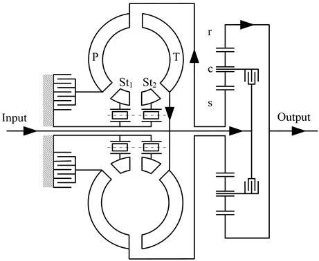
Fig. 1 shows the schematic of a PRHTS. A major characteristic of a PRHTS involves the torque converter with a reflux power path that comprises the turbine that is connected to the input shaft of the transmission system and the pump that is connected to the sun gear of the planetary gear train. The power flow of a PRHTS is shown in Fig. 1 and is described as follows. First, the power of the engine enters the input shaft of the PRHTS (as shown at the left side of Fig. 1). The power is then transferred into the carrier of the planetary gear train. Most of the power is transmitted into the ring gear (at the right side of Fig. 1), which corresponds to the power split characteristics of the planetary gear train. The remainder of the power is termed as reflux power, and it enters the pump of the torque converter via the sun gear. The reflux power enters the input shaft of the PRHTS by torque amplification of the torque converter. The reflux power joins with the output power of the engine, and the resulting combination enters the carrier. Therefore, the output shaft of the transmission system has a continuous variable speed by means of the torque converter, while the speed of the engine is constant. Therefore, a PRHTS is a continuous variable transmission system.
3. A dynamic model of a powertrain with a PRHTS
3.1. The powertrain equivalent system
A vehicle powertrain is a very complex multi-body system. The front end of the powertrain consists of the engine, and the rear of the powertrain consists of the driving wheel. The vehicle powertrain includes moment of inertia and torsional stiffness that are unevenly distributed, and it corresponds to a multi mass elastic torsional vibration system. Therefore, multi-body system analysis involves certain difficulties. Thus, an equivalent system must be defined to focus on the analysis of torsional vibration of the powertrain. In the equivalent system, all parts of a rotating machine are converted into coaxial rotation. Additionally, it involves the following assumptions with respect to the powertrain:
1) The vehicle operates in a stable condition without considering the engine start, shift, and other transient conditions;
2) The large elastic and inertia components are simplified as springs;
3) The small elastic and large inertia components are simplified as rigid bodies;
4) The effect of bending and longitudinal vibrations on the torsional vibration of powertrain is not considered;
5) The torsional stiffness and the moment of inertia of the components are simplified as an adjacent rigid body;
6) The torsional stiffness and the moment of inertia of the free rotating components are not considered;
7) The equivalent transformation of the torsional stiffness and the moment of inertia of each shaft is performed;
8) The influence of the ancillary equipment is not considered;
9) The vehicle translation parts are translated into wheels.
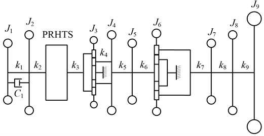
As shown in Fig. 2, the powertrain equivalent system consists of the moment of inertia, the torsional stiffness, and damping;
Fig. 2The powertrain equivalent system
3.2. Dynamic modeling of a PRHTS
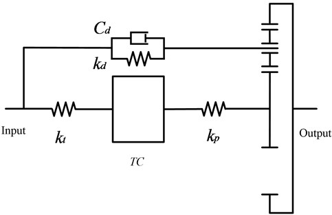
Fig. 3 is the dynamic model of a PRHTS. A previous study established a dynamic model of a PRHTS [9]. Therefore, the present study does not examine details of a PRHTS dynamic model. As shown in our previous papers [9], it can be seen that the influence of the two dynamic models of the torque converter was minor for simulation result of the amplitude-frequency characteristic. In order to conveniently calculate, the quasi-static model is used to establish the dynamic model of the powertrain with a PRHTS.
Fig. 3The dynamic model of the PRHTS
3.3. The equivalent moment of inertia and equivalent torsional stiffness of the powertrain
Moment of inertia is a measure of the rotational inertia of an object. Different rotating parts have different rotational speeds due to the transmission speed ratio. For the purpose of convenience in the computation, it is necessary for different rotating parts to be transformed into inertia of the same rotational speed. Similarly, it is also necessary to transform the torsional stiffness.
3.3.1. The computational method of the equivalent moment of inertia
Generally, engine speed is the transformation benchmark of equivalent moment of inertia. Each component of a powertrain is transformed into engine speed. The transformation process follows the principle of conservation of energy.
The kinetic energy of the component of the powertrain is expressed as follows:
The equivalent kinetic energy of the th component must be equal to the original kinetic energy as given by the following expression:
The principle of kinetic energy equivalent results in the following expression:
The equivalent moment of inertia of the vehicle translation is expressed as follows:
3.3.2. Computation of equivalent torsional stiffness
Equivalent elastic deformation energy of the th component must be equal to the original elastic deformation energy and is expressed as follows:
3.4. Equilibrium equation of the dynamics of a powertrain with a PRHTS
Based on Fig. 2, the equilibrium equations of the dynamics of a powertrain with a PRHTS are given by the following expressions:
4. A six cylindered diesel rational range of rotating frequencies of an engine
The mode of motion of an engine crankshaft involves reciprocating motion. Therefore, the torque of a cylinder changes with the position of the crankshaft and creates a periodic variation with time. The Fourier series representation of the torque of a cylinder is as follows:
Based on Eq. (19), the torque of a cylinder consists of average torque and torque harmonic parts. The excitation torque of a powertrain is the sum of the torque of each cylinder.
With respect to the engine, the vibration times per revolution is influenced by the number of cylinders in the engine and the number of strokes of the engine. The formula for calculating the vibration times per revolution is as follows:
The formula for calculating the vibration frequency of the engine is as follows:
With respect to a six-cylindered four-stroke diesel engine, the vibration times per revolution is three as calculated by Eq. (20). Based on Eq. (21), the vibration frequency of a six-cylindered diesel engine with a rotational speed of 800-3,000 rpm corresponds to 40-150 Hz.
5. Amplitude-frequency characteristics of a powertrain with PRHTS
5.1. Amplitude-frequency characteristic of a powertrain with a PRHTS with different speed ratios
A dynamic simulation model of a powertrain with a PRHTS based on MATLAB was constructed. The equilibrium equations of the dynamics of the powertrain with a PRHTS are reduced as first order explicit differential equations. The frequency of the sine wave was swept at 1 Hz/sec from 10 Hz to 600 Hz. Signal processing of the model outputs involved computing a frequency response function given by the following expression:
where the input corresponds to dynamic engine torque, and the output corresponds to the dynamic vehicle translation torque.
The Runge-Kutta integral method was adopted to derive the frequency response function. Fig. 4 shows the amplitude-frequency characteristic curves, and dashed frame indicates operation range (40 Hz-150 Hz) when the speed ratios of the PRHTS correspond to 0.1, 0.5, 0.7, and 0.9. There have two resonance frequencies in rational range of rotating frequencies of an engine. It was observed that speed ratios do not impact the resonance frequencies of powertrain.
The resonance frequencies of powertrain with different speed ratios are identical, and thus it is sufficient to study a certain speed ratio to represent the resonance frequencies of powertrain. The resonance frequencies with all speed ratios are not in rational range of rotating frequencies of an engine when the resonance frequencies of powertrain are moved out from rational range of rotating frequencies of an engine.
5.2. Changing the amplitude-frequency characteristic of the powertrain with a PRHTS
As shown in Fig. 4, it was observed that there were two resonance points in the operation range of the engine. It was necessary to change the components’ parameters of the powertrain with a PRHTS to move the resonance point from rational range of rotating frequencies of an engine. It is only easy to change parameters of the coupling of PRHTS and the engine shock absorber throughout the powertrain with a PRHTS. It is necessary to analyze the torsional stiffness. Thus, the effects of the torsional stiffness of the coupling and engine shock absorber on the powertrain with a PRHTS amplitude-frequency characteristic were examined.
5.2.1. Changing the torsional stiffness of the coupling
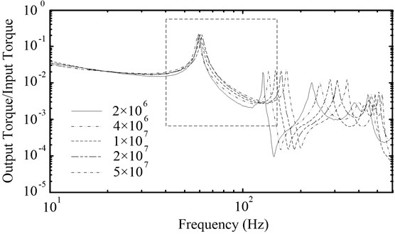
Fig. 5 is amplitude-frequency characteristic curves of powertrain in which the torsional stiffnesses corresponded to 2×10⁶, 4×10⁶, 1×10⁷, 2×10⁷ and 5×10⁷ N·m·rad-1, respectively. It was observed that higher resonance frequency of powertrain increased with the torsional stiffness of the coupling in rational range of rotating frequencies of an engine. However, the lower resonance frequency was not essentially changed. Therefore, the torsional stiffness of the coupling mainly affected the higher resonance frequency of the powertrain with a PRHTS. When the torsional stiffness exceeded 1×10⁷ N·m·rad-1, the higher resonance frequency of the powertrain with a PRHTS was moved out from rational range of rotating frequencies of an engine. Therefore, it is necessary for the torsional stiffness of the coupling to exceed 1×10⁷ N·m·rad-1.
Fig. 4The amplitude-frequency characteristic curves of the powertrain with a PRHTS with different speed ratio
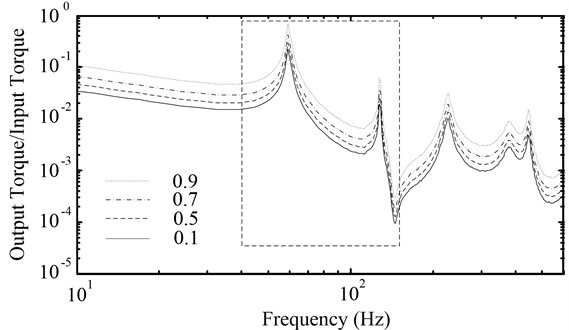
Fig. 5The amplitude-frequency characteristic curves of powertrain with different torsional stiffnesses
5.2.2. Changing the torsional stiffness of engine shock absorber
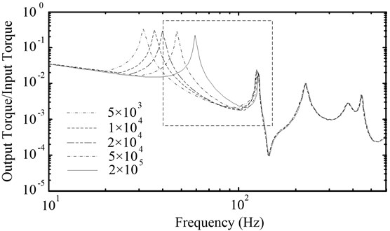
Fig. 6 is the amplitude-frequency characteristic curves of the powertrain with a PRHTS in which the torsional stiffnesses of engine shock absorber corresponded to 5×10³, 1×10⁴, 2×10⁴, 5×10⁴ and 2×10⁵ N·m·rad-1. It was observed that lower resonance frequency of powertrain increased with the torsional stiffness of the engine shock absorber in the rational range of rotating frequencies of an engine. However, higher resonance frequency was not essentially changed. Therefore, the torsional stiffness of the engine shock absorber mainly affected the lower resonance frequency of the powertrain with a PRHTS. When the torsional stiffness was less than 2×10⁴ N·m·rad-1, the lower resonance frequency of the powertrain with a PRHTS is moved out from rational range of rotating frequencies of an engine. Therefore, it is necessary for torsional stiffness of the engine shock absorber to be less than 2×10⁴ N·m·rad-1.
Fig. 6The amplitude-frequency characteristic curves of the powertrain with a PRHTS with different torsional stiffnesses of engine shock absorber
6. Conclusions
In this study, the PRHTS was introduced to improve the fuel economy. The analysis indicated the basic structure and operating principle of the PRHTS. The dynamic model of the powertrain was established. The following main conclusions were obtained from the paper:
1) The simulation results indicated that the speed ratios do not impact the resonance frequencies of powertrain. However, amplitude increased with speed ratios in the rational range of rotating frequencies of an engine. Hence, the torsional damping of powertrain increased during vehicle starting.
2) The torsional stiffness of coupling mainly affected higher resonance frequency of the powertrain. However, the torsional stiffness of the engine shock absorber mainly affected the lower resonance frequency.
Hence, it is necessary to exclude the resonance frequencies of the powertrain with a PRHTS from a rational range of rotating frequencies of an engine by modifying torsional stiffness of coupling and engine shock absorber.
References
-
G. Kouroussis, P. Dehombreux, and O. Verlinden, “Vehicle and powertrain dynamics analysis with an automatic gearbox,” Mechanism and Machine Theory, Vol. 83, pp. 109–124, Jan. 2015, https://doi.org/10.1016/j.mechmachtheory.2014.09.009
-
F. Meng, H. Chen, T. Zhang, and X. Zhu, “Clutch fill control of an automatic transmission for heavy-duty vehicle applications,” Mechanical Systems and Signal Processing, Vol. 64-65, pp. 16–28, Dec. 2015, https://doi.org/10.1016/j.ymssp.2015.02.026
-
F. Meng, G. Tao, and H. Chen, “Smooth shift control of an automatic transmission for heavy-duty vehicles,” Neurocomputing, Vol. 159, pp. 197–206, Jul. 2015, https://doi.org/10.1016/j.neucom.2015.02.004
-
J.-H. Lee and H. Lee, “Dynamic simulation of nonlinear model-based observer for hydrodynamic torque converter system,” in SAE 2004 World Congress and Exhibition, Mar. 2004, https://doi.org/10.4271/2004-01-1228
-
S. M. Park, T. W. Park, S. H. Lee, S. W. Han, and S. K. Kwon, “Analytical study to estimate the performance of the power shift drive (PSD) axle for a forklift,” International Journal of Automotive Technology, Vol. 11, No. 1, pp. 49–56, Feb. 2010, https://doi.org/10.1007/s12239-010-0007-3
-
M. A. Kluger and D. M. Long, “An overview of current automatic, manual and continuously variable transmission efficiencies and their projected future improvements,” in International Congress and Exposition, Mar. 1999, https://doi.org/10.4271/1999-01-1259
-
H. Wang, D. Y. Sun, and D. T. Qin, “A new continuously variable transmission system applied to transmission system of the roadheader’s cutting unit,” Proceedings of the Institution of Mechanical Engineers Part C-Journal of Mechanical Engineering Science, Vol. 231, pp. 3590–3600, Oct. 2017.
-
H. Wang and D. Sun, “Optimal matching between a diesel engine and a PRHTS transmission,” Journal of the Brazilian Society of Mechanical Sciences and Engineering, Vol. 39, No. 9, pp. 3375–3387, Sep. 2017, https://doi.org/10.1007/s40430-017-0741-9
-
D. Sun, H. Wang, and D. Qin, “Resonance characteristics analysis of the power reflux hydraulic transmission system,” Journal of Vibroengineering, Vol. 19, No. 1, pp. 49–60, Feb. 2017, https://doi.org/10.21595/jve.2016.17191
-
H. Wang and D. Sun, “Theory and application on power-cycling variable transmission system,” Journal of Mechanical Design, Vol. 139, No. 2, Feb. 2017, https://doi.org/10.1115/1.4035055
-
Y. You, D. Sun, and D. Qin, “Shift strategy of a new continuously variable transmission based wheel loader,” Mechanism and Machine Theory, Vol. 130, pp. 313–329, Dec. 2018, https://doi.org/10.1016/j.mechmachtheory.2018.08.004
-
Y. You, D. Sun, D. Qin, B. Wu, and J. Feng, “A new continuously variable transmission system parameters matching and optimization based on wheel loader,” Mechanism and Machine Theory, Vol. 150, p. 103876, Aug. 2020, https://doi.org/10.1016/j.mechmachtheory.2020.103876
-
Y. You, D. Sun, and D. Qin, “Research on vehicle starting control based on reflux power condition,” Mechanism and Machine Theory, Vol. 134, pp. 289–307, Apr. 2019, https://doi.org/10.1016/j.mechmachtheory.2019.01.003
-
T. Park, J. Song, J. Jang, and I. Joo, “Dynamic analysis of damper system in torque converter,” in Asia Pacific Automotive Engineering Conference, Aug. 2007, https://doi.org/10.4271/2007-01-3749
-
G. Mantriota, “Power split continuously variable transmission systems with high efficiency,” Proceedings of the Institution of Mechanical Engineers, Part D: Journal of Automobile Engineering, Vol. 215, No. 3, pp. 357–358, Mar. 2001, https://doi.org/10.1243/0954407011525692
-
G. Mantriota, “Infinitely variable transmissions with automatic regulation,” Proceedings of the Institution of Mechanical Engineers, Part D: Journal of Automobile Engineering, Vol. 215, pp. 1267–1280, 2001.
-
G. Mantriota, “Theoretical and experimental study of a power split continuously variable transmission system Part 1,” Proceedings of the Institution of Mechanical Engineers, Part D: Journal of Automobile Engineering, Vol. 215, No. 7, pp. 837–850, Jul. 2001, https://doi.org/10.1243/0954407011528428
-
G. Mantriota, “Performances of a series infinitely variable transmission with type I power flow,” Mechanism and Machine Theory, Vol. 37, No. 6, pp. 579–597, Jun. 2002, https://doi.org/10.1016/s0094-114x(02)00017-4
-
G. Mantriota, “Fuel consumption of a vehicle with power split CVT system,” International Journal of Vehicle Design, Vol. 37, No. 4, p. 327, 2005, https://doi.org/10.1504/ijvd.2005.006598
-
F. Bottiglione and G. Mantriota, “MG-IVT: an infinitely variable transmission with optimal power flows,” Journal of Mechanical Design, Vol. 130, No. 11, p. 11260, Nov. 2008, https://doi.org/10.1115/1.2976802
-
F. Bottiglione, G. Mantriota, and M. Valle, “Power-split hydrostatic transmissions for wind energy systems,” Energies, Vol. 11, No. 12, p. 3369, Dec. 2018, https://doi.org/10.3390/en11123369
-
M. Delkhosh and M. Saadat Foumani, “Introduction and optimization of a power split continuously variable transmission including several fixed ratio mechanisms,” Scientia Iranica, Vol. 22, No. 1, pp. 226–234, Feb. 2015.
-
G. Mantriota, “Comments on “Power transmitted through a particular branch in mechanisms comprising planetary gear trains and other fixed or variable transmissions”,” Mechanism and Machine Theory, Vol. 73, pp. 101–102, Mar. 2014, https://doi.org/10.1016/j.mechmachtheory.2013.10.011
-
S. de Pinto and G. Mantriota, “A simple model for compound split transmissions,” Proceedings of the Institution of Mechanical Engineers, Part D: Journal of Automobile Engineering, Vol. 228, No. 5, pp. 549–564, 2014.
Cited by
About this article

The authors would like to acknowledge the support and contribution from the Key Laboratory of Advanced Manufacturing Technology for Automobile Parts, Chongqing University of Technology, China. The study was funded by the National Key R&D Program of China (Grant No. 2018YFB0106100), National Natural Science Foundation of China (Grant No. 52005067), Key R&D Program of Chongqing Science and Technology Major Theme Project (Grant No. cstc2018jszx-cyztzxX0005), Electric Vehicle Industry Technology Innovation Strategies Alliance Direction Common Technology Program (Grant No. CA2019), Natural Science Foundation Project of Chongqing Science and Technology Commission (Grant No. cstc2019jcyj-msxmX0733), Natural Science Foundation Project of Chongqing Science and Technology Commission (Grant No. cstc2021jcyj-msxmX0555), Youth project of science and technology research program of Chongqing Education Commission of China (No. KJQN201901115), and Initial Scientific Research Fund of Chongqing University of Technology (Grant No. 2019ZD94).
