Abstract
In this paper, the dynamic behavior of time-delayed feedback control for maglev train system with double discrete time delays is considered with flexible guideway. Considering the maglev guideway as Beroulli-Euler beam, the mathematical model of maglev system with flexible guideway is constructed. The time delay of the two state feedback signals in the maglev system occurs simultaneously, and the values are different. The present treatment method only considers one single feedback delay, which are insufficiency. Thus, the Hopf bifurcation with double time-delay feedback of maglev train running on the flexible guideway is analyzed considering time-delayed position feedback signal and velocity feedback signal . A novel method is presented to develop the double-parametric Hopf bifurcation diagram in relation to and . Sufficient numerical simulations are provided to illustrate the complex dynamical behavior of the discrete delays and for maglev system and we verify the obtained theoretical analysis. Finally, the field experiments are carried out to validate the effectiveness of the Hopf bifurcation analytical method preliminarily.
1. Introduction
With the practical application of maglev train, the profuse dynamic phenomena of the maglev train running on the guideway are found. Among them, the vehicle-coupled-guideway vibration attracts a lot of scholars’ attention [1-3]. At present, there are two kinds of common methods for suppressing vehicle-guideway coupling vibration: one is to reduce the possibility of vibration by increasing guideway mass and stiffness. For example, the mass of steel reinforced concrete guideway beam of Shanghai Maglev Demonstration Line reaches 7 tons per meter [4]. In order to provide the basic theory for the suppression of vibration, the other method is proposed to study the nonlinear dynamics closely related to the vibration phenomena, such as Hopf bifurcation, limit cycle, etc. The construction cost of the first method is increased greatly. Per kilometers line construction can cost up to several hundred million RMB, which is not unfavorable for the popularization of maglev technology. Therefore, many scholars begin to try to find the cause of vibration from the point of view of nonlinear dynamics in order to restrain the vibration pertinently. A large amount of literatures show that the coupled vibration phenomenon of maglev system corresponds to the Hopf bifurcation in nonlinear dynamics [5-7]. Some valuable results have been achieved [8-10]. Wu [8] studied the key mechanism of the control parameters of the maglev system acting on the system coupling vibration. Lee [9] investigated the influence of guideway parameters of maglev system on Hopf bifurcation and vibration. In the literature [10], the relationship between control parameters, guideway parameters and vibration characteristics of vehicle-guideway coupling vibration system under stationary suspension condition is studied. Besides, the stability of the system is analyzed by Hopf bifurcation.
According to the above we can know, most of the researches on Hopf bifurcation of maglev systems are concentrated on the stability of guideway parameters and control parameters [5-11]. In fact, the networked suspension control system is applied to the actual maglev train. After digitizing analog signals measured by sensors, data frames are sent to the network, which leads to the existence of network induced time-delay, which may decrease the system stability and cause the periodic solutions. It is well known that periodic solutions are caused because of the Hopf bifurcation in delay differential equations [12]. The vibration of maglev train is closely related to the periodic solution of Maglev system. In National Maglev Transportation Engineering R&D center, due to the excessive time-delays in the feedback control loop of the maglev train, some serious vibration is occurred leading to the damage of the experimental equipment. Therefore, it possesses great theoretic and practical significance to study the Hopf bifurcation and coupled vibration of Maglev systems with time-delay feedback control. However, there are few publications dealt with the dynamics of maglev train with time-delay state feedback control. Zhang [13] has studied the single time-delayed velocity feedback control. The stability and Hopf bifurcation of maglev train under flexible guideway are studied through the normal form theory and the center manifold. Wang [14] has studied dynamic phenomena under the time-delayed position feedback control and has taken the nonlinear effects into account. Paper [15] analyzed the Hopf bifurcation of the maglev train by the Pseudo-oscillator method. Unfortunately, the dynamic model used in these literatures is rigid guideway or only single time delay feedback signal is considered. In fact, multiple time-delays in many state feedback signals of the maglev system could take place simultaneously, and the values are different. Therefore, it is more practical to consider the maglev dynamics system with multiple different time-delay state feedback signals. At present, the most common suspension controller did not utilize the acceleration feedback signal directly. So, we will consider the maglev vehicle-guideway coupling model with double time-delay feedback states of position feedback and velocity feedback in this paper.
As in the previous studies, as to research on maglev guideway coupling vibration, it either is considered only a single feedback delay, or the orbit is considered as a complete rigid body, or the double bifurcation analysis is based on a single delay problem. The maglev line some special place, because of its special structural requirements, It may produce flexible deformation, thus the occurrence of oscillation phenomenon of continuous. From this point of view, this paper analyzes the mechanism of coupled vibration of maglev vehicle track through center flow method. The condition of coupled vibration is studied to reduce the possibility of coupled vibration between vehicle and track. Firstly, the dynamic equation of coupled vibration of maglev vehicle-guideway is established. Then, the Hopf bifurcation of the maglev system with two time delays is analyzed under flexible guideway, and a two parameters bifurcation diagram with two time-delays is plotted. Finally, the effectiveness of the theoretical analysis is proved by numerical simulation and preliminary experiments.
2. Dynamics model of maglev system with flexible guideway
The maglev vehicle is supported by a number of suspension points, as shown in Fig. 1(a). The maglev system of the train can be decomposed into the control problem of the single electromagnet guideway system according to the decoupling analysis of the levitation chassis [16]. It is more universal to analyze and study the stability of single electromagnet guideway system than the multi electromagnet guideway system [17-19]. Without loss of generality, the following assumptions should be made before deducing the dynamic equations of maglev train:
1) The single electromagnet unit (suspension point) has been completely decoupled through the levitation chassis, and the suspension point does not affect each other.
2) In the analysis, the secondary suspension of the carriage is neglected. Because the air spring stiffness of the supporting carriage is smaller than the suspension stiffness, the variation of the electromagnet load caused by the micro vibration of the carriage can be negligible [18]. In other words, the vibration of the electromagnet and the carriage is isolated by the air spring.
3) The beam on the maglev line is usually simply supported. Because the length of the beam is much larger than the section height and the deformation is much smaller than the length of the beam, the mathematical modeling can be carried out according to the Bernoulli-Euler beam [20].
4) Compared with the span length of the beam, the length of the electromagnet is very small. So, the length of the electromagnet can be neglected in the modeling.
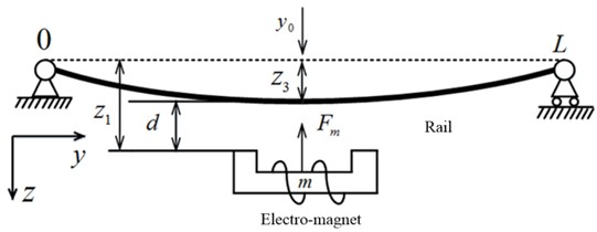
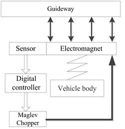
Fig. 1Structural diagram of maglev vehicle-guideway coupling control system

a)
b)
The schematic diagram of the single suspension point-track coupled system is shown as Fig. 1(b). Among them, the origin of coordinate system is located at the “O”, which the intersection of the orbital left bearing and the track. Electromagnets and loads are reduced to an equivalent mass . and are the absolute displacements of electromagnets and guideway, respectively. The air gap is . The mass of unit length and flexural rigidity of the guideway beam are and separately. is the coefficient of viscous damping. is the span of beam. The motion of the maglev guideway can be described by the Bernoulli-Euler beam equation [21-23]:
where is an external force acting on the guideway. It can be approximately expressed as:
According to the vibration theory of continuous beam, it can be found that the vibration of higher modes can occur only when the energy of the excitation is very high [20]. Therefore, the maglev guideway is usually discussed only for the first order mode [21-23]. The problem expressed by the (1) is studied by the modal analysis method. For simple supported beam, the first order modal frequency and the first order modal shape function are as follows [23-24]:
where , according to the theory of mode superposition, flexible guideway model can be expressed as:
where is the amplitude of the first order modal displacement with time. Substituting (4) into (1), both sides of the equation are multiplied by , which has been mentioned earlier. Then the both sides of the equation are integrated from 0 to . Finally, the equation will be got:
where , are the First order modal frequencies and damping ratios separately. Through defining , the both sides of (5) are multiplied by .The equation can be converted:
In addition, the rest of the system state variables can be selected separately. is the vertical change velocity of electromagnet. is the vertical change velocity of the track. is the electromagnet winding current. The model of vehicle track coupling system with the first order vibration mode can be obtained by combining the model of maglev system with flexible guideway:
where:
At present, the double loop PID controller is applied to the most of the low-speed maglev control system. Taking air gap deviation , current , electromagnet velocity three states as feedback control loop [7, 10]. Therefore, it is of practical significance to study the vehicle track coupling dynamics under the maglev control system. Among them, the feedback controller is:
where is the Voltage at equilibrium. is the target air gap. , and are the feedback factor of each loop separately. Substituting (7) into (8), the state equation of the maglev vehicle rail coupling control system can be obtained:
3. Analysis of the hopf bifurcation with double time-delay feedback
When the double delay maglev system is studied, the dynamic equations and electromagnetic equations can be listed according to the symbolic variables, as follows:
An equivalent transformation of (11) can be obtained:
Taking, , as feedback variables, the feedback control parameters are applied to the voltage interface of the electromagnet:
where the position feedback signals and velocity feedback signals with time delay are represented by , respectively.
At the equilibrium point, the value of the state variable is , 0.
Where is the target gap. At this point, the voltage at the equilibrium point is .When the equilibrium point is shifted to the coordinate origin, the linearized system equation can be obtained through the feedback expression:
Furthermore, the characteristic equation of the linear system can be obtained:
where:
Similarly, the expressions about I are brought into orbit equations and expanded by Taylor:
The characteristic equations can be obtain according to (17):
where:
In the analysis of the influence of time delay on the stability of maglev system, they can be divided into 5 cases:
Case (1). 0
By changing the variables, the characteristic equation can be transformed into:
According to the Routh-Hurwitz criterion, if there is no time delay, the maglev system is in stable state if and only if the eigenvalues exist negative real parts.
The existence of time delay can lead to instability of the system. According to past experience, if the real part of characteristic root of characteristic Eq. (16) and (18) is 0, the stability of equilibrium may be changed.
Case (2). 0:
It is easy to find out 0, .When , The equation can be transformed into:
The above equations are derived:
If 0, ( 0), the Eq. (20) has only one positive root. Corresponding to the critical value, the time delay is :
Case (3). :
According to the Hurwitz theorem, satisfies 0 and 0, 0. Because of 0 and 0, there is a positive root . The corresponding critical value of time delay is:
Case (4). 0:
The above equations are derived:
Due to:
There is a positive that satisfies 0 and has a minimum. If:
The Eq. (26) has only one positive root.
The corresponding critical value of time delay is:
Case (5)., 0:
Similarly, when 0, there is a positive root .
The corresponding critical value of time delay is:
The delay critical value above must satisfy the corresponding condition of Hopf bifurcation:
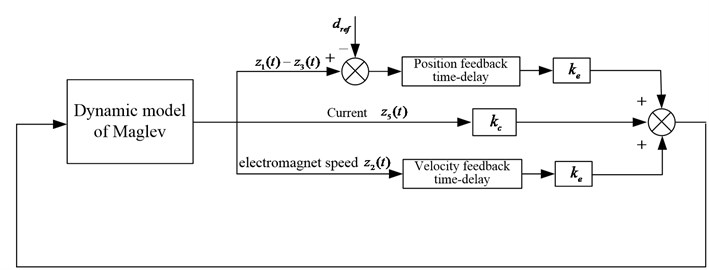
As shown in Fig. 2, the velocity feedback time delay and the displacement feedback delay are taken as the bifurcation parameters for the feedback control of the maglev dynamic model.
Fig. 2the time delay feedback control with block diagram
According to the above inferences, the critical value of the time-delay position feedback loop and the velocity feedback loop under different conditions can be determined. The periodic solutions of Hopf bifurcation and the critical point of the system center manifold can be determined according to the relevant data of the test vehicle at the low speed maglev base of Tongji University and the critical time delay under different conditions. The physical parameters are shown in Table 1.
Table 1Physical parameter values
700 kg | 450 | 4 π×10-7 H·m-1 | 0 |
0.024 m2 | 1.2 | 19.1 A | 0.009 m |
The shadow region represents the stable domain. The stable domain can be verified by numerical calculation. The dynamics of the system outside the region is very complex. Based on the above analysis, bifurcation conditions can be described, as shown in Fig. 3.
Fig. 3Bifurcation diagram in relation to τ1 and τ2
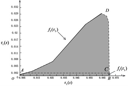
The stability of the stable domain can be improved from the graph. The extension domain of the stable domain is shown in ACDA. In this region, you can choose the appropriate value in to obtain a stability for . According to the solution of the critical delay condition, it is shown that we can obtain the stability of the periodic solution of the Hopf bifurcation at the center manifold of the system at the critical value. The Hopf bifurcation curve (OAD) on the left shows that the Hopf bifurcation is supercritical, and the related limit cycles are stable. The curve on the right (BCD) shows that the Hopf bifurcation is subcritical, and the related limit cycles are unstable. As shown in Fig. 3.
4. Numerical simulations
Through the numerical simulation, many different delay values can be tested to verify the above theoretical results. In addition, we can select four representative delay values near OA, AD, DC and CB to describe the problem.
When 0 s, the critical value of for Hopf bifurcation can be acquired as 0.07 s (the point B from Fig. 3). Two points near the boundary ( 0.065 s and 0.075 s) will be selected to carry out the numerical simulation. The simulation results can be seen in Figs. 4-5.
Fig. 4Simulation results of the maglev system when τ1= 0 s, τ2= 0.065 s
a) Displacement of electromagnet
b) Displacement of rail
c) Airgap
d) Phase locus
We can learn from Fig. 4 that the maglev possesses stability when (in the shaded region). In Fig. 4(a)-(c), it can be seen that the displacement of electromagnet, the displacement of rail and the air gap tend to be stable. In Fig. 4(d), from the limit cycle, it can be seen that the air gap and the air gap change rate gradually approaching 0, which can further explain the system to reach a stable state. In Fig. 5(a), (b), the displacement of electromagnet and the displacement of rail are increasing continuously, which indicates that there is obvious instability phenomenon. In Fig. 5(c), it can be seen that the system loses the stability when (right side of the curve BCD) with the appearance of an emanative vibration. The Fig. 5(d) shows that the limit cycle is unstable. It is known as subcritical Hopf bifurcation when the point is out of the dashed line BCD.
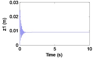
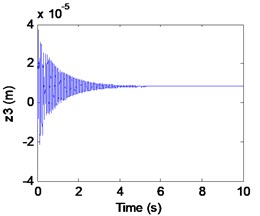
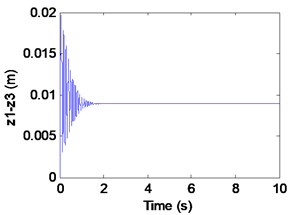
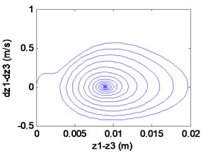
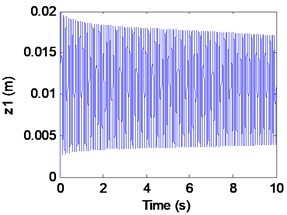
When 0.027 s, the critical value of for Hopf bifurcation can be obtained as 0.0589 s (in the solid line AD). Two points near the boundary ( 0.055 s and 0.063 s) will be selected to carry out the numerical simulations. The simulation results can be seen in Figs. 6-7.
Fig. 5Simulation results of the maglev system when τ1= 0 s, τ1= 0.075 s
a) Displacement of electromagnet
b) Displacement of rail
c) Airgap
d) Phase locus
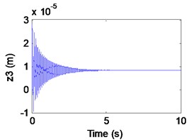
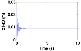
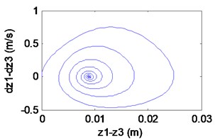
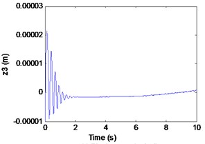
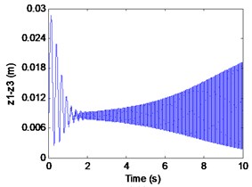
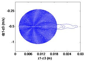
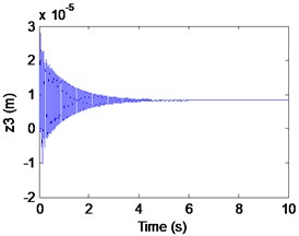
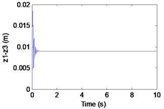
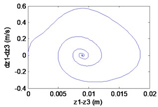
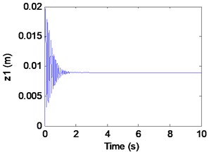
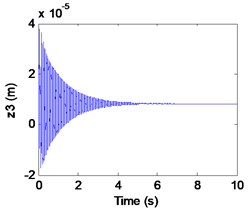
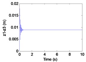
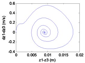
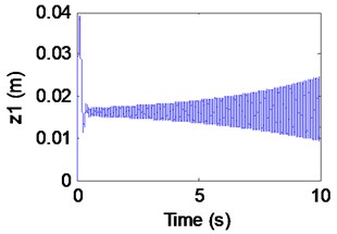
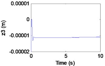
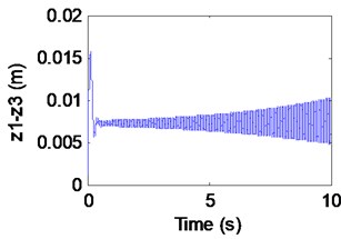
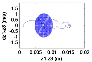
Fig. 6Simulation results of the maglev system when τ1= 0.027 s, τ2= 0.055 s
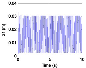
a) Displacement of electromagnet
b) Displacement of rail
c) Airgap
d) Phase locus
We can learn from Fig. 6 that the maglev system is stability when (in the shaded region). It is known as supercritical Hopf bifurcation when the point is out of the solid line AD. In fact, from Fig. 6(a), (b) we can find that the electromagnet the flexible guideway has a stable periodic vibration, which results in the change of airgap and magnetic force. So, the maglev system presents vehicle-coupled-guideway vibration.
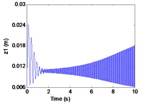
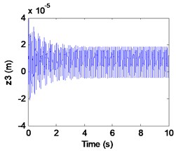
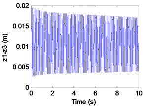
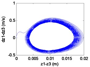
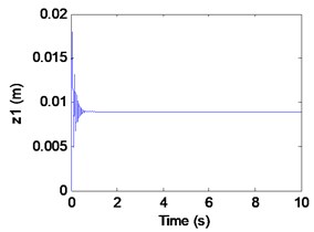
It can be seen from the Fig. 7 that the maglev system loses the stability when (left side of the curve AD) with the appearance of a stable periodic vibration. In Fig. 7(a)-(c), it can be seen that the displacement of electromagnet, the displacement of rail and the air gap tend to be stable. In Fig. 4(d), From the limit cycle, it can be seen that the air gap and the air gap change rate gradually approaching 0, which can further explain the system to reach a stable state.
Fig. 7Simulation results of the maglev system when τ1= 0.027 s, τ2= 0.063 s
a) Displacement of electromagnet
b) Displacement of rail
c) Airgap
d) Phase locus
When 0 s, the critical value of for Hopf bifurcation can be acquired as 0.00133 s (the point A from Fig. 3). Two points near the boundary ( 0.001 s and 0.0016 s) will be selected to carry out the numerical simulation. The simulation results can be seen in Figs. 8-9.
Fig. 8Simulation results of the maglev system when τ1= 0.001 s, τ2= 0 s
a) Displacement of electromagnet
b) Displacement of rail
c) Airgap
d) Phase locus
Fig. 9Simulation results of the maglev system when τ1= 0.0016s, τ2= 0 s
a) Displacement of electromagnet
b) Displacement of rail
c) Airgap
d) Phase locus
We can learn from Fig. 8 that the maglev possesses asymptotic stability when (in the shaded region). In Fig. 8(a)-(c), it can be seen that the displacement of electromagnet, the displacement of rail and the air gap tend to be stable. In Fig. 8(d), From the limit cycle, it can be seen that the air gap and the air gap change rate gradually approaching 0, which can further explain the system to reach a stable state.
In fact, from Fig. 9(a), (b) we can find that the electromagnet the flexible guideway has stable periodic vibrations, which results in the change of airgap and magnetic force. So, the maglev system presents vehicle-coupled-guideway vibration. In Fig. 9(c), it can be seen that the system has a stable periodic vibration when (out of the solid curve AD). The phase portrait of the Fig. 8(d) also illustrates that the limit cycle is unstable. It is known as supercritical Hopf bifurcation when the point is out of the solid line AD.
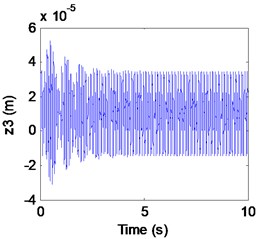
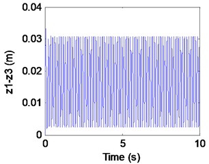
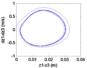
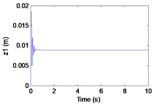
When 0.0675 s, the critical value of for Hopf bifurcation can be acquired as 0.0275 s (in the dashed line BCD). Two points near the boundary ( 0.026 s and 0.03 s) will be selected to carry out the numerical simulation. The simulation results can be seen in Figs. 10-11.
We can learn from Fig.10 that the maglev system is asymptotic stability when (in the shaded region). In Fig. 10(a)-(c), it can be seen that the displacement of electromagnet, the displacement of rail and the air gap tend to be stable. In Fig. 4(d), From the limit cycle, it can be seen that the air gap and the air gap change rate gradually approaching 0, which can further explain the system to reach a stable state.
In Fig. 11(a), (b), the electromagnet displacement and the track displacement are increasing continuously, which indicates that there is obvious instability phenomenon. When (out of the dashed curve BCD) In Fig. 11(c), it can be seen that the system loses the stability with the appearance of an emanative vibration. The phase portrait of the Fig. 11(d) shows that the limit cycle is unstable. It is known as subcritical Hopf bifurcation when the point is out of the dashed line BCD.
Especially, it can be seen that the demand of position feedback time-delay is more rigorous than that of velocity feedback. The value of position feedback time-delay needs to be smaller to keep the system stable. It is also related to the position feedback control which plays a more important regulatory role in the whole controller. Moreover, if the maglev system is stable, should be less than 0.00133 s when 0 s. But if (< 0.07s) increases, which ensures the maglev system stable can increase to almost 0.029 s. It indicates that the stability region is enlarged. It is shown from the simulation results that appropriately adjusting time-delay parameters can change the dynamic response amplitude, which provides a significant method to restrain the vibration.
Fig. 10Simulation results of the maglev system when τ1= 0.026 s, τ2= 0.0675 s
a) Displacement of electromagnet
b) Displacement of rail
c) Airgap
d) Phase locus
Fig. 11Simulation results of the maglev system when τ1= 0.03 s, τ2= 0.0675 s
a) Displacement of electromagnet
b) Displacement of rail
c) Airgap
d) Phase locus
5. Preliminary experimental results
Taking the maglev test train of National Maglev Transportation Engineering R&D center as shown in Fig. 12, the suspension test is implemented on the movable guideway in covered court.
Fig. 12Experimental platform of low speed maglev Center
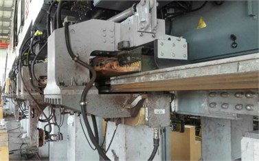
a) Levitation electromagnet
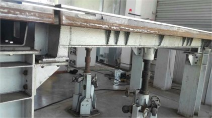
b) Replaceable track
The signal transmission is shown in Fig. 13. In the test maglev vehicle, the maglev train is stably levitated by the interaction between the digital controller and the magnetic suspension chopper. At the same time, the sensor signal with time delay on the magnetic suspension controller acts on the digital controller for real-time feedback [25-28]. The sampling frequency is 2500 Hz, and the experimental parameters of the system and the controller feedback parameters are consistent with the parameters used in the theoretical analysis and simulation. Because of the convenience of the experiment, only a set of time delay parameters is verified here. The time delay in the controller is modified to 0.027 s, 0.055 s and the experiment is carried out. After the train is levitated, data sampling is carried out. Finally, the collected signal is processed by Kalman filter [29-31]. The experimental results obtained are shown in Figs. 14-16.
Fig. 13Signal transmission in test maglev vehicle
a)
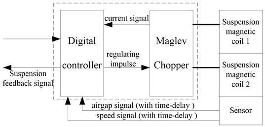
b)
Fig. 14Experimental results: suspension air gap response
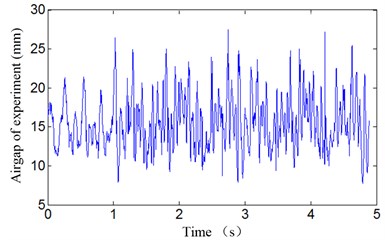
Fig. 15Experimental results: electromagnetic acceleration response
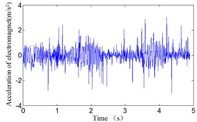
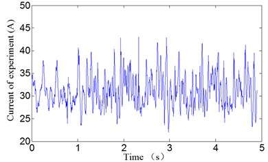
In the previous section, the numerical simulation of vehicle track coupling vibration with double time-delay (velocity and position signal feedback time-delays) based on flexible track is carried out in numerical simulation. By simulating different time delay values, the theoretical method can be verified, and some signals and parameters can be used for subsequent experiments. In the process of experiment, the time delay values of the simulation analysis, which can lead to coupling vibration, is taken to prove that the theoretical method is effective. The output of three state variables of air gap, electromagnet acceleration and current can be obtained according to the experiment.
It can be seen that the vehicle-guideway coupling vibration occurs when 0.027 s, 0.055 s. The coupling vibration is stable periodic vibration and the amplitude of the air gap vibration is about 20 mm, which are close to the simulation results. Considering the complexity of the actual system model and the presence of disturbances in the experiment, it can be concluded that the proposed theoretical analysis method and simulation results are believable.
Fig. 16Experimental results: current response
6. Conclusions
The vibration phenomenon is abundant when the Maglev train is levitated on the flexible guideway. The study of the vibration problem is very important to learn the complicated dynamic behavior of Maglev system and improve the ride quality of the train. In this paper, we investigate the Hopf bifurcation of Maglev train running on flexible guideway with time delays of position and velocity feedback control. Importance is given to both the delays, then the sufficient conditions for stability of the equilibrium point and the existence of Hopf bifurcation when 0, 0, 0, 0, 0, 0 are obtained. The possibility of the interaction between the two delays is proved. The two parameter bifurcation diagram describes the combined effects of discrete time delay and on the dynamic characteristics of Maglev train. The theoretical solution is verified by numerical simulation. If Maglev train has stability, when 0, should not exceed . And if can increase in a certain range, the value of which can stabilize the system will also increase. that is, the stability region is extended. Vice versa. Extensive numerical simulation and experiment results are included to verify theoretical analysis. It is indicated that the complicated dynamic behavior of Maglev train can be changed by the double tome-delays. And the stability domain with and drawn in this paper is especially valuable for guiding to adjust time-delayed parameters to suppress the dynamic response and vibration between Maglev train and guideway. The vibration of Maglev train is very serious. In practical application, the adjustment of time delay parameters plays a guiding role in avoiding vibration. The study of vibration is of great significance to the stable operation of Maglev train.
References
-
Zhou D. F., Hansen C. H., Li J., et al. Review of coupled vibration problems in EMS Maglev vehicles. International Journal of Acoustics and Vibrations, Vol. 15, Issue 1, 2010, p. 10-23.
-
Li J. H., Li J., Zhou D. F., Yu P. C. Self-excited vibration problems of Maglev vehicle-bridge interaction system. Journal of Central South University, Vol. 21, Issue 11, 2014, p. 4184-4192.
-
Li J., Deng G., Luo C., et al. A hybrid path planning method in unmanned air/ground vehicle (UAV/UGV) cooperative systems. IEEE Transactions on Vehicular Technology, Vol. 65, Issue 12, 2016, p. 9585-9596.
-
Wang H., Shen G., Li L., et al. Study on the Maglev vehicle-guideway coupling vibration system. Proceedings of the Institution of Mechanical Engineers, Part F: Journal of Rail and Rapid Transit, Vol. 229, Issue 5, 2015, p. 741-750.
-
Shi X. H., She L. H., Chang W. S. The bifurcation analysis of the EMS Maglev vehicle-coupled-guideway system. Acta Mechanica Sinica, Vol. 36, Issue 5, 2004, p. 634-640.
-
Wang H. Applying Hopf Bifurcation Theory to Research the Vehicle-Guideway-Coupled Elastic Vibration Control of Maglev Train. National University of Defense Technology, 2008.
-
Zhang L. L. Research on Hopf Bifurcation and Sliding Mode Control for Suspension System of Maglev Train. Hunan University, 2010.
-
Wu J. J., Shen F., Shi X. H. Stability and Hopf bifurcation of the Maglev system. Journal of Vibration and Shock, Vol. 29, Issue 3, 2010, p. 193-196.
-
Lee J. S., Kwon S. D., Kim M. Y., et al. A parametric study on the dynamics of urban transit Maglev vehicle running on flexible guideway bridges. Journal of Sound and Vibration, Vol. 328, Issue 3, 2009, p. 301-317.
-
Li J., Yu F. R., Deng G., et al. Industrial Internet: A survey on the enabling technologies, applications, and challenges. IEEE Communications Surveys and Tutorials, Vol. 19, Issue 3, 2017, p. 1504-1526.
-
Shi X. H., Long Z. Q. Nonlinear vibration analysis of the Maglev guideway-vehicle coupling control system. Journal of the China Railway Society, Vol. 31, Issue 4, 2009, p. 38-42.
-
Hassard B. D., Kazarinoff N. D., Wan Y. H. Theory and Applications of Hopf Bifurcation. Cambridge University Press, 1981.
-
Zhang Z., Zhang L. Hopf bifurcation of time-delayed feedback control for Maglev system with flexible guideway. Applied Mathematics and Computation, Vol. 219, Issue 11, 2013, p. 6106-6112.
-
Hongpo Wang J. L., Zhang K. Non-resonant response, bifurcation and oscillation suppression of a non-autonomous system with delayed position feedback control. Nonlinear Dynamics, Vol. 51, Issue 3, 2008, p. 447-464.
-
Zhang L., Huang L., Zhang Z. Hopf bifurcation of the Maglev time-delay feedback system via pseudo-oscillator analysis. Mathematical and Computer Modelling, Vol. 52, Issues 5-6, 2010, p. 667-673.
-
Qiang H. Y., Li W. L., Sun Y. G., Liu X. Y. Levitation chassis dynamic analysis and robust position control for Maglev vehicles under nonlinear periodic disturbance. Journal of Vibroengineering, Vol. 19, Issue 2, 2017, p. 1273-1286.
-
Xing S., Jiang T. Research on realization of force feedback of vehicle remote control station steering simulation system. Journal of Measurements in Engineering, Vol. 5, Issue 2, 2017, p. 100-105.
-
Wang H., Zhong X., Shen G. Analysis and experimental study on the MAGLEV vehicle-guideway interaction based on the full-state feedback theory. Journal of Vibration and Control, Vol. 21, Issue 2, 2013, p. 51-74.
-
Sun Y. G., Qiang H. Y., Mei X., et al. Modified repetitive learning control with unidirectional control input for uncertain nonlinear systems. Neural Computing and Applications, 2017, https://doi.org/10.1007/s00521-017-2983-y.
-
Cui K., Qin X. Virtual reality research of the dynamic characteristics of soft soil under metro vibration loads based on BP neural networks. Neural Computing and Applications, 2017, p. 1-10, https://doi.org/10.1007/s00521-017-2853-7.
-
Kong E., Song J. S., Kang B. B., et al. Dynamic response and robust control of coupled Maglev vehicle and guideway system. Journal of Sound and Vibration, Vol. 330, Issue 25, 2011, p. 6237-6253.
-
Yau J. D. Vibration control of Maglev vehicles traveling over a flexible guideway. Journal of Sound and Vibration, Vol. 321, Issues 1-2, 2009, p. 184-200.
-
Li J., Li J., Zhou D., et al. The active control of Maglev stationary self-excited vibration with a virtual energy harvester. IEEE Transactions on Industrial Electronics, Vol. 62, Issue 5, 2015, p. 2942-2951.
-
Sun Y. G., Qiang H. Y., Chang D. F., Wang R. Response characteristic analysis of nonlinear vortex-induced vibration of tension leg platform in deep sea. Journal of the Balkan Tribological Association, Vol. 22, Issue 3, 2016, p. 2518-2534.
-
Li J. Q., He S. Q., Ming Z. An intelligent wireless sensor networks system with multiple serves communication. International Journal of Distributed Sensor Networks, Vol. 7, 2015, p. 1-9.
-
Wei W., Song H., Li W., et al. Gradient-driven parking navigation using a continuous information potential field based on wireless sensor network. Information Sciences, Vol. 408, 2017, p. 100-114.
-
Xiao P., Wu J. S., Cowan C. F. N. MIMO detection schemes with interference and noise estimation enhancement. IEEE Transactions on Communications, Vol. 59, Issue 1, 2011, p. 26-32.
-
Du J., Xiao P., Wu J., et al. Design of isotropic orthogonal transform algorithm-based multicarrier systems with blind channel estimation. IET Communications, Vol. 6, Issue 16, 2012, p. 2695-2704.
-
Cui K., Zhao T. T. Unsaturated dynamic constitutive model under cyclic loading. Cluster Computing, 2017, p. 1-11, https://doi.org/10.1007/s10586-017-0881-9.
-
Yang A., Han Y., Pan Y., et al. Optimum surface roughness prediction for titanium alloy by adopting response surface methodology. Results in Physics, Vol. 7, 2017, p. 1046-1050.
-
Ding G., Tan Z. Indoor fingerprinting localization and tracking system using particle swarm optimization and Kalman filter. IEICE Transactions on Communications, Vol. 98, Issue 3, 2015, p. 502-514.
Cited by
About this article

The authors thank the National Key R&D Program of China “Research on Key Technologies of Maglev Transportation System” (2016YFB1200600) and the Hunan Science and Technology Special Project of Hunan Province “Low Speed Maglev Train Complete Engineering Technology and High Reliable Operation Demonstration” (2015GK1001).
