Abstract
In order to study the relationship between an underwater shock wave and jet thrust oscillation, a simulation model of underwater jet is established. As per a numerical calculation based on the SST (Shear Stress Transport), and VOF (Volume of Fluid) models, the flow speed of jet gas has been changed with the pressure ratio. When the jet speed becomes supersonic, its corresponding shock structure will occur. When the pressure ratio is small, the shock wave structure in the nozzle is normal, and in case of an increase of the jet speed, the jet is moving from the nozzle inside to the outside. When the pressure ratio reaches a certain number, the shock is out of nozzle, and the nozzle is operating in an over-expansion state, the thrust oscillation amplitude is high. When the pressure ratio is large, and the nozzle is operating in the under-expanded state, then the structure of shock wave is very complex, jet back-attack no longer appears, and the thrust amplitude is rather smaller than the over-expanded one. Two kinds of situations are compared. And the comparison revealed that the highly under-expanded state is more conducive to the stability of the underwater vehicle, which can provide a reference for the corresponding design.
1. Introduction
The underwater operating process of a rocket motor is a typical two-phase flow problem [1-4]. Wang Boyi [5] et al. studied the dynamic behavior of an underwater supersonic gas jet by experiment. Through the flow visualization, it reveals the phenomenon of evolution from a probe for the jet near-zone fluctuating pressure distribution. Shi Honghui [6] et al. recorded the real-time state of underwater supersonic gas jet with a high-speed camera. It demonstrated the jet gas in aggregate basin evolution process clearly. The exhaust underwater noise was investigated experimentally and theoretically by Pueyo L. [7]. Tang Jianing [8] gaseous jets injected into water are typically found in underwater propulsion, and the flow is essentially unsteady and turbulent. AMP Thomas [9] found a new synthetic jet actuation concept for small, low speed, highly maneuverable AUVs. S. G. Shereena [10] worked out the drag reduction of axisymmetric underwater bodies by air jet injection into the boundary layer. He Miaosheng [11] made directed measurements of the interfacial behavior of water-submerged gas jets, with a nozzle operated in over-expansion to highly under-expansion conditions, using the high-speed digital photography method. E. Loth [12] conducted the structure and mixing properties of an experimental and numerical investigation of the structure of plane underexposed turbulent air jets in water. GN Oryall [13] measured the gas fraction and bubble frequency distributions in a submerged air jet, injected horizontally into mercury with different ranging of nozzle diameters and Froude numbers. He [14] found out the deformation of a free surface between two fluids in a gravitational field, due to a jet in the lighter fluid impinging at right angles to the surface. Loth and Faeth [15] found that there was an external expansion to the gas jet near-zone, and for this matter, the experimental verification was made. Surin V. A. [16] experimentally demonstrated that the fluctuation mechanism of the underwater gas jet was related to the jet intensity in the center area. Dai T. [17] focused on a comparison between the optimum-expansion and over-expansion, and the results showed that the high speed gas jet in the static water could induce the pressure pulse upstream the nozzle outlet. The complex shock structure in the process of the jet flow causes a strong hydrodynamic pressure. Ozawa Y. [18] found that there was a complex shock wave system in the core area of the air flow, and the specific shock structure depended on the Mach number at the nozzle outlet, nozzle outlet pressure and back pressure ratio.
Because of the solid rocket operating in water is not at a fixed depth, it is used to be launched from deep water to attack targets on the water surface. Therefore, the operating rocket state must consist in the transition from over-expansion to under-expansion. However, the comparative analysis of two underwater states is very different from that in air, especially in terms of the shock wave structure and thrust characteristics. So, the aim of this paper is to analyze the flow structure and thrust oscillation in the over-expanded condition. By comparing with different operating conditions, it reveals the underlying mechanisms of jets flow and thrust characteristics. These results are useful in the design and engineering application of submerged motor.
2. Concept and theories
2.1. Governing equations
The high-temperature and high-pressure gas is regarded as the control fluid. Hence, the governing equations based on the VOF model involving the mass conservation equation, momentum conservation equation, energy conservation equation and volume transfer equation are presented as follows [19]:
where, is a physical property of the mixture, , the volumes of the phases satisfy 1.
The density of two phases is as follows:
The Froude number in the gaseous jets is (103). The body force in the momentum conservation equation cannot be neglected. The energy is as follows:
2.2. Nozzle design
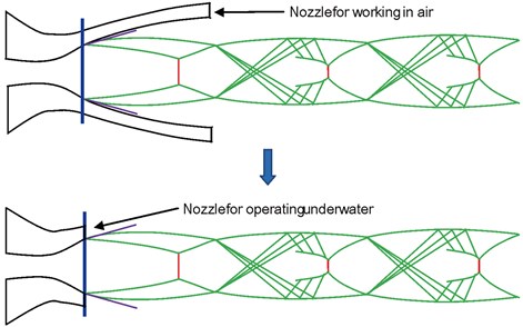
The nozzle operating in air but used under water will have the separation phenomenon between air and water because the back-pressure in water is rather larger than that in air. Thrust for air-water separation phenomenon will increase unstable factors for nozzle running under water [20]. The expansion ratio of nozzle operating under water is different from air, and it will be far less than that in air, as shown in Fig. 1. According to the design conditions, it would be better if all the shock waves go outside the nozzle. Therefore, the structure of nozzle should be designed as shown in Fig. 1(b).
Fig. 1Nozzle design for underwater operation
2.3. Turbulence model and validation
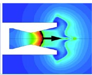
The nozzle flow contains rich combinations of flow interactions and flow physics. As irreversible phenomena like shocks and/or flow separation may occur inside the nozzle, the supersonic jet flow is featured with a very complex structure [21]. In Fig. 2, the validation of RANS (Reynolds-averaged Navier-Stokes) turbulence models is conducted for the optimal analysis of supersonic converging-diverging nozzle through the comparison of computational results with experimental data. The result of three stimulation models of S-A (Spalart-Allmaras), RNG (Renormalization Group) -, and - SST was compared with experimental data. It can show that they have the same structure of a shock wave, but the shock wave position is different, and the SST model is much closer to the experimental results than the other models. Therefore, the SST is more suitable for the jet shock problems.
Fig. 2Comparison of computational shock structure with experimental results at NPR = 2.412 [9]
![Comparison of computational shock structure with experimental results at NPR = 2.412 [9]](https://static-01.extrica.com/articles/17657/17657-img2.jpg)
2.4. Jet regions
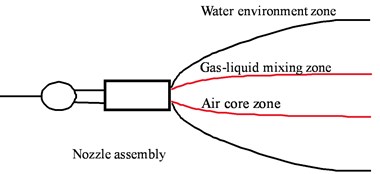
Fig. 3 shows underwater jet regions. In the Figure, starting from the jet axis center outward, it has been divided into three regions [22]:
(1) Air core zone. Close to the center of a jet area, the priority is given to gas; liquid exists in the form of particles, so it is called as a particle layer.
(2) Gas-liquid mixing zone. Close to the water environment on the area side, the priority is given to water; gas exists in the form of bubbles, so it is referred to as a bubble sheet.
(3) Water environment zone. There is a complex shock wave system in the air core zone. The specific shock wave structure depends on the gas nozzle outlet, Mach number and ratio of nozzle outlet pressure and back pressure.
Fig. 3Underwater jet regions
2.5. Critical pressure
In Ref. [23], the change trend of nozzle outlet pressure is consistent with the back-pressure. The reason is that there is a critical pressure for each nozzle, and it is defined as:
where, is the velocity ratio at the nozzle outlet.
There is the following law according to the change [23]:
(1) The back-pressure of nozzle is upper than , the shock wave moves inside the nozzle, and the pressure pulsation is created. The nozzle outlet pressure is determined by the back-pressure.
(2) The back-pressure of nozzle is lower than , the shock wave moves outside the nozzle, and the pressure pulsation is gone. The nozzle outlet pressure is determined by design conditions.
(3) The back-pressure of nozzle is far lower than , the shock wave moves far away from the nozzle. The back-pressure is unable to reach the wall.
2.6. Shock wave structure
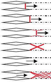
Fig. 4 shows the relationship between the shock wave and flow state [24]. In the Fig. 4, with the increase of flow velocity, the shock wave from the nozzle inside goes into outside, and the structure of the normal shock wave begins being oblique, and is eventually developed into a very complicated form.
Fig. 4Jet shock wave structure
a)
b)
3. Model for calculation
3.1. Structure and grid
Because the axisymmetric model is simple, reliable, and its creation spends less time, it is easy to find out the laws of Physics, and it can be a good solution of the underwater jet problem, which has been verified by a large number of experiments. Therefore, an axisymmetric two-dimensional model is used here. To overcome the influence of the boundary conditions on the main flow into the jet cross-sectional area, the total length of the 2-d computational domain of the model is 500 times the nozzle inlet diameter, and the width is 330 times the diameter of the nozzle outlet. The grid of the horizontal jet is shown in Fig. 5, where the mesh refinement is applied to the wall, throat, and core of jets. The boundary in four horizontal directions is the wall while the pressure outlet forms the upper and lower boundaries, as the pressure inlet does in the engine intake. A computational mesh is generated by mapping a structured mesh with 1.558.400 cells. Ideal air is used as a high-pressure gas, and the water is regarded as incompressible. The Prandtl number of gas is 0.712, and that of water is 5.43. The thermal conductivities of gas and water are 0.025 W/m·K and 0.6 W/m·K respectively. The specific heat of the gas is 1.4. The time step used during computation is 10-8 s.
Fig. 5Underwater jet stimulation model
3.2. Boundary and initial condition
The total pressure of a free outlet boundary is the ambient pressure, which is calculated according to the water depth, and the temperature is 300 K. The field wall boundary is under a stationary wall condition, and no-slip and adiabatic rules pertain. The whole flow field is symmetrical. The initial condition of the nozzle is gaseous while the outer field is water. These two parts are relatively static. The total pressure at the nozzle inlet is the initial pressure of the combustion chamber . The initial water pressure is that of the water depth considered as , where is the water depth, is the atmospheric pressure (0.101 MPa). Upon starting the calculation, these two fields are interconnected immediately. In this paper, the governing equations are discredited using the finite volume method, and the SIMPLE scheme is utilized. Considering the difficulty in ensuring the accuracy of gas-liquid two-phase simulation, the two-order upwind scheme is used for interpolation.
The model used in the paper is the same with Ref. [6]. In the reference, models with three densities are used to verify the grid independence. It shows that the number of grids has no effect on the results in the paper.
4. Results and analysis
Fig. 6 shows a shock wave of an underwater supersonic jet, which is located inside the nozzle [25]. In the Fig. 6, form to , there is a normal shock wave inside the nozzle, and it has reciprocating motion. When time is , the back-pressure is too large to be the shock wave, and the flow velocity changes from supersonic to undersonic. When the normal shock wave is near the nozzle, it will convert to reciprocal motion around the nozzle outlet, and the thrust oscillation is very unstable. In Ref. [25], the relationship between back-pressure and outlet-pressure is explained in detail.
Fig. 6Normal shock wave inside nozzle
a)
b)
c)
d)
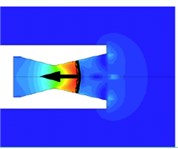
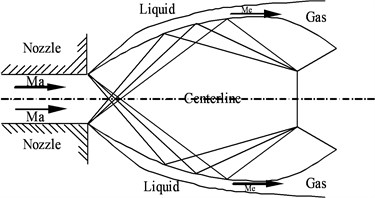
Fig. 7(a) shows a conceptual sketch of an underwater supersonic jet, which works in the over-expanded status. A shock-cell structure and gas/liquid boundary co-exist in the flow field [26, 27]. Obviously, this kind of flow field usually cannot be stable. In the Figure, Ma means the design Mach number, and Me means the jet Mach number behind the incident inclined shock wave.
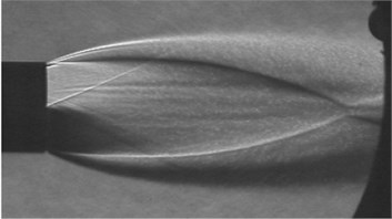
Fig. 7(b) shows a shock-cell structure of the jet in air operating in the over-expanded status. Obviously, this kind of shock-cell structure usually is very similar to the conceptual sketch of an underwater supersonic jet in the over-expanded condition, and the flow field is unstable too, however, it is operating in air, whose feedback pressure in the nozzle is small. So, this kind of shock-cell structure also has a little influence on the thrust in air [22].
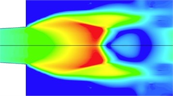
Fig. 7(c) shows a typical result of shock-cell structure of an underwater supersonic air jet in simulation conditions (the combustion chamber pressure is 3 MPa; the water depth is 50 m). Obviously, the shock-cell structure is also similar to Fig. 1 and 2. So, an underwater shock wave is similar to a shock wave in air because they are in the same status. Due to that the back-pressure is greater than the underwater pressure, the underwater flow field is more unstable than the air jet, and the underwater jet changes the shock wave structure with time.
Fig. 8 shows a typical result of a thrust measurement of an underwater supersonic air jet in simulation conditions (the combustion chamber pressure is 3 MPa; the water depth is 50 m). In Ref. [28], there is a thought that the thrust oscillation is relevant to the pressure of nozzle wall. In Ref. [6], the “back-attack” or jet expansion feedback is caused by a change of shock-cell. So, the thrust oscillation is relevant to a change of shock-cell in essence.
In Ref. [29], there is a thought that the pressure signals are composed of (1) high amplitude and low frequency pressures caused by the “back-attack” or jet expansion feedback; (2) medium amplitude and medium frequency pressures; (3) low amplitude and high frequency pressures caused by the jet turbulence. It is highlighted in this paper that the jet bulge is responsible for the second part of the pressure oscillation. It is in accordance with thrust oscillations in Fig. 2. So, the simulation results of this paper are accurate.
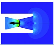
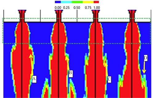
Fig. 9(a) shows a conceptual sketch of an underwater supersonic jet, which works in the highly under-expanded status. A shock-cell structure and gas/liquid boundary co-exist in the flow field [26, 27]. Obviously, this kind of flow field is usually more stable than the over-expanded status. In the Fig. 9, and mean the same as shown in Fig. 1.
Fig. 9(b) shows a shock-cell structure of the air jet operating in the under-expanded status. Obviously, this kind of shock-cell structure usually is also very similar to the conceptual sketch of an underwater supersonic jet in the under-expanded status [23].
Fig. 9(c) shows a typical result of shock-cell structure of an underwater supersonic air jet in simulation conditions (the combustion chamber pressure is 12 MPa; the water depth is 50 m). Obviously, the shock-cell structure is also similar to Fig. 1 and 2. So, the underwater shock wave is also similar to the shock wave in air, which they are in the same status. However, as compared with the over-expanded status, the flow filed is very unstable.
Fig. 10 shows a typical result of a thrust measurement of an underwater supersonic air jet in simulation conditions (the combustion chamber pressure is 12 MPa; the water depth is 50 m). In the Figure, the thrust oscillation amplitude is rather smaller than that shown in Fig. 7. It is due to that the expansion shock has blocked the movement of gas going to the nozzle wall. So, the flow filed has little changes, and the thrust oscillation amplitude is small. As compared to the oscillation amplitude of thrust between the ones shown in Fig. 8 and in Fig. 10, the nozzle running in the under-expanded status is more unstable than that in the over-expanded one.
Fig. 7Conceptual sketch of underwater supersonic gas jet in over-expanded status. Ma is the design Mach number. Me is the jet Mach number behind the incident inclined shock wave
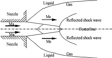
a) Shock wave theory model
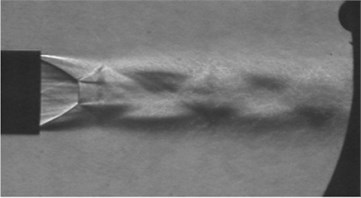
b) Experimental results in air
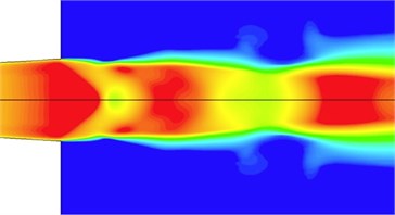
c) Simulation results underwater
Fig. 8Thrust measurement of shock wave feedback of underwater over-expanded air jet at nozzle wall. The nozzle throat and outlet diameters are 16 and 20 mm, respectively
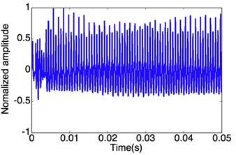
Fig. 11 shows the underwater jet structure. Due to that the back-pressure of water environment is not very large relative to the nozzle outlet pressure, there is a necking before the low pressure area of shock wave, the supersonic airflow velocity decreases, the pressure begins to rise, and shock wave surface moves back. With increasing the pressure, the necking section pressure becomes higher than the environmental one, the jet area is increased, and the supersonic jet begins to be accelerated again. In this case, the gas pressure is reduced, the shock wave surface is moved outside the pipe, so on, the shock wave surface just makes a slight oscillation near the nozzle, the jet shape is relatively stable.
Fig. 12 shows the structure of an underwater supersonic gas jet in the under-expanded status. In the Figure, the boundary of highly under-expansion is a line, and there is no corresponding fracture and back-attack phenomenon in the jet structure. The jet outlet nozzle is rapidly expanding, and the neck position is far from the nozzle. The angle of A, B, C, and D is the same.
Fig. 9Conceptual sketch of underwater supersonic gas jet. Ma is the design Mach number. Ma is the jet Mach number behind the incident inclined shock wave
a) Shock wave theory model
b) Experimental results in air
c) Simulation results underwater
Fig. 10Thrust measurement of shock wave feedback of underwater over-expanded air jet at the nozzle wall. The nozzle throat and outlet diameters are 16 and 20 mm, respectively
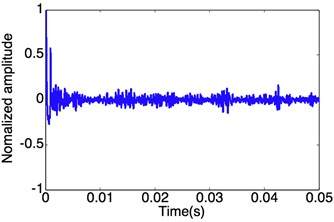
Fig. 11Conceptual sketch of underwater supersonic gas jet in over-expanded status. Ma is the design Mach number. Me is the jet Mach number behind the incident inclined shock wave
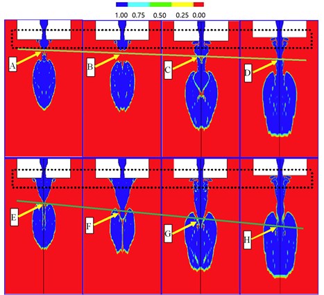
Fig. 12Structure of underwater supersonic gas jet in under-expanded status
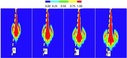
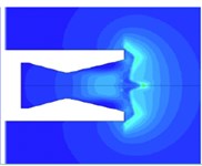
Fig. 13 is a partial view of Fig. 11 field near the jet nozzle. It is indicated by the Fig. 13 that the jet structure in the vicinity of the nozzle is almost constant, and the effect of the jet gas at the outlet, and the nozzle wall surface is small, so the jet height is relatively stable. In the Fig. 13, A, B, C, and D are far away from the nozzle.
Fig. 13Structure of underwater supersonic gas jet over-expanded in par
5. Conclusions
By comparing and analyzing the simulation results, it is found that the structure of underwater gas jet has a certain relationship with the shock wave:
1) the underwater jet shock wave is similar to the shock wave in air.
2) when the nozzle works in the expansion state, there are the back-attack and other typical processes in the jet flow, and the jet oscillation amplitude is larger.
3) when the nozzle works in a highly under-expanded state, there are not the back-attack and other typical processes in the jet flow, and the jet oscillation amplitude is smaller.
The reason for such results is that the operating state is different from the jet condition, and the shock wave structure is also different. When it is in the highly under-expanded status, the jet air flows out of the nozzle with a rapid expansion, and it is far away from the necking position to the nozzle outlet, and gas return cannot reach the back wall, thus the influence of thrust oscillation is weakened.
References
-
Xu Xiaoqiang Research on High-Speed Jet of Underwater Gas. Zhejiang University, 2004, (in Chinese).
-
Neto I. E., Zhu D. Z., Rajaratnam N. Bubbly jets in stagnant water. International Journal of Multiphase Flow, Vol. 34, 2008, p. 1130-1141.
-
Gulawani S. S., Dahikar S. K., Joshi J. B., et al. CFD simulation of flow pattern and plume dimensions in submerged condensation and reactive gas jet into liquid bath. Chemical Engineering Science, Vol. 63, 2008, p. 2420-2435.
-
Ozawa Y., Mori K. Characteristics of jetting observed in gas injection into liquid. Transactions ISIJ, Vol. 23, 1983, p. 764-768.
-
Wang Boyi Dai Zhenqing Qi Longxi Shi Honghui Experimental study on back-attack phenomenon in underwater supersonic gas jets. Chinese Journal of Theoretical and Applied Mechanics, Vol. 39, Issue 2, 2007, p. 267-272.
-
Shi H. H., Wang B. Y., Dai Z. Q. Research on the mechanics of underwater supersonic gas jets. Science China Physics, Mechanics and Astronomy, Vol. 53, Issue 3, 2010, p. 527-535.
-
Pueyo L., Bermejo M., Richardson J. W. Systematic interpretation of experimentally measured and theoretically calculated spectra of transition-metal compounds by optimized, linearized crystal field fitting procedure. Journal of Solid State Chemistry, Vol. 31, Issue 2, 1980, p. 217-226.
-
Jia Ning, Tang, Ning Fei, et al. Flow structures of gaseous jets injected into water for underwater propulsion. Acta Mechanica Sinica, Vol. 27, Issue 4, 2011, p. 461-472.
-
Thomas A. M. P., Milano M., Sell M. G. G., et al. Synthetic jet propulsion for small underwater vehicles. IEEE International Conference on Robotics and Automation, 2005.
-
Shereena S. G., Vengadesan S., Idichandy V. G., et al. CFD study of drag reduction in axisymmetric underwater vehicles using air jets. Engineering Applications of Computational Fluid Mechanics, Vol. 7, Issue 2, 2013, p. 193-209.
-
He M., Qin L., Liu Y. Oscillation flow induced by underwater supersonic gas jets from rectangular Laval nozzle. Procedia Engineering, Vol. 99, 2015, p. 1531-1542.
-
Loth E., Faeth G. M. Structure of plane under-expanded air jets into water. Aiche Journal, Vol. 36, Issue 6, 1990, p. 818-826.
-
Oryall G. N., Brimacombe J. K. Physical behavior of gas jet injected horizontally into liquid metal. Metallurgical and Materials Transactions B, Vol. 7, Issue 3, 1976, p. 391-403.
-
He A., Belmonte A. Deformation of liquid surface due to impinging gas jet: conformal mapping approach. Physics of Fluids, Vol. 22, Issue 4, 2010, p. 557-563.
-
Loth E., Faeth G. M. Structure of under-expanded round air jets submerged in water. International Journal of Multiphase Flow, Vol. 15, Issue 4, 1989, p. 589-603.
-
Surin V. A., Yevchenko V. N., Rubin V. M. Propagation of Gas Jet in Liquid. USSR, Physics and Mathematics, 1984.
-
Dai T., Wiegert R. G. Field study of photosynthetic capacity and its response to nitrogen fertilization in spartina alterniflora. Estuarine Coastal and Shelf Science, Vol. 45, Issue 2, 1997, p. 273-283.
-
Ozawa Y., Smith D., Craige E. Origin of third heart sound. II. Studies in human subjects. Circulation, Vol. 67, Issue 2, 1983, p. 399-404.
-
Gan X. S., Jia Y. J., Lu C. J., Cao J. Y. Research on numerical simulation of combustion gas jet under water. Journal of Solid Rocket Technology, Vol. 32, 2009, p. 23.
-
Hyun Ah Choi, Ho Dong Kam, Jeong Soo Kim Numerical investigation on the correlation between shock structure and thrust performance in over-expanded nozzle. 29th Congress of the International Council of the Aeronautical Sciences, Russia, 2014.
-
Kam H. D., Kim J. S. Assessment and validation of turbulence models for the optimal computation of supersonic nozzle flow. Korean Society of Propulsion Engineers, Vol. 17, Issue 1, 2013, p. 18-25.
-
Tang Jianing Study on the Characteristics of Underwater Solid Rocket Engines. Beijing, Institute of Technology, Beijing, 2012.
-
Zapryagaev V. I., Kudryavtsev A. N., Lokotko A. V., et al. Experimental and numerical study of supersonic-jet shock-wave. Structure, Vol. 20, Issue 85, 2002, p. 6250-6253.
-
Dong Shiyan, Zhang Zhaoliang Principle of Solid Rocket Motor. Beijing Institute of Technology press, Beijing, 1996.
-
Anderson J. D. Fundamentals of Aerodynamics. McGraw Hill, 1991.
-
Dai Z. Q., Wang B. Y., Qi L. X., Shi H. H. Experimental study on hydrodynamic behavior of high-speed gas jet in still water. Acta Mechanica Sinica, Vol. 22, 2006, p. 443-448.
-
Wang B. Y., Dai Z. Q., Qi L. X., Shi H. H. Experimental study on back-attack phenomenon in underwater supersonic jets. Journal of Theoretical and Applied Mechanics, Vol. 39, Issue 2, 2007, p. 267-272, (in Chinese).
-
Wang X. G., Wang C., Guo, Shi H. H. Study on vibrating flow type of submerged high-speed gas jets in two-dimensional water tank. Journal of Zhejiang Sci-Tech University, Vol. 26, Issue 4, 2009, p. 613-618, (in Chinese).
-
Shi H. H., Guo Q., Wang C. Oscillation flow induced by underwater supersonic gas jets. Shock Waves, Vol. 20, Issue 4, 2010, p. 347-352.
Cited by
About this article

