Abstract
With respect to the calibration of dynamic pressure measurement system under specific underwater explosion application environment, this paper has proposed an experimental calculation method for the dynamic characteristics of underwater shock water pressure sensor based on a preloaded water shock tube. This was done by analyzing the dynamic calibration principles of the preloaded water shock tube and studying the dynamic influencing factors pertaining to the sensor. Moreover, a dynamic calibration experiment for the sensor was also designed based on a comparative calibration method, through which a calculation method for the dynamic characteristics of underwater shock wave pressure sensor was acquired. The experimental results have proven that applying preloaded water shock tube can effectively acquire the dynamic characteristics of the pressure sensor, thereby providing a research framework for the dynamic calibration of underwater explosion shock wave pressure sensor.
1. Introduction
The underwater shock wave is one of the main forms of underwater explosion. According to a large number of experimental data, shock wave energy in preliminary test of underwater explosion is about a half of the total energy of underwater explosion [1]. Research on underwater explosion is mainly predicated on military purposes and hence analyzing the dynamic characteristics of underwater shock wave pressure sensor is significant [2, 3]. The shock wave signals of underwater explosion are related to water depth. Dong et al [4] verified influences of underwater explosion depth on bubble pulsation of shallow water explosion, and Ghoshal and Mitra [5] verified that underwater explosion depth played an important role in determining the basis for reflection coefficient. Therefore, it is necessary to simulate and control the water depth in experiment. The shock wave of underwater explosion is a signal of high-frequency instantaneous variation, which makes it necessary to analyze its dynamic characteristics. At present, many dynamic experiments for underwater shock wave pressure are conducted in underwater explosion containers [6] that are huge and expensive. Besides, the standard grain explosion method is normally applied, from which errors of measurements acquired are large [7]. Zhu and Wen [8] proposed a water shock tube for high-pressure dynamic calibration which greatly shortened the volume of previous containers for underwater explosion and reduced its operating cost. Gong and Li [9] further proposed a dynamic calibration method for preloaded water shock tubes. This method uses the basis of the Quasi pulse calibration theory [10,12] to analyze the dynamic characteristics of pressure sensor, and processed shock wave signals in the water shock tube as signal, instead of applying the standard pressure sensor, to consider the signal measured by calibrated pressure sensor as impulse response and directly calculate dynamic characteristics of calibrated sensor, hence resulting in large error. Therefore, it is necessary to study a more accurate experimental method for the dynamic characteristics of underwater shock wave pressure sensor.
This paper used a self-developed preloaded water shock tube to develop an experimental research on the dynamic characteristics of underwater shock wave pressure sensor, applied a preload on water shock tube via a water pressure source to simulate various water-depth environment, adopted the comparative calibration method to respectively collect the pressure signals for the calibrated pressure sensor and the standard pressure sensor that has completed its test data transmission, before finally acquiring the dynamic characteristics of calibrated pressure sensor after analysis and calculation.
2. Experimental principles of the dynamic characteristics of underwater shock wave pressure sensor
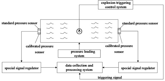
For defects in calibration methods applied to current underwater shock wave pressure measurement system in China, through related theoretical analyses, this paper designed an experimental method for the dynamic characteristics of underwater shock wave pressure. Refer to Figure1 for overall scheme of the experimental method. The scheme applies water shock tube with preload capacity, through detonating explosives by detonation control system, generates Quasi pulse pressure signal in water shock tube. Such signal cannot be acquired accurately based on physical relationship, so the comparative calibration method needs to be applied to treat the underwater shock wave pressure signal as the pressure drive signal, which then will be acted on the standard pressure sensor and the calibrated sensor respectively. In order to ensure that the characteristics of the shock wave pressures that acts on the standard pressure sensor and the calibrated underwater shock wave pressure sensor, the calibrated sensor and standard sensor shall be installed on the same end face of both sides of water shock tube. The preloading device is sealed and connected with pipes through a special screwed joint. When conducting the experimental calculation of dynamic characteristics for underwater shock wave pressure sensor, a static preload shall firstly be applied to the pipes through a pressure pump of preloading device, and then the explosion source shall be initiated at the special pressure and water proof detonator point in the pipeline center to generate an underwater explosion shock wave.
Fig. 1Overall scheme
Generally, the propellant form will only be considered when contact explosion or non-contact explosion near the propellant is studied, therefore, this experimental method considered only the explosive load and ignored the influence of propellant form on shock wave form. The incidence and reflection of shock wave in pipe and superposition between incident wave and reflected wave result in extremely complicated transmission form in the wave. However, as the explosion pressure wave reaches both ends of pipe, it will gradually develop into planar shock waves with steep front edge that are perpendicular to the axis [8, 9, 11]. The pressure shock wave transmits to both end surfaces and generates reflected shock wave on such end surface, as well as an excitation on the sensors installed on the end surface. Only if both ends of the circular tube are sealed and the applied preload value is larger than the maximum negative shock value of impulse response for sensor, can the “negative pressure” then be avoided. Applying different preload values can help analyze the dynamic characteristics of the sensor under different pressures.
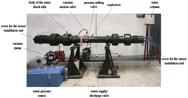
Refer to Fig. 2 for the actual structure of water shock tube designed in this paper. The tube body is a high-pressure resistant and axisymmetric structure; a special sealing flange can be used to combine different numbers of tube bodies. The tube length can be adjusted to comply with the requirements for different shock wave pressures in the experiment. The explosive material used to generate pressure is put in the geometric center of tube body to not only ensure a consistent display of characteristics of shock wave pressure acted on the standard pressure sensor and the calibrated pressure sensor, as well as to reduce errors.
Fig. 2Diagram of water shock tube
3. Experimental analysis for the dynamic characteristics of underwater shock wave pressure sensor
3.1. Time domain analysis
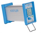
Kistler603C and Kistler6215 have been used as standard pressure sensor and calibrated sensor respectively in the experiment, as shown in Fig. 3, and Kistler5018A1000A charge amplifier has been customized, as shown in Fig. 4.
Fig. 3The standard sensor and the calibrated sensor
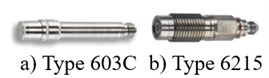
Fig. 4Kistler 5018 charge amplifier
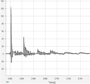
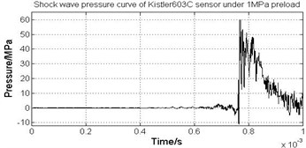
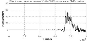
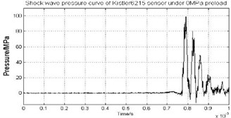
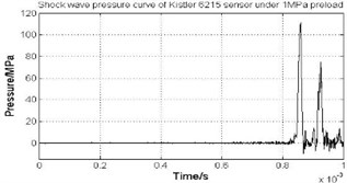
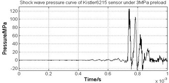
The above two sensors are assembled to the installation end cover of the water shock tube, as shown in Fig. 5. The preload is set to 3 MPa. Elsys TraNET high-speed data acquisition system was applied to collect data and its sampling rate can reach up to 10 MHz. Refer to Fig. 6 and Fig. 7 for the shock wave pressure curves of Kistler603C and Kistler6215.
According to Fig. 6 and Fig. 7, collected pressure wave form basically complies with the actual working conditions. A dissertation [7] studied the correlation between the structure of a water shock tube and the signal of the explosion shock wave in a water shock tube, and concluded that ideal signal of underwater shock wave can be formed when the length-diameter ratio of the water shock tube is not less than 16. In accordance to this finding, this paper used a water shock tube with a length of 3200 mm and a single tube with a length of 1600 mm, a diameter of 100 mm and a length-diameter ratio of 32.
There were several pulses that followed after the first pulse because of the echo resulting from reflection when the underwater shock wave generated from explosion reached an end surface of the water shock tube [9]. The transmission speed of the shock wave was about 1500 m/s, therefore, when the length of the shock tube is overly short, more echoes will be generated and the dynamic response curve of the sensor will be influenced. Therefore, the water shock tube is properly lengthened during the design.
Fig. 5Diagram showing the installation of sensors
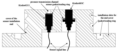
Fig. 6Shock wave pressure curve of Kistler603C
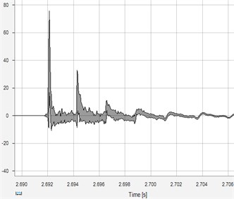
Fig. 7Shock wave pressure curve of Kistler6215
3.2. Frequency domain analysis
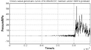
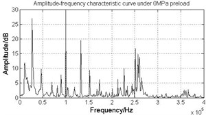
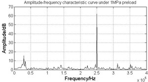
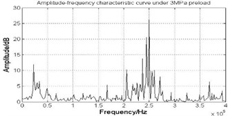
The experiment was conducted under a 0 MPa, a 1 MPa, and a 3 MPa preload. In order to avoid interference of the echo signals, only the first pulse in shock wave pressure curve of the sensor was selected for the spectral analysis. The collected data were then input into MATLAB. Refer to Fig. 8 for the waveform of the selected shock wave pressure curve acquired from the Kistler603C pressure sensor under the 0~3 MPa preload. Refer to Fig. 9 for the waveform of selected shock wave pressure curve of Kistler6215 pressure sensor under the 0~3 MPa preload. Fast Fourier transform (FFT) was conducted for the selected shock wave pressure data of Kistler603C and Kistler6215 respectively for spectral analysis, and then the calculation was implemented based on Formula to produce the amplitude-frequency curve of the comparative experiment data under the 0~3 MPa preload, as shown in Fig. 10. Comparing with Fig. 6, it could be seen that the trend basically complies with the built dynamic characteristics model.
From Fig. 8 and Fig. 9, it can be seen that preload offers a certain degree of influence on the shock wave pressure curves of the sensors, and the corresponding pressure offset may generate after the application of a certain amount of preload to increase the total pressure, therefore, a sensor with an appropriate range can be selected and used in experiment based on the specific preload value. According to Fig. 8, the peak value of Kistler603C is larger than Kistler6215 under same preload, because the shock wave will firstly pass through pressure hole and then act on Kistler6215. The actual working band range of Kistler6215 will significantly decline due to the influence of the pressure hole, as a result, the effective band of the side shock wave signal cannot be covered completely, resulting in large dynamic errors.
Fig. 8Shock wave pressure curve of Kistler603C pressure sensor under 0~3 MPa preload
a) 0 MPa preload
b) 1 MPa preload
c) 3 MPa preload
Fig. 9Shock wave pressure curve of Kistler6215 pressure sensor under 0~3 MPa preload
a) 0 MPa preload
b) 1 MPa preload
c) 3 MPa preload
Fig. 10Amplitude-frequency curve of comparative experiment data
a) 0 MPa preload
b) 1 MPa preload
c) 3 MPa preload
From Fig. 10, it can be seen that when the preload is 0 MPa (i.e, no preload applied), the amplitude-frequency curve becomes extremely disordered, because the sensor results in negative peak-clipping distortion, forming “negative pressure” [9]. Consequently, the dynamic response curve cannot normally and accurately reflect dynamic characteristics. When the top pressures are 1 MPa and 3 MPa, the natural frequency of calibrated pressure sensor (Kistler6215) is about 250 kHz, therefore, preload has no influence on the amplitude-frequency characteristics of the system. According to the specification of the sensor, the natural frequency of Kistler603C series’ sensors is about 400 KHz and the value will become small after the application of the reciprocal formula, therefore, it is not obvious in the waveform shown in Fig. 7. According to the specification, the natural frequency of Kistler6215 series’ sensors is about 240 KHz, which complies with the experimental results.
According to Fig. 10, the amplitude-frequency curve has a frequency concentration point in the range of 0~50 kHz resulting from the pipeline effect due to the installation structure of the Kistler6215 pressure sensor. According to Fig. 9 when Kistler6215 is installed on the end cover, its sensitive surface is designed with a sealed measurement hole as both a partition and a pressure transmission hole, instead of being directly exposed in front of shock wave. According to the specification of the sensor, such sealing measurement hole shall be set with depth of 2~3 mm and a diameter larger than 5 mm. The dimension of pressure hole in this device is 10×5 mm. Although the sealing measurement hole in this experiment is filled with special sealing silicone in which sound velocity is about 900 m/s, according to the simplified formula for the natural frequency of pipeline effect described in the specification of Kistler6215 sensor, , the natural frequency of the silicone filled in the sealing measurement hole is about 22.5 kHz, which is basically consistent with Fig. 10.
4. Conclusions
The experimental calculation method for the dynamic characteristics of underwater shock wave pressure sensor proposed in this paper can effectively calculate the dynamic transmission characteristics and natural frequency of the calibrated pressure sensor. Compared with the previous underwater explosion containers, the water shock tube used in this experiment features a small volume, low operation difficulty, and low cost. In addition, the water shock tube can, through the application of preload, simulate water depth and avoid damage on the sensors from reversed negative pressure. The pipeline effect occurred in this experiment can be eliminated or avoided through properly designing the installation structure for the sensors, as a result, measurement errors can be reduced.
According to the analysis in this paper, the following conclusions can be drawn:
1) Different preloads have significant influences on the time domain waveform of the sensor, and the pressure peak increases with the amount of applied preload. Therefore, sensors with an appropriate range can be selected based on the preload value.
2) A negative pressure will form when no preload is applied (preload = 0 MPa), the amplitude-frequency characteristics cannot be obtained accurately, or sensor may be damaged. Therefore, a certain amount of preload must be applied.
3) Different preloads have no influence on the calculation results of the amplitude-frequency characteristics of the calibrated sensor, and the dynamic characteristics are basically consistent.
4) The experimental calculation method for the dynamic characteristics of underwater shock wave pressure sensor proposed in this paper can provide guidance and reference for future works on pressure sensor calibration.
References
-
P. Cole, Underwater Explosion. Beijing: National Defence Industry Press, 1960.
-
J. H. Liu, X. T. Zhou, J. Q. Pan, and H. K. Wang, “The state analysis and technical development routes for the anti-explosion and shock technology of naval ships,” (in Chinese), Chinese Journal of Ship Research, Vol. 11, No. 1, pp. 46–56, 2016.
-
L. N. Li and D. W. Zhong, Dynamic Response Analysis and Optimization Design of Water Medium Explosion Vessels. Science Press, 2016.
-
Q. Dong, Z. B. Wei, T. Tang, and N. Zhang, “Influence of explosion depth on bubble pulsation of shallow water explosion,” (in Chinese), Chinese Journal of High Pressure Physics, Vol. 32, No. 2, pp. 85–93, 2018.
-
R. Ghoshal and N. Mitra, “Underwater explosion induced shock loading of structures: Influence of water depth, salinity and temperature,” Ocean Engineering, Vol. 126, pp. 22–28, Nov. 2016, https://doi.org/10.1016/j.oceaneng.2016.08.019
-
L. Li, Y. Hu, C. Fang, Y. You, K. Liu, and S. Huang, “Dynamic response prediction of underwater explosion vessels,” (in Chinese), IOP Conference Series: Earth and Environmental Science, Vol. 453, No. 1, p. 012040, Apr. 2020, https://doi.org/10.1088/1755-1315/453/1/012040
-
W. Z. Chen, C. D. Xu, D. R. Kong, T. W. Gu, and K. Zhao, “Characteristics of pulse pressure signal of water shock tube,” (in Chinese), Journal of Test and Measurement Technology, Vol. 31, No. 6, pp. 524–530, 2017.
-
M. W. Zhu and X. J. Wen, “Water shock tube for high pressure dynamic calibration,” (in Chinese), Journal of Experiments in Fluid Mechanics, No. 3, pp. 43–46, 1993.
-
C. K. Gong and Y. X. Li, “High-pressure dynamic calibration of water shock tube,” (in Chinese), Transducer and Microsystem Technologies, Vol. 5, pp. 61–63, 2008, https://doi.org/10.13873/j.1000-97872008.05.025
-
W. Lei, “Research on quasi-δ calibration technology of pressure sensor,” North University of China, 2014.
-
M. Venglár, M. Sokol, and R. Ároch, “Ambient vibration measurements of steel truss bridges,” Journal of Measurements in Engineering, Vol. 6, No. 4, pp. 234–239, Dec. 2018, https://doi.org/10.21595/jme.2018.20419
-
A. K. Sharma, A. Sharma, A. K. Raghav, and V. Kumar, “Analysis of free vibration of non-homogenous trapezoidal plate with 2D varying thickness and thermal effect,” Journal of Measurements in Engineering, Vol. 4, No. 4, pp. 201–208, Dec. 2016, https://doi.org/10.21595/jme.2016.16378
About this article

