Abstract
Under the influence of transient high temperatures, piezoelectric shock wave pressure sensors produce a thermal shock response that affects the accurate acquisition of the pressure signal. In order to analyse the effect of thermal shock on the measurement of piezoelectric pressure sensors, a rectangular pulse temperature of 1800 ℃ with a duration of 30 ms was applied to the surface of the sensor diaphragm by the method of thermal coupling, and the temperature distribution inside the sensor under transient thermal excitation was explored, and the thermal expansion displacement and preload change of the sensor were analysed. The results show that: the temperature rise of the piezoelectric crystal is small and does not reach the Curie point temperature, which has less influence on the material properties of the piezoelectric crystal; the thermal shock response of the piezoelectric pressure sensor is mainly caused by the thermal deformation of the pressure-sensing diaphragm, which affects the stability of the preload inside the sensor and leads to a negative signal output from the sensor. This study provides a reference for the research of thermal shock suppression methods for piezoelectric pressure sensors.
1. Introduction
Piezoelectric pressure sensors are widely used for shock wave pressure measurements under destructive conditions due to their good dynamic characteristics and less susceptibility to optical signals [1]. However, piezoelectric pressure sensors are not thermally protected, and under the action of transient high temperatures the sensors will generate temperature drift errors. Therefore, it is necessary to do further research on the thermal shock response of piezoelectric shock wave pressure sensors to better assess the reliability and applicability of piezoelectric pressure sensors in thermal shock environments.
Currently, many studies have been done by scholars on the thermal shock response side of piezoelectric pressure sensors. Krause et al. [2] showed that transient high temperatures cause mechanical deformation of piezoelectric pressure sensor diaphragms and housings, which can exert either positive or negative forces on piezoelectric crystals, thus changing the sensor readings. The degree of response of six different types of pressure sensors under the influence of thermal shock was evaluated by means of a developed stainless steel ball ignition system. Wu et al. [3] found that when the piezoelectric pressure sensors were heated by heat flow, the measurement data of the sensors would be distorted. The initial analysis was that the thermal expansion of the sensor pressure-sensing diaphragm resulted in a reduction of the piezoelectric crystal preload, and that the increase in the temperature of the piezoelectric crystal produced a charge output. By placing the piezoelectric pressure sensor and the thermocouple temperature sensor into 60 °C water at the same time, the thermal response curve and temperature curve of the sensor were recorded, and a thermal protection method of pasting plastic adhesive paper was given.
In summary, scholars at home and abroad have found that thermal shock has a certain effect on the measurement accuracy of piezoelectric pressure sensors in practical work, and verified through the corresponding experiments, but the analysis of piezoelectric pressure sensors to generate the thermal shock response has not been further studied, and there is no systematic elaboration of this process. In this study, we will start from the structure of piezoelectric pressure sensors and the characteristics of piezoelectric materials, and further analyse the reasons for the generation of thermal shock response of piezoelectric shock wave pressure sensors as well as the effects of thermal shock on the measurement of the sensors through thermodynamic simulation calculations.
2. Piezoelectric shock wave pressure sensor structure
In this paper, a typical piezoelectric shock wave pressure sensor is used as a research object for simulation and analysis. From literature [4], the internal structure of the sensor is shown in Fig. 1.
The main structure of piezoelectric pressure sensor includes pressure sensing diaphragm, case, force transmitting block, thin-walled sleeve, piezoelectric plate, electrode sheet and acceleration compensation mass block, etc. The core element of piezoelectric pressure sensor is piezoelectric effect, the electrodes are made of gold. The sensor diaphragm material is invar, the electrode material is gold, the piezoelectric plate is alpha quartz, and the rest of the structural material is 17-4 Stainless. The core element of the piezoelectric pressure sensor is the piezoelectric plate with piezoelectric effect, which can convert the measured pressure signal into an electrical signal. Common piezoelectric pressure sensors are diaphragm-type structures, where the diaphragm is mainly responsible for the following three tasks: transmitting pressure, providing pre-pressure and achieving a seal. The pressure-sensing diaphragm acts vertically on the piezoelectric plate, which generates an electrical charge and outputs an electrical signal through the electrodes. In order to obtain a good linear performance of the sensor, the pressure-sensing diaphragm is generally welded to the housing cylinder using a preloaded compression package to reduce the gap between the diaphragm and the piezoelectric crystal stack.
Fig. 1Internal structure of the sensor
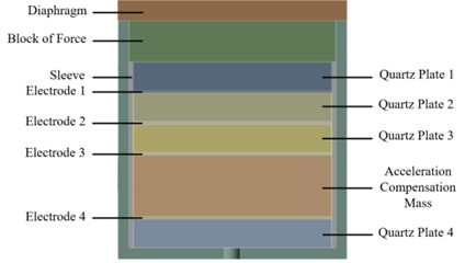
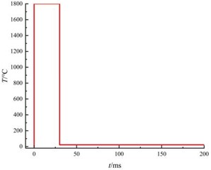
Fig. 2Temperature load
3. Numerical simulation analysis
In order to clarify the internal temperature change of the piezoelectric pressure sensor after thermal shock and the change of preload force caused by the temperature, the sensor model was established in Ansys Workbench, and the Transient Thermal and Transient Structural modules were used to perform transient thermal simulation analysis and thermal coupling simulation analysis of the sensor.
3.1. Numerical simulation analysis
Considering that the temperature at each measurement point of the explosion field is not gradually decaying after reaching the peak temperature at a certain moment, but there are multiple temperature rise process, the peak temperature tends to be the result of the accumulation of multiple times [5], in the sensor diaphragm surface to impose the peak temperature of 1800 °C and the duration of the role of the time of 30 ms rectangular pulse temperature, as shown in Fig. 2, and at the same time, set the ambient temperature of 22 °C. From the literature [6], the sensor surface temperature and heat flow temperature and convective heat transfer coefficient has a great relationship, set the diaphragm surface convective heat transfer coefficient of 10000 W/m2·°C. Due to the chemical or conventional munitions explosion shock wave duration of milliseconds [7-8], the application value of the study of the effect of long time transient temperature on the sensor is not high, the solution time is set to 200 ms.
In order to further simplify the simulation model and save computational resources, two symmetry planes, - and -, are set up to construct a 1/4 simulation model and the mesh size of the electrode sheet is 0.05 mm, and the mesh size of the rest of the parts is 0.1 mm.
According to Hooke's law, the relationship between the stress and strain on each layer of the thin plate of the sensor is as follows:
where: is the modulus of elasticity; subscript is the -th sheet; is the linear expansion coefficient; is the strain; is the temperature difference.
The physical parameters of each material solved by simulation are shown in Table 1.
Table 1Material physical parameters
Materials | Young’s modulus / GPa | Coefficient of thermal expansion / (10-6/℃) | Poisson’s ratio | Thermal conductivity / W·(m·℃)-1 |
Invar | 134 | 1.5 | 0.25 | 11 |
17-4 Stainless | 197.2 | 11.1 | 0.272 | 15.9 |
Quartz | 76.5 | 7.97 | 0.17 | 11.7 |
Gold | 79 | 14.2 | 0.44 | 317 |
3.2. Transient thermal analysis
The temperature transfer cloud of the sensor subjected to transient thermal shock is shown in Fig. 3.
Fig. 3Temperature transfer cloud image (unit: ℃)

a) 30 ms
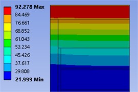
b) 100 ms
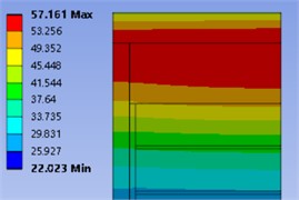
c) 200 ms
From the simulation results, it can be seen that the sensor is subjected to transient thermal shock, and the heat is gradually transferred to the internal structure through the diaphragm at the front end of the sensor. Within 30 ms of the thermal action, the heat is mainly transferred within the diaphragm. The thermal excitation temperature disappears at 30 ms of thermal action, and the maximum temperature of the diaphragm decreases from 1800 °C to 451.38 °C. The temperature of the diaphragm is also reduced by the rectangular pulse. After the disappearance of the rectangular pulse temperature, the heat is still transferred inside the sensor and the maximum internal temperature keeps decreasing. The maximum temperature of the diaphragm surface is 92.28 °C at 100 ms, and a certain temperature rise also occurs inside the sensor. At 200 ms the maximum temperature appeared in the contact area between the diaphragm, the housing and the force transfer block, and the maximum temperature decreased to 57.2 °C. The maximum temperature of the diaphragm, the housing and the force transfer block was 57.161 °C. In order to accurately obtain the temperature change in the two contact areas, temperature probes were set up on the lower surface of the diaphragm and the upper surface of plate 1 to monitor the surface temperature change. The temperature change curves of the two contact regions are shown in Fig. 4.
Fig. 4Temperature change curve
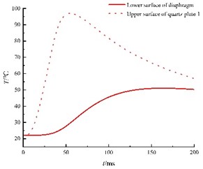
From the monitoring results, it can be seen that under the transient thermal excitation of the sensor diaphragm, the temperature of the lower surface of the diaphragm rises sharply, and reaches a maximum temperature of 96.88 °C at 53.3 ms. With the disappearance of the transient thermal excitation and the heat conduction inside the sensor, the temperature of the lower surface of the diaphragm first decreases sharply and then slowly decreases to the ambient temperature, and the temperature of the lower surface of the diaphragm decreases to 57.5 ℃ at 200 ms. After 21.6 ms of transient thermal excitation, the temperature rise on the upper surface of plate 1 started to appear. At 167 ms, the temperature of the upper surface of plate 1 increased to a maximum temperature of 51.04°C and then decreased slowly.
The phenomenon that the polarisation intensity changes due to the uniform temperature change of the crystal is called the pyroelectric effect of the crystal, but the pyroelectric effect occurs on the pyroelectric body, and it is known that the sensitive element of the common explosive shock wave piezoelectric pressure sensor is -quartz, and the charge centre of the -quartz does not displace due to the heat, so there is no change in the total electric moment, and there is no pyroelectricity, and there is no need to take into consideration the influence of the pyroelectric effect. However, when the temperature of α quartz reaches the Curie point temperature of 573 °C, the quartz crystal becomes quartz due to the change in polarisation intensity that occurs as a result of the temperature change, and the piezoelectric properties of the quartz crystal begin to be lost. The maximum temperature rise of the piezoelectric plate 1 is 29.04 °C, which has not reached the Curie point of the quartz phase transition, and there is no need to consider that the quartz morphology has changed. The piezoelectric coefficient of the piezoelectric crystal also hardly changes with temperature in the room temperature range. In the range of 20 to 200 °C, the piezoelectric coefficient decreases by only 0.016 % for every 1 °C increase in temperature, and the temperature change of plate 1 is 29.04 °C, which does not have much effect on the piezoelectric coefficient.
3.3. Thermal coupling analysis
In order to analyse the thermal expansion displacement of the sensor after the transient thermal shock and its impact on the pressure measurement, the internal temperature field data of the sensor obtained from the Transient Thermal solution is coupled to the Transient structural simulation in order to carry out the thermodynamic analysis, and the step size of the solution is kept the same as that of the Transient Thermal setting, and the results of the simulation are shown in Fig. 5.
Fig. 5Cloud image of axial displacement of the sensor (unit: mm, deformation amplified 100 times)
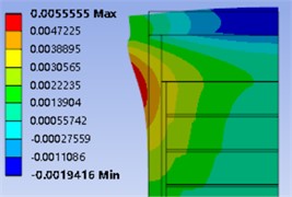
a) 30 ms
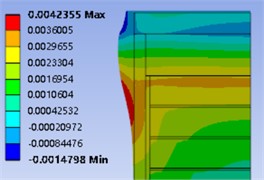
b) 100 ms
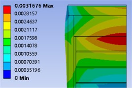
(c) 200 ms
Combined with the temperature change cloud diagram inside the sensor, it can be seen that due to the uneven temperature distribution inside the sensor and the different coefficients of thermal expansion of each component, the axial displacements of each part of the sensor have large differences. When the transient temperature is applied for 30 ms, the heat is mainly concentrated inside the diaphragm, which leads to tensile stresses in the pressure-sensitive diaphragm as it expands to the air domain after being heated; at this time, the temperature rise of the wall of the housing cylinder is small, and its deformation is mainly caused by the deformation of the diaphragm, which generates compressive stresses inside it. At 100 ms, the maximum temperature rise is concentrated in the contact area between the diaphragm, the housing and the force transmitting block, where the element is still expanding outward, but the axial displacement is reduced due to the lower temperature. At 200 ms, the thermal expansion displacement generated by the sensor basically disappears, but due to the inconsistency of the thermal expansion coefficient of each structure, after the rapid disappearance of the external temperature, the thermal expansion displacement of the central part of the diaphragm is firstly restored, while the welded portion of the diaphragm and the shell is still in the state of expansion towards the air domain, which makes the sensor subjected to compressive stresses internally.
Fig. 6Change of preload on the upper surface of plate 1
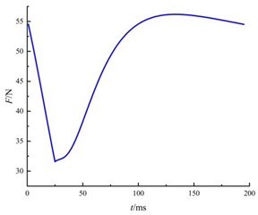
In order to analyse the effect of thermal expansion on the pressure signal output, an axial force of 500 N was applied to the sensor diaphragm surface as a preload force. A monitoring point was set up on the upper surface of plate 1, and the variation curve of the preload force inside the sensor is shown in Fig. 6.
Due to the action of the housing and the thin-walled sleeve, the 500 N preload applied on the surface of the diaphragm does not act completely on the piezoelectric plate, and the preload on the upper surface of the plate 1 is 54.55 N at the initial moment, and it rapidly decays to 31.585 N within 30.1 ms. Combined with the sensor displacement cloud diagram, it can be seen that, when a transient thermal load is applied on the surface of the piezoelectric diaphragm, the centre of the piezoelectric diaphragm is rapidly heated and expands outward, resulting in the internal preload of the sensor being de-loaded. This leads to the preload reduction inside the sensor. For the piezoelectric plate, the surface charge output is mainly affected by the axial force, which is the product of the axial force and the piezoelectric coefficient, and the sensor outputs a negative signal. With the disappearance of the transient thermal load and the heat conduction inside the sensor, the preload force quickly returns to the initial value after the diaphragm shrinks. However, due to the slow contraction at the weld between the shell and the diaphragm, the centre of the diaphragm shifts from tension to compression, resulting in the internal preload continuing to rise to 56.187 N. With the complete disappearance of the internal thermal load, the preload returns to the initial value. The above simulation analysis reveals the serious impact of transient thermal shock on piezoelectric pressure sensors, and the interference of thermal shock cannot be ignored in dynamic pressure testing.
4. Conclusions
In this paper, starting from the structure of piezoelectric pressure sensor and the characteristics of piezoelectric material, the thermal shock response of piezoelectric pressure sensor is analysed by simulation, and the following conclusions are drawn: within 30 ms of the 1800 °C rectangular pulse temperature, the heat is mainly concentrated in the sensor's pressure sensing diaphragm, and there is almost no temperature rise inside the sensor. The maximum temperature on the upper surface of plate 1 is 29.04 °C, which does not reach the Curie point temperature and has little effect on the piezoelectric coefficient. The diaphragm was heated and expanded, leading to the unloading of the preload, and the pressure sensor showed a negative signal; the diaphragm was cooled and contracted, and the negative signal was attenuated and recovered to the initial value slowly. Therefore, under the premise of not affecting the pressure transmitting characteristics of the pressure sensor, thermal suppression measures can be taken on the sensitive surface of the pressure sensor to slow down the transfer of heat to accurately obtain the shock wave pressure signal.
References
-
G. Y. Li, “Research on thermal protection and its influence in dynamic pressure test of artillery,” Nanjing University of Science and Technology, 2020.
-
T. Krause, M. Meier, and J. Brunzendorf, “Influence of thermal shock of piezoelectric pressure sensors on the measurement of explosion pressures,” Journal of Loss Prevention in the Process Industries, Vol. 71, p. 104523, Jul. 2021, https://doi.org/10.1016/j.jlp.2021.104523
-
S. Wu, H. Chen, J. H. Gu, and H. R. Yu, “A thermal protection method for piezoelectric pressure sensor,” (in Chinese), Chinese Science Bulletin, No. 8, pp. 866–869, 2007.
-
Y. Shi, D. Kong, and X. Ma, “Research on thermal protection of piezoelectric pressure sensor for shock wave pressure measurement in explosion field,” Sensor Review, Vol. 43, No. 3, pp. 208–220, May 2023, https://doi.org/10.1108/sr-11-2022-0407
-
P. Cheng, J. Cheng, and G. Yan, “Experiment research on thermal shock effect of piezoelectric pressure transducers,” Transducer and Microsystem Technologies, No. 2, pp. 27–29, 2006, https://doi.org/10.13873/j.1000-97872006.02.009
-
L. Q. Wang, F. Shang, J. W. Zhang, D. R. Kong, and R. Wang, “Numerical simulation experimental study on damage capability of high energy explosive,” Journal of Test and Measurement Technology, Vol. 35, No. 1, pp. 6–11, 2021.
-
J. R. Ji, J. J. Su, Y. P. Liu, J. J. Yan, and G. Q. Wang, “experimental study on explosive thermal effect of the non-ideal explosive,” Chinese Journal of Explosives and Propellants, Vol. 33, No. 4, pp. 49–52, 2010, https://doi.org/10.14077/j.issn.1007-7812.2010.04.012
-
H. J. Zhou, H. Q. Ren, S. J. Yu, J. Y. Chen, and Y. D. Cao, “Research review of air shock wave pressure measurement technology,” Protective Engineering, Vol. 41, No. 3, pp. 61–69, 2019.
Cited by
About this article

The authors have not disclosed any funding.
The datasets generated during and/or analyzed during the current study are available from the corresponding author on reasonable request.
The authors declare that they have no conflict of interest.
