Abstract
A single-sensor differential pressure vector hydrophone based on a radially polarized piezoelectric circular tube structure is proposed, which can realize the azimuth angle of the incident acoustic wave by using the scalar information of the underwater sound field through a single sensor without any priori conditions. It has the characteristics of simple structure and low cost. The proposed hydrophone is improved based on the piezoelectric circular tube structure. And its piezoelectric ceramics are divided into eight parts. Through the different response voltages of each part, the underwater sound field scalar information received by a single sensor is used, combined with signal processing algorithms, the azimuth angle of the incident sound wave is estimated. The finite element method is used to complete the simulation of the hydrophone, and the simulation results are analyzed and fitted. Through the mockup test, comparing the results, and combining with the fitting formula, it is verified that the hydrophone can estimate the azimuth angle of the incident sound wave without any priori conditions.
Highlights
- The Single-sensor pressure-gradient piezoelectric cylindrical tube vector hydrophone can realize the estimation of the azimuth angle of the incident sound wave without any prior conditions.
- The designed hydrophone is improved based on the piezoelectric circular tube transducer structure. Fit the finite element analysis results to get the fitting formula. The feasibility of the fitting formula is verified by the simulation results.
- The feasibility of the fitting formula is verified again by the test results of the prototype, and the reliability of the designed hydrophone to the azimuth angle of the incident sound wave is verified.
1. Introduction
Piezoelectric hydrophones convert acoustic signals into electrical signals through the piezoelectric effect, so as to achieve the purpose of acquiring underwater information [1]. Traditional piezoelectric hydrophones are all scalar hydrophones and have no directional sensitivity. At present, the identification of sound wave direction is usually realized by hydrophone array, and the method of beamforming is used to identify the target position [2], [3]. Using the hydrophone array to estimate the sound wave direction requires a large number of hydrophones, which increases the cost of use and complicates signal processing. A vector hydrophone is a type of receiving transducer that can simultaneously measure scalar and vector information in the sound field [4]. At present, the research on vector hydrophone mainly increases its sensitivity and bandwidth by improving the structure [5]-[7], and there are also studies applying MEMS to vector hydrophone [8]. Although the vector hydrophone has high receiving sensitivity, its internal structure is complex and the production cost is high. For the single vector hydrophone to locate the target, it needs the support of complex algorithms or models [9], [10].
Aiming at the above problems, a single-sensor differential pressure vector hydrophone based on piezoelectric circular tube structure is innovatively proposed. It has the characteristics of simple structure and low cost. The hydrophone is simulated by finite element, the simulation results are analyzed, the simulation results are fitted, and a prototype is made for experiments, the experimental results are compared with the simulation results, and the calculated azimuth is compared with the real azimuth to verify the reliability of the fitting formula and the feasibility of the designed hydrophone to estimate the azimuth angle of the incident sound wave are discussed.
2. Principle and modeling
Compared with the traditional piezoelectric circular tube hydrophone, the piezoelectric ceramic of the proposed pressure-difference vector hydrophone based on the single circular tube piezoelectric ceramic is divided into 8 parts, as shown in Fig. 1(a), the piezoelectric ceramic model was built in COMSOL software. The 8 equal parts of the piezoelectric ceramic are all radially polarized, but the polarization directions of each adjacent two parts are opposite. The 8 parts divided by piezoelectric ceramics are respectively the 1st to 8th quadrants, of which the 1st, 3rd, 5th and 7th quadrants are polarized radially outwards, and the 2nd, 4th, 6th and 8th quadrants are polarized radially inwardly. When acoustic waves at different azimuth angles are incident on the piezoelectric ceramics, the different polarization directions of each quadrant will lead to different response voltages, and the time for each quadrant to generate the response voltage is different.
Since the purpose of the hydrophone is to roughly estimate the direction of the incident sound wave, for the convenience of calculation, the metal cover, transition body, metal base and bolts can be ignored in the modeling. Secondly, only one half of the piezoelectric circular tube needs to be constructed, which reduces the amount of calculation. According to the above principle analysis, the piezoelectric circular tube is modeled by using COMSOL software, as shown in Fig. 1(b), the constructed finite element model. Table 1 provides the material of piezoelectric circular tube.
Table 1Piezoelectric tube and material
Part | Material |
Piezoelectric circular tube | PZT-5H |
Fig. 1a) Piezoelectric ceramics model; b) The finite element model of hydrophone
a)
b)
3. Simulation analysis
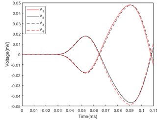
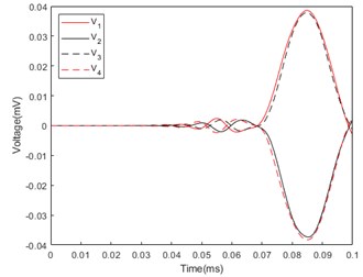
Based on the above working principle, the finite element simulation analysis was carried out using COMSOL according to the model built in Fig. 1(b). Incident acoustic waves are incident from azimuthal angles of 45° to 135°, and the response voltages generated by piezoelectric ceramics in four quadrants are analyzed. Let the response voltages generated by the 1st, 2nd, 3rd and 4th quadrants be , , and . Fig. 2 shows the first two cycles of the response voltage generated by the 1st, 2nd, 3rd and 4th quadrant piezoelectric circular tubes under the conditions of incident acoustic waves of 45°, 75° and 115°.
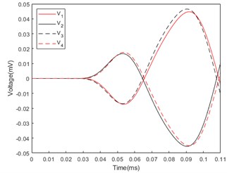
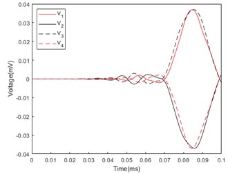
In Fig. 2(a), the sound wave is incident at the azimuthal angle of 45°, the first and fourth quadrants of piezoelectric ceramics first generate voltages and , and the second period peaks of the generated voltages are almost the same. Since the polarization directions of the two quadrants are opposite, the sign is opposite. The second and third quadrants generate voltages and slightly later than the first and fourth quadrants, and the second cycle peak value of the generated voltage signal is almost the same with opposite signs. The second cycle peak value of and is slightly larger than the second cycle peak value of and . In Fig. 2(b), the sound wave is incident at the azimuthal angle of 75°. Compared with the voltage generated on the piezoelectric ceramic by the sound wave incident at the azimuthal angle of 45°, the time difference between the voltage signals , and , is smaller, and the second cycle peak difference is smaller. In Fig. 2(c), the sound wave is incident at the azimuthal angle of 115°, and the sound wave reaches the second and third quadrants first, so the voltage signals and are generated a little earlier than and , and the second cycle peaks of the response voltage and Slightly larger than the second cycle peaks of and .
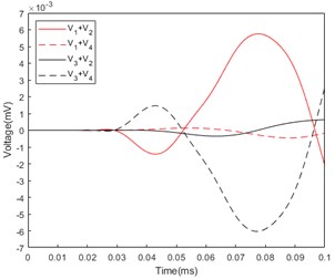
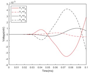
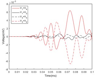
The peaks of the voltage signals in the four quadrants are processed, and the relationship between the results and the azimuth angle of the incident acoustic wave is determined. After trying, there is a good regular relationship between the normalized value of the maximum value of the absolute value of the second cycle peak absolute value of the , , and curves and the azimuth angle of the incident sound wave. Fig. 3 shows the response voltages and curves of each quadrant of the piezoelectric circular tube under different azimuth angles of incident sound waves.
Fig. 2Response voltage of piezoelectric ceramic tube: a) Azimuth angle of incident sound wave: 45°; b) Azimuth angle of incident sound wave: 75°; c) Azimuth angle of incident sound wave: 115°
a)
b)
c)
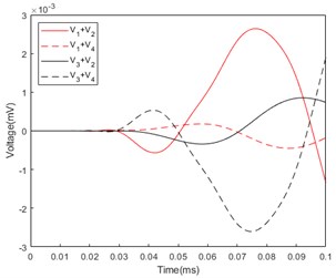
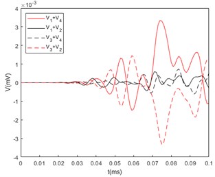
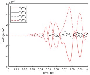
In Fig. 3(a), the azimuthal angle of the incident acoustic wave is 45°, and the curve fluctuation of is less than 10-3 mV, which is close to zero, because the response voltages of the first and fourth quadrants. The magnitudes are almost equal and the signs are opposite. Similarly, the curve fluctuation of is smaller than 10-3mV for the same reason. The peak value of the second cycle of is positive, and the peak value of the second cycle of is negative. In Fig. 3(b), the azimuthal angle of the incident acoustic wave is 75°. The sum of the voltage peaks is slightly smaller than when the incident azimuth angle is 45°. In Fig. 3(c), the azimuthal angle of the incident sound wave is 115°, and it reaches the second and third quadrants first. The peak value of the second cycle of is negative, and the peak value of the second cycle of is positive.
Through the analysis of the above results, the relationship between the normalized value of the absolute value of the second cycle peak value of the piezoelectric ceramic voltage sum curve and the azimuth angle of the incident acoustic wave can be determined and fitted to obtain a fitting formula such as Eq. (1):
where is the normalized value of the absolute value of the second cycle peak value of the piezoelectric ceramic voltage sum curve, and is the azimuth angle of the incident acoustic wave.
Fig. 3Sum of piezoelectric ceramic tube response voltage: a) Azimuth angle of incident sound wave: 45°; b) Azimuth angle of incident sound wave: 75°; c) Azimuth angle of incident sound wave: 115°
a)
b)
c)
Fig. 4Azimuth angle fitting curve
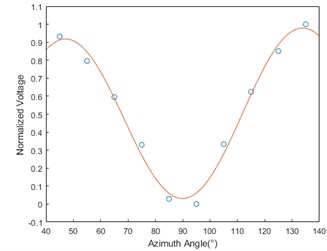
Using Eq. (1), the azimuthal angle of the incident acoustic wave that produces the response voltage can be calculated. As shown in Table 2, the sound wave incident at any azimuth angle, the error between the calculation result and the simulation result is within ±2°, which confirms the reliability of the formula. Fig. 4 is the azimuth fitting curve, which shows the error between the simulation points of the real azimuth and the curve of Eq. (1).
Table 2Calculate the azimuth angle and the true azimuth angle
True azimuthal angle (°) | Voltage sum normalized value | Calculate azimuthal angle (°) |
60 | 0.703488 | 61.1 |
76 | 0.151163 | 77.7 |
120 | 0.746124 | 119.4 |
4. Experimental tests
The pressure-difference vector hydrophone based on single-tube piezoelectric ceramics is mainly composed of a metal cover, piezoelectric ceramics, and a metal base, and is clamped by bolts. The material selection of each component is shown in Table 3.
Fig. 5Hydrophone mockup
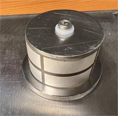
Table 3Hydrophone components material selection
Parts | Material |
Metal cover | 316 stainless steel |
Piezoelectric Ceramics | PZT-5H |
Metal base | 316 stainless steel |
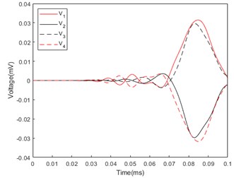
Fig. 6Response voltage curve of mockup: a) Azimuth angle of incident sound wave: 45°; b) Azimuth angle of incident sound wave: 75°; c) Azimuth angle of incident sound wave: 115°
a)
b)
c)
In addition, epoxy resin is needed as a vibration isolation and decoupling layer between the piezoelectric ceramics, the metal cover and the metal base. The mockup of Single-sensor pressure-gradient piezoelectric cylindrical tube vector hydrophone is shown in Fig. 5. The mockup is placed in a pool, and the sound source is placed in a water area with a fixed elevation angle relative to the prototype and an azimuth angle of 45° to 135°. The response voltages generated on the prototype at different azimuthal angles are collected, as shown in Fig. 6. Since Eq. (1) requires the normalized value of the maximum value of the sum absolute value of the response voltage, the above data is processed to obtain the response voltage sum curve of the prototype as shown in Fig. 7.
Because the simulation is carried out under ideal conditions, and the prototype experiment has many influencing factors such as reverberation, noise, assembly, material, etc. The experimental results are different from the simulation results, but the overall curve trend and the appearance time of the response voltage are the same as the theoretical analysis is consistent with the simulation analysis. The experimental results are normalized and substituted into Eq. (1) to obtain the calculated azimuth. As shown in Table 4, it can be seen that the error between the calculated azimuth and the real azimuth is within ±3°.
Fig. 7Sum of the mockup’s response voltage curve: a) Azimuth angle of incident sound wave: 45°; b) Azimuth angle of incident sound wave: 75°; c) Azimuth angle of incident sound wave: 115°
a)
b)
c)
Table 4Comparison of the real azimuth angle of the mockup and the calculated azimuth angle
True azimuth angle (°) | Calculate azimuth angle (°) |
45 | 43.6 |
75 | 72.4 |
115 | 115.9 |
5. Conclusions
A differential pressure vector hydrophone based on single-tube piezoelectric ceramics is proposed, which can measure the azimuth angle of incident acoustic waves without any prior conditions. After simulation analysis and fitting the formula for calculating the azimuth angle of the incident sound wave according to the simulation results, the error between the azimuth angle calculated by this formula and the real azimuthal angle is less than ±2°. After mockup production and testing, the error between the calculated azimuthal angle and the real azimuth angle calculated by the response voltage obtained by the prototype through the fitting formula is within ±3°. Through the above simulation and test, the reliability of the fitting formula is verified, and the feasibility of measuring the azimuth angle of incident acoustic waves with the single-sensor pressure-gradient piezoelectric cylindrical tube vector hydrophone is also verified.
References
-
J. Xu, S. Lin, Y. Ma, and Y. Tang, “Analysis on coupled vibration of a radially polarized piezoelectric cylindrical transducer,” Sensors, Vol. 17, No. 12, p. 2850, Dec. 2017, https://doi.org/10.3390/s17122850
-
Nan Zou and A. Nehorai, “Circular acoustic vector-sensor array for mode beamforming,” IEEE Transactions on Signal Processing, Vol. 57, No. 8, pp. 3041–3052, Aug. 2009, https://doi.org/10.1109/tsp.2009.2019174
-
Shen Yiming and Shen Zhengyi., “A linear array starboard and starboard resolution method based on ternary weighted beamforming,” (in Chinese), Acoustics and Electronic Engineering, No. 3, pp. 12–14, 2019.
-
Chen Hongjuan, Vector Sensor. Harbin, China: Harbin Engineering University Press, 2006, pp. 8–12.
-
Wang Jiarong et al., “Performance modeling and analysis of a piezoelectric single crystal vector hydrophone.,” (in Chinese), Piezoelectric and Acousto-Optic, Vol. 41, No. 4, pp. 552–556, 2019.
-
Silvia M. T. and Richards R. T., “A theoretical and experimental investigation of low-frequency acoustic vector sensors,” in Oceans ’02 MTS/IEEE, 2002, https://doi.org/10.1109/oceans.2002.1191918
-
Liu Shuang., “Research on a new vector hydrophone,” (in Chinese), Harbin Engineering University, 2016.
-
S. Shi et al., “Design and fabrication of a novel MEMS piezoelectric hydrophone,” Sensors and Actuators A: Physical, Vol. 313, p. 112203, Oct. 2020, https://doi.org/10.1016/j.sna.2020.112203
-
Guo Yecai, Han Jinjin, and Wang Chao., “Single vector hydrophone multi-sound source localization algorithm based on fourth-order moments,” (in Chinese), Journal of Sichuan University (Natural Science Edition), Vol. 55, No. 4, pp. 733–738, 2018.
-
X. Sun, X. Jia, Y. Zheng, and Z. Wang, “An adaptive model for the location of low-frequency sound sources in shallow sea environments,” Applied Acoustics, Vol. 171, p. 107569, Jan. 2021, https://doi.org/10.1016/j.apacoust.2020.107569
About this article

This work was supported by Science and Technology Project of Pilot National Laboratory for Marine Science and Technology (Qingdao) (2021WHZZB0304).
