Abstract
In this work, thickness variations are introduced around the circumference of a piezoelectric cylindrical shell. The aim is to investigate the vibration characteristics of the shells and the effect of these step-thickness variations on the mode shape of vibration. These thickness variations require stress distribution analysis as well to avoid failure of the cylindrical shell. To this aim, two configurations of stepped-thickness shells with two and three circumferential thickness variations are investigated using FEA software, ANSYS. The results show that these steps assist in localizing vibration in the thin sections and excite mode shapes having the same circumferential wave number as the number of thickness variations. This can be a suitable approach to control and forcibly excite certain vibration mode shapes, which might be required for some applications.
1. Introduction
For the past few decades, piezoelectric transducers have been thoroughly employed for many different industrial and biomedical applications [1]. Depending on the application, the requirements for these transducers vary. In many of these applications, it is required that the transducer emits or receives ultrasonic waves within a gaseous medium. The transducer has acoustic impedance mismatch with the medium. To diminish this, it is required to increase vibration amplitude and generate radiation with high directivity [2]. Therefore, to improve performance of these transducers and tune them for each specific application, ongoing research has been conducted on these transducers.
Geometry and vibration modes have strong effects on the performance of a transducer. To study these effects, a lot of research was conducted on various geometries such as plates and cylindrical shells [2-15]. While stepped plates were investigated and their superiority over flat plates was completely proven [2, 3, 5, 6, 16-18], stepped-thickness cylindrical shells have not been thoroughly investigated. The mode of deformation for axially stepped cylindrical shells was investigated for static and dynamic loads and it was found that the thin, stepped sections effectively localized deformation [19-21]. Also, the authors investigated acoustic and radiation characteristics of cylindrical shells with axial steps [22, 23]. Although vibration of cylindrical shells with circumferential steps was theoretically studied [24], the literature lacks comprehensive investigations on vibration and acoustic radiation of shells with circumferential steps. To this aim, this work aims at investigating vibration characteristics of circumferentially stepped-thickness piezoelectric cylindrical shells which is required for improving the performance of these shells used as ultrasonic transducers. Further, stress distribution is considered as it affects the final decision and design considerations for these transducers.
2. Material and simulation details
We chose a PZT-5L piezoelectric tube (from Nanjing Hanzhou Technologie CO., LTD) the material properties of which are tabulated in Table 1 [25]. The density is 7600 kg/m3. The dimensions are 30 mm outside diameter, 26 mm inside diameter and 50 mm length.
To perform our simulations, ANSYS R15 Version 15.0.7 was employed together with an extension ‘PiezoAndMEMS’ to define piezoelectric material and its properties. The first step was to perform harmonic analysis on a tube with a uniform thickness. This was used as reference for comparison. We considered Simply Supported boundary condition. For exciting the piezoelectric shell, 36 V was applied to the electrodes of the transducer. The applied voltage can also be varied. The electrodes are too thin in comparison with the transducer dimensions; hence, they were not considered in our simulations.
Table 1Material properties of PZT-5L [25]
Elastic stiffness (Pa) ×1010 | Stress constant (C/m2 or N/V.m) | Relative Permittivity | |||
12.1 | –5.4 | 916 | |||
7.54 | 15.8 | 830 | |||
7.52 | 12.3 | ||||
11.1 | |||||
2.11 | |||||
C = Coulomb; N = Newton; V = Volt; m = Meter | |||||
Meshing quality considerably affects the precision of our results. Mesh skewness is the main mesh quality metric. It compares the element distortion with the ideal shape and reports a number within the range of 0 to 1. The limit is 0.95 and lower values represent better meshing (0.5-0.8 is a good mesh, 0.25-0.5 is considered a very good meshing and less than 0.25 is excellent [26]). To make sure meshing is done satisfactorily and results are reliable, mesh skewness is presented in Table 2.
Table 2Mesh skewness for all specimens
Skewness | Uniform-thickness | 2 Circumferential steps | 3 Circumferential steps | ||
External | Internal | External | Internal | ||
Average | 0.25 | 0.31 | 0.31 | 0.3 | 0.29 |
Max | 0.93 | 0.72 | 0.75 | 0.68 | 0.76 |
3. Design of stepped-thickness shells
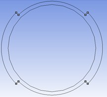
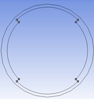
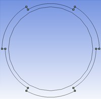
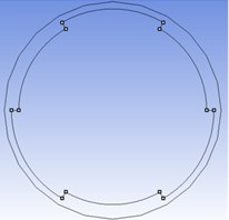
As discussed earlier, it is intended to investigate feasibility of exciting mode shapes with different circumferential wave numbers such as two and three. To this aim, a uniform-thickness shell was investigated first within low ultrasound range of 25 kHz to around 60 kHz. The harmonic analysis results revealed that there occurs no mode shape with circumferential wave number of two or three within this frequency range. Therefore, we divided the shell circumference into equal thin-thick sections with internal and external steps as in Fig. 1. Harmonic analysis is performed on these designs and the results are presented in the following section.
Fig. 1Cross sectional schematic view of specimens with: a) two external; b) two internal; c) three external and d) three internal circumferential steps
a)
b)
c)
d)
4. Results and discussion
In this work, feasibility of exciting mode shapes with different circumferential wave numbers such as two and three was investigated. A uniform-thickness shell was investigated first within low ultrasound range of 25 kHz to around 60 kHz. The harmonic analysis results revealed that there occurs no mode shape with circumferential wave number other than zero within this frequency range. However, the stepped-thickness shells effectively localized vibration amplitude within the thin sections and excited mode shapes with circumferential wave numbers similar to the number of stepped regions i.e. the one with two and three circumferential steps had the circumferential wave number of two and three, respectively. The results are illustrated in Fig. 2.
As in Fig. 2, the specimen with two external circumferential steps has circumferential and axial wave numbers of 2 and 5, respectively at 34.5 kHz. The specimen with two internal circumferential steps has circumferential and axial wave numbers of 2 and 3, respectively at 32.5 kHz. The specimen with three external circumferential steps has circumferential and axial wave numbers of 3 and 7, respectively at 46 kHz and finally the specimen with three internal circumferential steps has circumferential and axial wave numbers of 3 and 3, respectively at 32 kHz.
The maximum stress level at the red points in Fig. 2 corresponding to the maximum deformation is around 106 MPa, 64 MPa, 106 MPa and 123 MPa, respectively for specimens a to d in Fig. 2. The maximum tensile strength of a soft piezoelectric material as used in this study is around 47 MPa [27].
Fig. 2Mode shapes of stepped-thickness specimens with: a) two external; b) two internal; c) three external and d) three internal circumferential steps
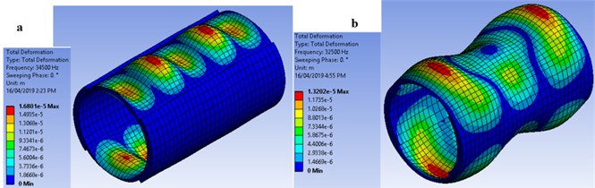
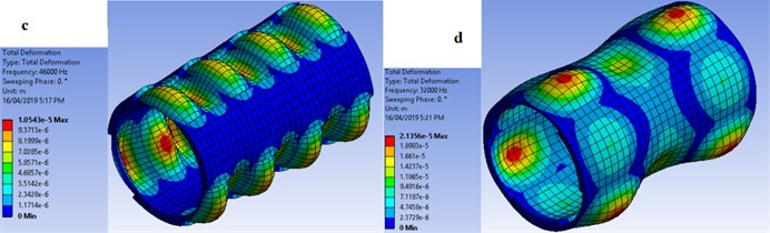
This means that although excitation of the intended mode shapes is feasible using stepped-thickness design, the maximum stress may exceed the material limit leading to the failure of the transducer in experimental tests. Therefore, alternatives might be sought. One alternative might be altering the thin region thickness. However, this may also alter the mode shapes and corresponding frequencies. The other alternative is to just reduce the excitation voltage as it does not change the mode shape, but it diminishes the vibration amplitude and accordingly reduces the maximum stress. To verify this, one simulation was performed for the specimen with two external circumferential steps at 18 V instead of initial 36 V. The maximum stress was reduced to 53 MPa from 106 MPa. This might be still high, however, it proves that depending on the material used and its stress limitations, the excitation voltage can be varied in such a way to keep the stress distribution within the safe range without altering the mode shape of vibration.
5. Conclusions
This work investigated the effectiveness of using stepped-thickness design for cylindrical piezoelectric shells to localize vibration amplitude and excite certain intended mode shapes of vibration. To this aim, FEA software, ANSYS was employed the reliability of which has been proven in the literature. Stress distribution as an important design consideration was also taken into account. The results revealed that using either internally or externally circumferential stepped-thickness design, it is possible to excite mode shapes with the same circumferential wave number as the number of steps. However, stress level may exceed the material limit. To tackle this issue, an alternative was proposed and validated by reducing the excitation voltage which does not affect the mode shape of vibration but reduces the vibration amplitude and accordingly stress level.
The stepped-thickness design can be considered for various size requirements for different applications. It is only needed to consider the requirements for the intended application to carefully design the required number of steps and the excitation voltage can then be easily adjusted to achieve a safe stress distribution.
References
-
Al Jumaily A.-M., Meshkinzar A. On the development of focused ultrasound liquid atomizers. Advances in Acoustics and Vibration, 2017, Vol. 2017, p. 7861726.
-
Gallego Juárez J.-A., Rodríguez Corral G., Gaete Garreton L. An ultrasonic transducer for high power applications in gases. Ultrasonics, Vol. 16, Issue 6, 1978, p. 267-271.
-
Barone A., Gallego Juarez J.-A. Flexural vibrating free-edge plates with stepped thicknesses for generating high directional ultrasonic radiation. The Journal of the Acoustical Society of America, Vol. 51, Issue 3, 1972, p. 953-959.
-
Espinosa F. M. D., Gallego Juárez J.-A. A directional single-element underwater acoustic projector. Ultrasonics, Vol. 24, Issue 2, 1986, p. 100-104.
-
Gallego Juárez J.-A., Rodríguez Corral G., Sarabia E.-R.-F.-D., Vázquez Martínez F., Acosta Aparicio V.-M., Campos Pozuelo C. Development of industrial models of high-power stepped-plate sonic and ultrasonic transducers for use in fluids. Ultrasonics Symposium, 2001.
-
Gallego Juarez J.-A., Rodriguez Corral G., Sarabia E.-R.-F.-D., Vazquez Martinez F., Campos Pozuelo C., Acosta Aparicio V.-M. Recent developments in vibrating-plate macrosonic transducers. Ultrasonics, Vol. 40, 2002, p. 889-893.
-
Gallego Juárez J.-A., Rodriguez G., Acosta Aparicio V.-M., Riera E., Cardoni A. Power ultrasonic transducers with vibrating plate radiators. Power Ultrasonics, Cambridge, 2014.
-
Wang H., Toda M. Curved PVDF airborne transducer. IEEE Transactions on Ultrasonics, Ferroelectrics, and Frequency Control, Vol. 46, Issue 6, 1999, p. 1375-1386.
-
Toda M., Tosima S. Theory of curved, clamped, piezoelectric film, air-borne transducers. IEEE Transactions on Ultrasonics, Ferroelectrics, and Frequency Control, Vol. 47, Issue 6, 2000, p. 1421-1431.
-
Toda M. Phase-matched air ultrasonic transducers using corrugated PVDF film with half wavelength depth. IEEE Transactions on Ultrasonics, Ferroelectrics, and Frequency Control, Vol. 48, Issue 6, 2001, p. 1568-1574.
-
Blum F., Jarzynski J., Jacobs L. J. A focused two-dimensional air-coupled ultrasonic array for non-contact generation. NDT & E International, Vol. 38, Issue 8, 2005, p. 634-642.
-
Garcia Perez J.-V., Carcel J. A., Fuente Blanco S.-D.-L., Sarabia E. R. F. D. Ultrasonic drying of foodstuff in a fluidized bed: parametric study. Ultrasonics, Vol. 44, 2006, p. 539-543.
-
Toda M., Thompson M. L. Contact-type vibration sensors using curved clamped PVDF film. IEEE Sensors Journal, Vol. 6, Issue 5, 2006, p. 1170-1177.
-
Toda M., Dahl J. PVDF corrugated transducer for ultrasonic ranging sensor. Sensors and Actuators A: Physical, Vol. 134, Issue 2, 2007, p. 427-435.
-
Bédard M., Berry A. Development of a directivity-controlled piezoelectric transducer for sound reproduction. Journal of Sound and Vibration, Vol. 311, Issues 3-5, 2008, p. 1271-1285.
-
Gallego-Juarez J.-A. Axisymmetric vibrations of circular plates with stepped thickness. Journal of Sound and Vibration, Vol. 26, Issue 3, 1973, p. 411-416.
-
Emeterio J. L. S., Gallego-Juarez J.-A., Rodriguez-Corral G. High axisymmetric modes of vibration of stepped circular plates. Journal of Sound and Vibration, Vol. 114, Issue 3, 1987, p. 495-505.
-
Al-Jumaily A.-M., Jameel K. Influence of the Poisson ratio on the natural frequencies of stepped-thickness circular plate. Journal of Sound and Vibration, Vol. 234, Issue 5, 2000, p. 881-894.
-
Darvizeh A., Darvizeh M., Ansari R., Meshkinzar A. Effect of low density, low strength polyurethane foam on the energy absorption characteristics of circumferentially grooved thick-walled circular tubes. Thin-Walled Structures, Vol. 71, 2013, p. 81-90.
-
Darvizeh A., Darvizeh M., Ansari R., Meshkinzar A. Analytical and experimental investigations into the controlled energy absorption characteristics of thick-walled tubes with circumferential grooves. Journal of Mechanical Science and Technology, Vol. 28, Issue 10, 2014, p. 4199-4212.
-
Darvizeh A., Meshkinzar A., Alitavoli M., Rajabiehfard R. Low velocity impact of empty and foam filled circumferentially grooved thick-walled circular tubes. Thin-Walled Structures, Vol. 110, 2017, p. 97-105.
-
Meshkinzar A., Al-Jumaily A.-M. Acoustic radiation of axially stepped-thickness piezoelectric cylindrical shells. ASME International Mechanical Engineering Congress and Exposition, Pittsburgh, Pennsylvania, USA, 2018.
-
Meshkinzar A., Al-Jumaily A.-M., Harris P. D. Acoustic amplification utilizing stepped-thickness piezoelectric circular cylindrical shells. Journal of Sound and Vibration, Vol. 437, 2018, p. 110-118.
-
Khalifa A. M. Exact solutions for the vibration of circumferentially stepped orthotropic circular cylindrical shells. Comptes Rendus Mécanique, Vol. 339, Issue 11, 2011, p. 708-718.
-
Berlincourt D., Cerran D., Jaffe H. Physical Acoustics. Piezoelectric and Piezomagnetic Materials and Their Function in Transducers. Academic Press, New York, 1964, p. 169-270.
-
ANSYS Meshing Application Introduction, Training Manual. ANSYS Inc, 2009.
-
Munz D., Fett T., Muller S., Thun G. Deformation and strength behaviour of a soft PZT ceramic. SPIE Conference on Mathematics and Control in Smart Structures, San Diego, California, 1998.
Cited by
About this article

