Abstract
A unified formulation for vibration analysis of coupled open cylindrical shell and annular sector plate system with general boundary and coupling conditions is presented in this study by using a modified Fourier-Ritz method. Under the framework, each of the displacements of the open cylindrical shell and the annular sector plate, regardless of boundary and coupling conditions, is expanded as a two-dimensional (2-D) Fourier cosine series supplemented with closed-form auxiliary functions introduced to remove the potential discontinuities at the junction and accelerate the convergence of the series expansion. Since the displacement fields are constructed adequately smooth throughout the entire solution domain, an exact solution is obtained based on the Rayleigh-Ritz procedure by using the energy functions of the coupled system. The arbitrary coupling position and included angle of the open cylindrical shell-annular sector plate structure considered in the theoretical formulation make the present method more general. The convergence and accuracy of the present method are tested and validated by a number of numerical examples for open cylindrical shell-annular sector plate structure with various boundary restraints and general elastic coupling conditions. Some new results are presented to provide useful information for future researchers.
1. Introduction
The coupled systems are widely used in practical engineering applications, such as submarines, aerospace and silos. Nowadays, the coupled system is frequently encountered and always subjected to the extreme environment and dynamic loads, and when the shell-plate combination becomes larger and thinner, its vibration problem becomes more and more complex. Thus, it is of great significance to understand thoroughly the vibration behavior of different structure combinations.
Because of the wide engineering applications of the shell-plate combination, its vibration problems have attracted considerable researcher’s interest and many methods for investigating their dynamical characteristics have been promoted. Huang and Soedel [1] presented the reacceptance method to solve the free vibration analysis of a simply-supported cylindrical shell coupled with a circular plate. The coupling position of the circular plate may be assigned at any arbitrary axial position. The two substructures were coupled together by the line receptances which were obtained by the responses of the circular plate and the cylindrical shell subjected to line force and line moment loadings along the interface. Then, Yim et al. [2] extended the method to a cylindrical shell attached with a circular plate. The boundary condition of the cylindrical shell is clamped-free and a beam function was utilized as the modal function of the shell while the circular plate was considered to be simply supported. Irie et al. [3] applied the transfer matrix technique to analyze the free vibration behavior of coupled conical- cylindrical shells. At the joint of the coupled system, the coupling conditions were achieved by using the transfer matrix while the equations of motion were derived with subject to each element of the structure matrix under the consideration of the boundary conditions. And then, Liang and Chen [4] adopted the transfer matrix method to analyze the vibration of a conical shell coupled with an annular end plate. Tavakoli and Singh [5] presented the state space method for the eigensolution of axisymmetric joined/hermetic thin shell structures. In the method, Padé approximation for the matrix exponentiation was used to solve the system of eight coupled first order differential equations for each shell component, which were further joined by matching all of the interface displacements and forces. Sivadas and Ganesan [6] used a higherorder semi-analytical finite element solution to analyze the free vibration behavior of combined shells including cylinder-cone, cylinder-plate and stiffened shells. And then, the semi-analytical finite element method was extended by Stanley and Ganesan [7] to investigate the free vibration of cylindrical shells coupled with a circular plate at arbitrary locations with the consideration of various classical boundary conditions. The free vibration of a cylindrical shell-circular plate combination with general coupling and various boundary conditions was achieved by Cheng and Nicolas [8] using the Rayleigh-Ritz method. The artificial stiffness-like spring system was adopted to simulate the elastic coupling between the cylindrical shell and the circular plate. Qu et al. [9-11] proposed a modified variational approach for the vibration analysis of ring-stiffened conical, cylindrical and spherical shell combinations. The shell combinations were divided into appropriate shell segments and all continuity constraints on segment interfaces were achieved by means of a modified variational principle and the least-squares weighted residual method. Lee et al. [12] developed the Rayleigh-Ritz method to analyze the vibration characteristics of the hemispheric-cylindrical shell combinations, in which the boundaries of the hemispheric shell component were assumed completely free whereas the cylindrical shell component was under simply-supported boundary conditions at the joints. Monterrubio [13] presented the penalty function method together with the Rayleigh-Ritz method for vibration analysis of shallow shells with classical boundary conditions. Ma et al. [14, 15] proposed an analytical method for vibration analysis of conical, cylindrical shell and annular plate combinations. The boundary force and coupling conditions of the shell-plate combinations were simulated by introducing the artificial stiffness-like spring system and the general elastic boundary and coupling conditions were achieved by assigning different values to the siffnesses of the boundary and coupling springs. An accurate solution was achieved from the modified Fourier series method together with the Rayleigh-Ritz method, in which the admissible functions of shells and plates were invariantly expressed as the modified Fourier series to remove the potential discontinuities at the junction and the extremes of the combinations.
From the review of the literature above, it appears that most of the previous studies on the shell-plate combinations are composed of close shells and annular plates with classical boundary conditions. However, the open shell coupled with the annular sector plate is widely used in practical engineering applications, such as aerospace crafts, naval vehicles and construction buildings. In addition, the boundary and coupling conditions of the coupled system is not always classical and rigid coupling in nature, and a variety of possible boundary restraining cases including classical boundary conditions, elastic boundary restraints, elastic coupling restraints, and their combinations may be encountered. To the best of authors’ knowledge, there are no reported solutions on the dynamic analysis of open cylindrical shells coupled with annular sector plates with arbitrary boundary and coupling conditions in the literature. Hence, it is necessary and of great significance to develop a unified solution which is capable of universally dealing with the coupled open cylindrical shell and annular sector plate systems subjected to general boundary and coupling conditions.
Recently, a modified Fourier series technique proposed by Li [16, 17] has been widely used in the vibration analysis of plates, shells and coupled systems with general boundary and coupling conditions by the Rayleigh-Ritz method, e.g., [18-29]. Therefore, the present work can be considered as an extension of the method and attempts to provide a unified solution method for the free vibration analysis of open shell coupled with the annular sector plate with general boundary and coupling conditions. Under the current framework, the modified Fourier series method together with the Rayleigh-Ritz procedure and the artificial spring technique are adopted to derive the theoretical formulation. The general boundary and coupling conditions of the plates are realized by applying the artificial spring boundary and coupling technique. The displacement fields of each substructure, regardless of the boundary and coupling conditions, are expressed as a modified Fourier series which is constructed as the linear superposition of a standard Fourier cosine series supplemented with auxiliary polynomial functions introduced to eliminate all the relevant discontinuities with the displacement and its derivatives at the edges and accelerate the convergence of series representations. Since the displacement fields are constructed adequately smooth throughout the entire solution domain, an exact solution is obtained based on the Rayleigh-Ritz procedure by the energy functions of the coupled system. The excellent accuracy and reliability of the current solutions are confirmed by comparing the present results with those from ABAQUS. The effects of the coupling position, included angle of the open cylindrical shell-annular sector plate structures and elastic coupling conditions on the vibration behavior of the coupled system are also investigated. Some new results are presented to provide useful information for future researchers.
2. Theoretical formulations
2.1. System description
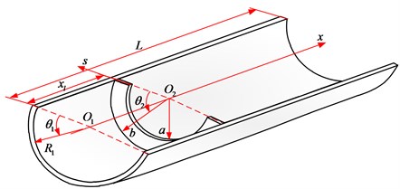
The geometry and coordinate system for the open cylindrical shell-annular sector plate structure are depicted in Fig. 1. The physical dimensions and a cylindrical coordinate system of the open cylindrical shell under consideration are shown in Fig. 1. The dimensions of the open cylindrical shell include the thickness , circumferential included angles , length and radius . The annular sector plate with thickness , sector angle , inner radius , outer radius and width () is described in the cylindrical coordinate system . A local cylindrical coordinate system is also shown in the Fig. 1, which will be used in the analysis, in which s is measured from the inner edge in the radial direction. Thus, and are the meridional directions respectively for the annular sector plate and the open cylindrical shell component. It is noted that a special case will be encountered when the inner radius of the annular sector plate equals to 0, and the annular sector plate degenerates to a circular sector plate which is also extensively employed in engineering applications. , and are introduced as the deformations of the annular sector plate in , , directions, respectively. , and are represented as the deformations of the open cylindrical shell in , , directions, respectively. The thicknesses of both the open cylindrical shell and the annular sector plate ( and ) are assumed to be uniform and very small compared with the other parameters so that the thin plate and shell theories are applicable.
Fig. 1Co-ordinate system and notation for the coupled open cylindrical shell-annular sector plate structure
2.2. Energy expressions of the annular sector plate
According to the thin plate theory (Leissa, 1973), the strain-displacement relations of the annular sector plate in local cylindrical coordinate system with the consideration of both in-plane and out-plane vibration can be described as:
where , and are the normal and shear strains in the middle surface of the annular sector plate, and are the mid-surface changes in curvature and is the mid-surface twist.
Thus, the strain energy and the kinetic energy of the annular sector plate can be written as:
where , and denote the Young’s modulus, the mass density and the Poisson’s ratio of the annular sector plate, respectively.
Substituting Eq. (1-6) into Eq. (7) and (8), the strain energy and kinetic energy expression of the annular sector plate can be written in terms of the middle plane displacements and rotations:
2.3. Energy expressions of the open cylindrical shell
According to the Kirchhoff-Love hypothesis and the Qatu’s formulation, the middle surface strains and curvature changes of the considered open cylindrical shell can be written in terms of the displacements components as:
where , and indicate the strains in the middle surface; , and are the curvature changes;
The liner strains in the space of the open shell are defined as:
According to the general Hooke’s law, the corresponding stresses are obtained as follows:
in which and are the normal stresses, and is the shear stress. (, 1, 2, 6) are the constants relating stresses with strains, and for an open cylindrical shell made from isotropic material, they are defined as:
where and are the Young’s moduli and the Poisson’s ratio, respectively. By carrying the integration of stresses over the cross-section and integrating the moments of the in-plane stresses over the thickness, the force and moment resultants related to the strains in the middle surface and curvature changes are defined as:
in which , and are the normal and shear force resultants. , and represent the bending and twisting moment resultants. and are the stretching and bending stiffness coefficients, which are defined as:
The strain energy and kinetic energy expressions of an open cylindrical shell are defined as:
Substituting Eq. (11-22) into Eq. (24) and (25), the strain energy and kinetic energy expressions of the open cylindrical shell can be written in terms of the middle plane displacements and rotations as follows:
2.4. Arbitrary boundary conditions and coupling conditions
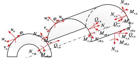
In this study, the artificial stiffness spring technique is adopted to simulate the arbitrary boundary conditions and continuity conditions based on the Rayleigh-Ritz energy method. With this method, both the boundary conditions and the continuity conditions of the open cylindrical shell-annular sector plate structure are described by the potential energy stored in the employed springs. The force and moment resultants at boundaries of the open cylindrical shell and the annular sector plate are depicted in Fig. 2, , , and are the in-plane forces, and are the transverse shear forces, and are the bending moments and and denote the twisting moments respectively.
Fig. 2Force and moment resultants of the open cylindrical shell and annular sector plate
The boundary and coupling conditions are determined by restrains of forces and moments at the boundaries and interface. In this study, artificial stiffness spring systems are used at the boundaries and interface of the plate-shell combination to constrain these forces and moments. Under the framework, the general elastic boundary conditions of the open cylindrical shell component can be expressed as:
And the general elastic boundary conditions at the boundary edges of the annular sector plate can be written as:
With the consideration of the relative position of the annular sector plate coupling to the open cylindrical shell component, the general elastic continuity and equilibrium conditions at the interface can be expressed as:
where , , and represent the stiffnesses of the connective springs and , , and are the stiffnesses of linear springs in , and directions and rotational springs around direction and the subscripts , , and represent the springs at the boundary edges of the cylindrical shell respectively. , , , respectively, denote the stiffnesses of the springs employed at the boundary edges of the annular sector plate and the subscripts , and represent the locations of the springs, is the axial position of the annular sector plate relative to the open cylindrical shell.
For two special cases 0 and 0, i.e. the annular sector plate is arranged at one end of the open cylindrical shell component and the annular sector plate degenerates to be a circular sector plate, when the stiffnesses of corresponding springs used at the coupled boundary and the inner radius of the annular sector plate are revalued to be zero automatically. From the mathematical expressions of continuity conditions and boundary conditions as shown above, all of the force and moment resultants of the two sub-structures at the interface are constrained by the artificial stiffness spring technique. Therefore, the arbitrary boundary and continuity conditions can be conveniently achieved by varying the stiffnesses of corresponding springs. Especially for the classical boundary conditions, the related springs’ stiffnesses will be set to be infinite (extremely large) or zero. Thus, the potential energy stored in the boundary and connective springs can be written as:
2.5. Admissible displacement functions and solution procedure
The modified Fourier series method adopted in the study may certainly facilitate the task. The improved Fourier series consists of a standard Fourier cosine series and several auxiliary functions. Here, the introduction of the auxiliary functions is to remove the discontinuities potentially exhibited by the original displacement functions and their derivatives. And it can also accelerate the convergence of the representations at the same time. Thus, the detailed expressions of the displacements of the annular sector plate (, , ) and the open cylindrical shell component (, , ) can be written as:
where is the angular frequency, denotes time, , , , and , , , , , are the Fourier coefficients of two-dimensional Fourier series expansions for the displacement functions, respectively. , , , , , ,, , , , , are the supplemented coefficients of the auxiliary functions. All of them need to be determined in future.
As mentioned earlier, the main purpose of introducing these supplementary terms into the Fourier series is to remove any potential discontinuities of the original displacements and their derivatives throughout the entire structure including the boundaries and then to effectively enhance the convergence of the results. As indicated by energy expressions, the second order derivatives for the radial displacements and the first order derivatives for the in-plane displacements should exist to guarantee the continuity of displacements and corresponding derivatives at any point on the coupled open cylindrical shell-annular sector plate structure, thus, it is required that at least two-order derivatives of the admissible functions exist and are continuous at any point on the structure. Such requirements can be readily satisfied by choosing simple auxiliary functions as follows:
It is easy to verify that:
Once the admissible displacement functions and energy functions of the open cylindrical shell-annular sector plate structure are established, the remaining task is to determine the coefficients of the admissible functions. The Lagrangian for the open cylindrical shell-annular sector plate can be eventually expressed as:
Substituting Eqs. (9), (10), (26), (27), and (38-45) into Eq. (61) and performing the Rayleigh-Ritz procedure with respect to each unknown coefficient, the equations of motion for the open cylindrical shell-annular sector plate structure can be yielded and are given in the matrix form:
where and are the stiffness and mass matrices of the coupling structure, is the coefficient vector and they can be written as:
where and are the truncated number for and respectively. By solving the Eq. (62), the frequencies (or eigenvalues) of the coupled open cylindrical shell-annular sector plate structure can be readily obtained and the mode shapes can be yielded by substituting the corresponding eigenvectors into the series representations of displacement components.
3. Numerical results and discussion
The convergence, accuracy and versatility of the present method for vibration analysis of the coupled open cylindrical shell-annular sector plate structure will be examined by a number of numerical examples. The effects of elastic boundary restraints, elastic coupling restraints and dimensional parameters on the vibration behavior of the coupling structure are also investigated. For conveniently referring to the classical boundary conditions, F, S and C denote respectively free, simply-supported and clamped restraints. Unless otherwise stated, the geometric and material parameters are uniformly arranged as 2.0×10¹¹ Pa, 0.3, 7800 kg/m3, , 0.01 m, 0.5 m, 1 m, 3 m, 1 m. In order to generalize the results for the other approaches as reference, non-dimensional frequency parameter is introduced here.
3.1. Convergence and validation study
Convergence study of the first eight frequency parameters for the open cylindrical shell-annular sector plate structure is carried out to determine the optimal number of numerically truncated finite number of terms required for satisfactory solutions, as shown in Table 1. The plate component is located with the end of the shell component and the boundary conditions of the plate and shell are all free and clamped. It is obvious that the frequency parameters converge monotonically as the truncated numbers increase. Therefore, in the following calculations, all the Fourier series truncated numbers are truncated into 14. To further validate the accuracy and reliability of the current solution, more numerical examples will be presented.
To validate the applicability of the present method for open cylindrical shell-annular sector plate structure with arbitrary boundary and coupling conditions, a number of examples for the free vibration analysis of the coupled system by the present method and the ABAQUS solution (because of lacking of the existing literature results) with the consideration of various boundary and coupling conditions, are conducted in the next examples. In these models, the type of elements used for the ABAQUS is the CPS4R and the numbers of elements for the annular sector plate and open cylindrical shell are respectively 5000 and 15000. Table 2 shows the natural frequencies of open cylindrical shell-annular sector plate structure with classical boundary conditions. A good agreement can be observed. Table 3 shows the natural frequencies of the open cylindrical shell-annular sector plate structure with one edge elastically restrained at and the rest of boundaries set to clamped restraints. The little disparity between the results by the present method and the ABAQUS program validates the accuracy of the present method for general elastic boundary conditions.
Table 1Convergence of the coupled structures of open cylindrical shell-annular sector plate structure with complete clamped and free boundary conditions
B.C | Mode number | ||||||||
1 | 2 | 3 | 4 | 5 | 6 | 7 | 8 | ||
CCC-CCC (All-clamped) | 12 | 0.2410 | 0.2765 | 0.3012 | 0.3609 | 0.3781 | 0.4278 | 0.4533 | 0.4916 |
13 | 0.2410 | 0.2765 | 0.3012 | 0.3608 | 0.3781 | 0.4277 | 0.4533 | 0.4916 | |
14 | 0.2410 | 0.2765 | 0.3012 | 0.3608 | 0.3781 | 0.4277 | 0.4533 | 0.4916 | |
15 | 0.2410 | 0.2765 | 0.3012 | 0.3608 | 0.3781 | 0.4277 | 0.4533 | 0.4916 | |
16 | 0.2410 | 0.2765 | 0.3012 | 0.3608 | 0.3781 | 0.4276 | 0.4533 | 0.4916 | |
FFF-FFF (All-free) | 12 | 0.0156 | 0.0429 | 0.0593 | 0.0594 | 0.0748 | 0.0925 | 0.1175 | 0.1313 |
13 | 0.0156 | 0.0429 | 0.0593 | 0.0594 | 0.0748 | 0.0925 | 0.1175 | 0.1312 | |
14 | 0.0156 | 0.0429 | 0.0593 | 0.0594 | 0.0748 | 0.0925 | 0.1175 | 0.1312 | |
15 | 0.0156 | 0.0429 | 0.0593 | 0.0594 | 0.0748 | 0.0924 | 0.1175 | 0.1312 | |
16 | 0.0156 | 0.0429 | 0.0593 | 0.0594 | 0.0748 | 0.0924 | 0.1175 | 0.1312 | |
Table 2Variation of frequency parameters Ω of open cylindrical shell- annular sector plate structure with classical boundary conditions
Location | Mode | All-free | All-clamped | All- simply-supported | ||||||
Present | ABAQUS | Err (%) | Present | ABAQUS | Err (%) | Present | ABAQUS | Err (%) | ||
0 | 1 | 0.0081 | 0.0082 | 0.65 | 0.1470 | 0.1469 | 0.07 | 0.0743 | 0.0744 | 0.08 |
2 | 0.0255 | 0.0254 | 0.15 | 0.1660 | 0.1659 | 0.06 | 0.1066 | 0.1065 | 0.07 | |
3 | 0.0371 | 0.0372 | 0.13 | 0.2179 | 0.2177 | 0.08 | 0.1518 | 0.1518 | 0.02 | |
4 | 0.0443 | 0.0442 | 0.26 | 0.2306 | 0.2304 | 0.07 | 0.1720 | 0.1723 | 0.15 | |
5 | 0.0473 | 0.0474 | 0.37 | 0.2452 | 0.2444 | 0.31 | 0.1808 | 0.1824 | 0.87 | |
6 | 0.0698 | 0.0698 | 0.00 | 0.2614 | 0.2613 | 0.04 | 0.1844 | 0.1847 | 0.19 | |
1 | 0.0093 | 0.0093 | 0.21 | 0.2293 | 0.2293 | 0.03 | 0.1522 | 0.1521 | 0.05 | |
2 | 0.0292 | 0.0290 | 0.66 | 0.2389 | 0.2387 | 0.09 | 0.1758 | 0.1759 | 0.10 | |
3 | 0.0347 | 0.0347 | 0.10 | 0.2443 | 0.2427 | 0.67 | 0.1993 | 0.1991 | 0.11 | |
4 | 0.0508 | 0.0510 | 0.28 | 0.2517 | 0.2501 | 0.62 | 0.2029 | 0.2034 | 0.24 | |
5 | 0.0726 | 0.0725 | 0.20 | 0.2681 | 0.2689 | 0.28 | 0.2059 | 0.2058 | 0.09 | |
6 | 0.0846 | 0.0844 | 0.20 | 0.3198 | 0.3188 | 0.31 | 0.2125 | 0.2131 | 0.27 | |
Table 3Frequency parameters Ω of open cylindrical shell-annular sector plate structure with elastic boundary conditions
Location | Mode | 106 | 109 | 1016(clamped) | ||||||
Present | ABAQUS | Err (%) | Present | ABAQUS | Err (%) | Present | ABAQUS | Err (%) | ||
0 | 1 | 0.1033 | 0.1034 | 0.06 | 0.1417 | 0.1421 | 0.34 | 0.1470 | 0.1469 | 0.07 |
2 | 0.1268 | 0.1271 | 0.26 | 0.1532 | 0.1534 | 0.11 | 0.1660 | 0.1659 | 0.06 | |
3 | 0.1584 | 0.1581 | 0.20 | 0.2085 | 0.2085 | 0.03 | 0.2179 | 0.2177 | 0.08 | |
4 | 0.1919 | 0.1919 | 0.00 | 0.2241 | 0.2251 | 0.45 | 0.2306 | 0.2304 | 0.07 | |
5 | 0.2326 | 0.2343 | 0.72 | 0.2450 | 0.2455 | 0.20 | 0.2452 | 0.2444 | 0.31 | |
6 | 0.2382 | 0.2385 | 0.16 | 0.2523 | 0.2539 | 0.62 | 0.2614 | 0.2613 | 0.04 | |
1 | 0.1402 | 0.1394 | 0.54 | 0.2147 | 0.2141 | 0.26 | 0.2293 | 0.2293 | 0.03 | |
2 | 0.1623 | 0.1607 | 0.96 | 0.2291 | 0.2296 | 0.23 | 0.2389 | 0.2387 | 0.09 | |
3 | 0.2370 | 0.2374 | 0.15 | 0.2401 | 0.2392 | 0.34 | 0.2443 | 0.2427 | 0.67 | |
4 | 0.2440 | 0.2454 | 0.60 | 0.2474 | 0.2481 | 0.28 | 0.2517 | 0.2501 | 0.62 | |
5 | 0.2612 | 0.2613 | 0.05 | 0.2702 | 0.2678 | 0.86 | 0.2681 | 0.2689 | 0.28 | |
6 | 0.2699 | 0.2700 | 0.03 | 0.3259 | 0.3239 | 0.61 | 0.3198 | 0.3188 | 0.31 | |
The natural frequencies of the open cylindrical shell-annular sector plate structure with elastic coupling conditions on the basis of elastic boundary conditions are given in Table 4. From the table a consistent agreement of present results with the referential data is seen. The discrepancy is very small and doesn’t exceed 0.96 % for the worst case. The results convincingly demonstrate that the present method is accurate and reliable to solve the open cylindrical shell-annular sector plate structure with general elastic boundary and coupling conditions.
Table 4Frequency parameters Ω of open cylindrical shell-annular sector plate with elastic coupling conditions
Location | Mode | 106 | 109 | 1016 (rigidly) | ||||||
Present | ABAQUS | Err (%) | Present | ABAQUS | Err (%) | Present | ABAQUS | Err (%) | ||
0 | 1 | 0.0675 | 0.0676 | 0.17 | 0.0993 | 0.0994 | 0.04 | 0.1033 | 0.1034 | 0.06 |
2 | 0.0855 | 0.0851 | 0.41 | 0.1268 | 0.1274 | 0.44 | 0.1268 | 0.1271 | 0.26 | |
3 | 0.1257 | 0.1263 | 0.46 | 0.1573 | 0.1577 | 0.26 | 0.1584 | 0.1581 | 0.20 | |
4 | 0.1283 | 0.1281 | 0.15 | 0.1893 | 0.1901 | 0.40 | 0.1919 | 0.1919 | 0.00 | |
5 | 0.1300 | 0.1305 | 0.35 | 0.2313 | 0.2330 | 0.77 | 0.2326 | 0.2343 | 0.72 | |
6 | 0.1606 | 0.1611 | 0.31 | 0.2336 | 0.2339 | 0.15 | 0.2382 | 0.2385 | 0.16 | |
1 | 0.0875 | 0.0876 | 0.18 | 0.1399 | 0.1401 | 0.19 | 0.1402 | 0.1394 | 0.54 | |
2 | 0.1130 | 0.1131 | 0.14 | 0.1577 | 0.1564 | 0.83 | 0.1623 | 0.1607 | 0.96 | |
3 | 0.1297 | 0.1303 | 0.41 | 0.2341 | 0.2330 | 0.49 | 0.2370 | 0.2374 | 0.15 | |
4 | 0.1308 | 0.1307 | 0.08 | 0.2419 | 0.2417 | 0.05 | 0.2440 | 0.2454 | 0.60 | |
5 | 0.1676 | 0.1680 | 0.27 | 0.2563 | 0.2559 | 0.14 | 0.2612 | 0.2613 | 0.05 | |
6 | 0.2003 | 0.2013 | 0.49 | 0.2693 | 0.2689 | 0.14 | 0.2699 | 0.2700 | 0.03 | |
From the above examples about the general elastic boundary and coupling conditions, it is noted that the frequency parameters increase when the stiffness of the boundary and coupling springs increases. In addition, the classical boundary conditions can be readily achieved by simply setting the stiffness of the entire springs to be zero or infinitely large. However, the ‘infinitely large’ is represented by a sufficiently large number in actual calculations. Thus, the effects of the restraint stiffness of boundary and coupling springs on the modal characteristics should be investigated. For simplicity and convenience in the analysis, in the case of boundary springs, the entire boundary springs are set to vary uniformly at and the coupling conditions are all rigid conditions; in the case of coupling springs, the entire coupling springs vary at the coupled location and the boundary conditions are all clamped boundary conditions. Variations of the lowest three frequency parameters versus the elastic boundary restraint parameters for the open cylindrical shell coupled with the annular sector plate with two types of coupled locations are shown in Fig. 3. In Fig. 3(a), it is shown that the frequency parameter almost stays unchanged when the stiffness of boundary springs is larger than 1011 or smaller than 106. In Fig. 3(b), it is obvious that the frequency curve changes greatly within the stiffness range from 106 to 1011. Thus, it can be found that the variations of the vibration characteristic of the open cylindrical shell-annular sector plate structure have similar tendency, regardless of the location of the coupling. It can also be easily seen that the frequency parameters exhibit the large change as the boundary stiffness parameters increase in a certain range.
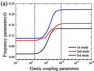
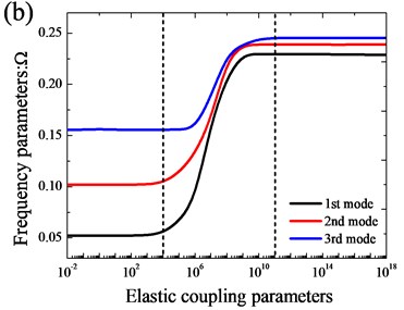
In Fig. 4, the variation of the frequency parameters versus the elastic coupling parameters for open cylindrical shell with annular sector plate with two coupled styles is shown. From the Fig. 4, we can see the similar phenomenon with the variation of boundary stiffness parameters except the variation region of the elastic coupling parameters. Based on the analysis, the ‘infinitely large’ of the boundary and coupling springs achieved by setting the spring stiffnesses equal to 1014 and 1012 is appropriate in actual calculations.
Through the above analysis, it implies that the present method is able to make correct predictions for the modal characteristics of the open cylindrical shell-annular sector plate structure with not only classical boundary and rigid coupling conditions but also elastically restraint boundary and coupling conditions.
Fig. 3Variation of the frequency parameters Ω versus the elastic restraint parameters for open cylindrical shell with annular sector plate: a) xa= 0; b) xa=L1/2
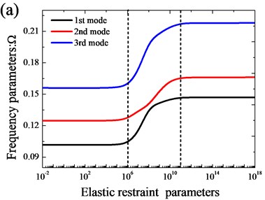
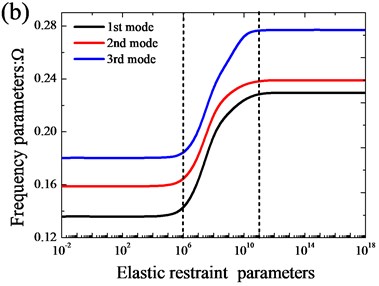
Fig. 4Variation of the frequency parameters Ω versus the elastic coupling parameters for open cylindrical shell with annular sector plate: a) xa= 0; b) xa=L1/2
3.2. Effects of the coupling position and included angles
The annular sector plate is not always located at the end or the middle of the open cylindrical shell and the included angle of the structure is arbitrary in practical engineering applications. In the theoretical formulations, the arbitrary coupling position of the annular sector plate coupled with the open cylindrical shell and the arbitrary included angle of the coupled system are considered in present method. The effects of the coupling position of the annular sector plate and arbitrary included angle of the coupled system on the vibration behavior of the coupled structure will be investigated in this sub-section.
The variations of the frequency parameters versus the included angles for an annular sector plate located at the end and the middle of the open cylindrical shell are given in Fig. 5(a) and Fig. 5(b), respectively. Form the Fig. 5, it is observed that the frequency parameters decrease rapidly from 5° to 120°, and beyond this range, the frequency parameters almost stay unchanged. It means that the included angles have a great influence on the vibration behavior of the open cylindrical shell-annular sector plate structure in the lower included angles region (from 5° to 120°), and have few effects when the included angles are out of that region.
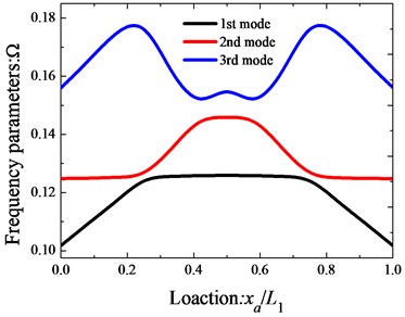
Fig. 6 depicts the variations of the 1st, the 3rd and the 6th non-dimensional natural frequency parameters versus the coupling position of the annular sector plates for the open cylindrical shell-annular sector plate structure with all clamped boundary conditions. Obviously, the coupling position of the annular sector plates has a great influence on the vibration behavior of the open cylindrical shell-annular sector plate structure. Many interesting characteristics can be observed from the figure. Firstly, the figure is symmetrical about ; Secondly, there is little variation in the lowest frequency parameters of the open cylindrical shell-annular sector plate structure as the coupling position increases from 0 to . For case of the 1st mode, the frequency parameters first go up and then almost stay unchanged with the coupling position increasing. For case of the 2nd mode, the frequency parameters keep unchanged first, then increase, and finally may reach its crest around . As to the case of the 3rd mode, the frequency parameters first increase rapidly until , then decline rapidly from to , and last, the frequency parameters climb up slowly.
Fig. 5Variation of the frequency parameters Ω versus the included angles for open cylindrical shell with annular sector plate: a) xa= 0; b) xa=L1/2
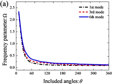
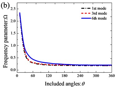
Fig. 6Variation of the frequency parameters Ω versus the coupling locations of the annular sector plate
Based on the above discussion, the results of the open cylindrical shells coupled with annular sector plates with general boundary and coupling conditions can be served as the benchmark solution for the future computing methods. In addition, the parameter study can provide some useful results to the designers and engineers to avoid the unpleasant, inefficient and structurally damaging resonant in the design process.
4. Conclusions
In this paper, a modified Fourier-Ritz approach for free vibration analysis of coupled open cylindrical shell and annular sector plate systems with general boundary and coupling conditions is proposed. Under the framework, regardless of the boundary and continuity conditions, each displacement for the open cylindrical shell and the annular sector plate is invariantly expressed as the modified Fourier series composed of the standard Fourier series and auxiliary functions. The introduction of the auxiliary functions not only removes the potential discontinuities at the junction and the extremes of the combination but also accelerates the convergence of the series expansions. The general elastic boundary and coupling conditions of the combination are achieved by the potential energy stored in the artificial spring system. All the expansion coefficients are determined by the Rayleigh-Ritz method as the generalized coordinates. The convergence, accuracy and reliability of the present method are validated by the comparison of natural frequencies with ABAQUS solution for the open cylindrical shell-annular sector plate structures with various boundary conditions and general elastic coupling conditions. The coupling position of the annular sector plate and the included angle of the open cylindrical shell-annular sector plate structures have a great influence on the vibration behavior of the coupled system, which has been investigated in the study to provide helpful reference in engineering structural design.
References
-
Huang D., Soedel W. Natural frequencies and modes of a circular plate welded to a circular cylindrical shell at arbitrary axial positions. Journal of Sound and Vibration, Vol. 162, Issue 3, 1993, p. 403-427.
-
Yim J., Sohn D., Lee Y. Free vibration of clamped–free circular cylindrical shell with a plate attached at an arbitrary axial position. Journal of Sound and Vibration, Vol. 213, Issue 1, 1998, p. 75-88.
-
Irie T., Yamada G., Muramoto Y. Free vibration of joined conical-cylindrical shells. Journal of Sound and Vibration, Vol. 95, Issue 1, 1984, p. 31-39.
-
Liang S., Chen H. The natural vibration of a conical shell with an annular end plate. Journal of Sound and Vibration, Vol. 294, Issue 4, 2006, p. 927-943.
-
Tavakoli M., Singh R. Eigensolutions of joined/hermetic shell structures using the state space method. Journal of Sound and Vibration, Vol. 130, Issue 1, 1989, p. 97-123.
-
Sivadas K., Ganesan N. Free vibration analysis of combined and stiffened shells. Computers and Structures, Vol. 46, Issue 3, 1993, p. 537-546.
-
Stanley A. J., Ganesan N. Frequency response of shell-plate combinations. Computers and Structures, Vol. 59, Issue 6, 1996, p. 1083-1094.
-
Cheng L., Nicolas J. Free vibration analysis of a cylindrical shell-circular plate system with general coupling and various boundary conditions. Journal of Sound and Vibration, Vol. 155, Issue 2, 1992, p. 231-247.
-
Qu Y., Chen Y., Long X., Hua H., Meng G. A variational method for free vibration analysis of joined cylindrical-conical shells. Journal of Vibration and Control, 2012, p. 1077546312456227.
-
Qu Y., Chen Y., Long X., Hua H., Meng G. A modified variational approach for vibration analysis of ring-stiffened conical-cylindrical shell combinations. European Journal of Mechanics – A/Solids, Vol. 37, 2013, p. 200-215.
-
Qu Y., Wu S., Chen Y., Hua H. Vibration analysis of ring-stiffened conical-cylindrical-spherical shells based on a modified variational approach. International Journal of Mechanical Sciences, Vol. 69, 2013, p. 72-84.
-
Lee Y. S., Yang M. S., Kim H. S., Kim J. H. A study on the free vibration of the joined cylindrical-spherical shell structures. Computers and Structures, Vol. 80, Issue 27, 2002, p. 2405-2414.
-
Monterrubio L. E. Free vibration of shallow shells using the Rayleigh-Ritz method and penalty parameters. Proceedings of the Institution of Mechanical Engineers, Part C: Journal of Mechanical Engineering Science, Vol. 223, Issue 10, 2009, p. 2263-2272.
-
Ma X., Jin G., Shi S., Ye T., Liu Z. An analytical method for vibration analysis of cylindrical shells coupled with annular plate under general elastic boundary and coupling conditions. Journal of Vibration and Control, 2015, p. 1077546315576301.
-
Ma X., Jin G., Xiong Y., Liu Z. Free and forced vibration analysis of coupled conical-cylindrical shells with arbitrary boundary conditions. International Journal of Mechanical Sciences, Vol. 88, 2014, p. 122-137.
-
Li W. L. Free vibrations of beams with general boundary conditions. Journal of Sound and Vibration, Vol. 237, Issue 4, 2000, p. 709-725.
-
Li W. L. Comparison of Fourier sine and cosine series expansions for beams with arbitrary boundary conditions. Journal of Sound and Vibration, Vol. 255, Issue 1, 2002, p. 185-194.
-
Jin G., Ye T., Ma X., Chen Y., Su Z., Xie X. A unified approach for the vibration analysis of moderately thick composite laminated cylindrical shells with arbitrary boundary conditions. International Journal of Mechanical Sciences, Vol. 75, 2013, p. 357-376.
-
Chen Y., Jin G., Liu Z. Flexural and in-plane vibration analysis of elastically restrained thin rectangular plate with cutout using Chebyshev-Lagrangian method. International Journal of Mechanical Sciences, Vol. 89, 2014, p. 264-278.
-
Jin G., Ma X., Shi S., Ye T., Liu Z. A modified Fourier series solution for vibration analysis of truncated conical shells with general boundary conditions. Applied Acoustics, Vol. 85, 2014, p. 82-96.
-
Jin G. Ye T., Jia X., Gao S. A general Fourier solution for the vibration analysis of composite laminated structure elements of revolution with general elastic restraints. Composite Structures, Vol. 109, 2014, p. 150-168.
-
Chen Y., Jin G., Du J., Liu Z. Power transmission analysis of coupled rectangular plates with elastically restrained coupling edge including in-plane vibration. Proceedings of the Sydney, 2010.
-
Chen Y., Jin G., Liu Z. Free vibration analysis of circular cylindrical shell with non-uniform elastic boundary constraints. International Journal of Mechanical Sciences, Vol. 74, 2013, p. 120-132.
-
Wang Q., Shi D., Liang Q. Free vibration analysis of axially loaded laminated composite beams with general boundary conditions by using a modified Fourier-Ritz approach. Journal of Composite Materials, 2015, p. 0021998315602138.
-
Wang Q., Shi D., Liang Q., Shi X. A unified solution for vibration analysis of functionally graded circular, annular and sector plates with general boundary conditions. Composites Part B: Engineering, Vol. 88, 2016, p. 264-294.
-
Wang Q., Shi D., Shi X. A modified solution for the free vibration analysis of moderately thick orthotropic rectangular plates with general boundary conditions, internal line supports and resting on elastic foundation. Meccanica, p. 1-33.
-
Shi D., Wang Q., Shi X., Pang F. Free vibration analysis of moderately thick rectangular plates with variable thickness and arbitrary boundary conditions. Shock and Vibration, 2014.
-
Shi D., Wang Q., Shi X., Pang F. An accurate solution method for the vibration analysis of Timoshenko beams with general elastic supports. Proceedings of the Institution of Mechanical Engineers, Part C: Journal of Mechanical Engineering Science, 2014, p. 0954406214558675.
-
Shi D., Wang Q., Shi X., Pang F. A series solution for the in-plane vibration analysis of orthotropic rectangular plates with non-uniform elastic boundary constraints and internal line supports. Archive of Applied Mechanics, Vol. 85, Issue 1, 2015, p. 51-73.
About this article

The work reported in this paper is supported by the National Natural Science Foundation of China (No. 60834005), National Nature Science Foundation of Shandong Province of China and QingDao Science and Technology Plan Projects under Funds of ZR2013CL021 and 14-2-3-54-nsh respectively.
