Abstract
The vibrations of circular, annular and sector plates are different boundary value problems due to different edge conditions and thus have been treated separately using different solution algorithms and procedures. In this paper, a unified method is proposed for vibration analysis of moderately thick annular, circular plates and their sector counterparts with arbitrary boundary conditions. The unification of these plates is physically achieved by applying the coupling spring’s technique at the radial edges to ensure appropriate continuity conditions. Irrespective of the shape of the plate and the type of boundary conditions, each of the displacement function is expressed as a new form of trigonometric expansion with high convergence rate. Unlike most of the previous studies the current method can be universally applied to a wide range of vibration problems involving different shapes, boundary conditions, varying materials and geometric properties without modifying the solution algorithms and procedure. Furthermore, the current method can easily be applied to sector plates with an arbitrary inclusion angle of 2. The accuracy, reliability and versatility of the proposed method are fully demonstrated with several numerical examples for different shapes of plates and under different boundary conditions.
1. Introduction
Circular, annular and their sectorial counterparts are important structural components widely used in many engineering fields like civil, mechanical and marine engineering. As far as previous literature is concerned different solution algorithms and procedures have been adopted to study their vibration characteristics. The main reason behind these different solution algorithms and procedures was difference in their geometries resulting in different edge conditions.
A lot of research work has been done to study their dynamic characteristics under different boundary conditions. The important and comprehensive review on this subject can be found in Leissa’s 1973 book. The initial study on vibrations of circular plates or disks was done by Deresiewicz and Mindlin [1]. Employing the classical thin plate theory and Mindlin plate theory, these two researchers studied the vibration characteristics of axially symmetric circular disks. This work was further extended by Soni et al. [2] to axisymmetric orthotropic non uniform circular discs. They carried out their research using the same Mindlin plate theory and Chebyshev collocation technique. This technique was later employed by Gupta et al. to polar orthotropic annular Mindlin plates with non-uniform thickness [3]. Using Finite Element Method and three-dimensional finite strip model, Cheung et.al studied the vibration characteristics of thick and thin sector plates subjected to different types of classical boundary conditions [4, 5]. Investigation on vibration characteristics of annular sector plates having internal radial line and circumferential arc supports was carried out by Xiang et al. [6-7]. In another study Xiang et al. used first order shear deformation theory and studied the vibration response of thick circular and annular plates with internal ring stiffeners [8]. Later he extended his research to stepped circular Mindlin plates by employing domain decomposition technique to study the vibration characteristics [9]. Another similar study was performed by B. Singh and S. M. Hassan [10]. They studied the out of plane vibrations of a circular plate with different thickness variation. They approximated the thickness polynomial by interpolating the sample points along the thickness of the plate. In another study a combination of Rayleigh-Ritz method and Lagrange multiplier method was developed by S. Kitipornchai et al. to study the vibration characteristics of arbitrary shaped plates with corner supports [11]. Exact solution for annular sector plates subjected to simply supported radial edge conditions and general boundary conditions at circular edges was obtained by McGee et al. [12] employing the Mindlin plate theory and using ordinary and modified Bessel functions of the first and second kind.
Differential quadrature method was employed by various researchers to study the vibration characteristics of sector plates, annular sector plates and solid circular plates. Extensive results were reported for these plates subjected to various sets of classical boundary conditions [13-15]. Huang et al. [16] employed Frobenius method on orthotropic sector plates and studied the effect of Young modulus and shear modulus on the vibration characteristics of these plates. In another important research on thick circular and annular plates with uniform, linear and quadratic change in thickness along the radial edge was performed by Jae Hoon Kang [17]. A similar three-dimensional study of thick annular and circular plates was carried out by J. So et al. [18] employing Rayleigh-Ritz method. In their research they used trigonometric functions and algebraic polynomial as admissible displacement functions along the circumferential and radial and axial coordinates respectively. Another three-dimensional study of annular and circular plates was performed by Zhou et.al. They employed Chebyshev-Ritz technique and used Chebyshev polynomial as admissible function. Later they extended the same Chebyshev-Ritz technique to annular sector plates [19, 20]. Another important three-dimensional investigation on annular plates resting on elastic foundation was done by Hashemi et al. They used polynomial-Ritz approach and studied the effect of cutout ratio, thickness to radius ratio and elastic foundation on the vibration characteristics of annular plates subjected to various combinations of classical boundary conditions [21].
Discrete singular convolution method was used by Civalek et.al to investigate the vibration characteristics of Mindlin annular plates and thick circular plates [22, 23]. Similarly employing the Mindlin plate theory and first order shear deformation theory, Jomehzadeh et.al investigated the transverse vibrations of isotropic sector plate and moderately thick annular sector plates subjected to simply supported boundary conditions and arbitrary boundary conditions at radial and circular edges respectively [24-25]. In plane free vibration analysis of isotropic homogeneous circular disks subjected to arbitrary boundary conditions at the inner and outer edges was investigated by Bashmal et al. by employing two-dimensional linear plane stress theory. In another study he employed Rayleigh-Ritz method to study the vibration characteristics of annular disk with point elastic support [26, 27]. Similarly, Ravari et al. investigated the in plane vibrations of orthotropic circular annular plates by using Helmholtz decomposition technique and separation of variables method [28].
In other similar studies on circular, annular and sector plates, Sari et al. [29] used Chebyshev collocation method to study the vibration characteristics of Mindlin annular plates with damaged boundary conditions. Similarly, Reddy’s higher order shear deformation theory was employed by Bisadi et.al and Es’Haghi [30, 31] to investigate the vibration characteristics of thick circular and annular plates subjected to different combinations of classical boundary conditions at edges. Employing the boundary restraining springs technique Shi et.al proposed a generalized Fourier series method to study the annular sector plates subjected to elastic boundary conditions at each edge [32-33]. Later X. Shi et al. [34] proposed a unified method for vibration analysis of circular, annular and their sector counterparts by employing coupling springs technique at the coupling edge. The same idea has been adopted here to develop a unified method to study the vibration characteristics of Mindlin circular, annular and their sector counter parts subjected to general elastic boundary conditions. The beauty of this method is that it does not require any modification in the procedure or solution algorithm to accommodate these different geometries and boundary conditions.
2. Theoretical formulation
2.1. Description of the model
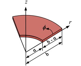
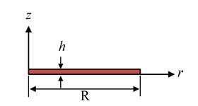
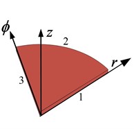
Consider a moderately thick annular sector plate with internal radius , outer radius , thickness and width in the radial direction as shown in Fig. 1. The angle represents the sector angle of the plate. The plate geometry and dimensions are defined in the cylindrical coordinate system .
Fig. 1Geometry of moderately thick annular sector plate
a)
b)
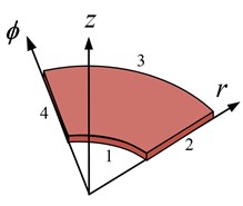
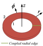
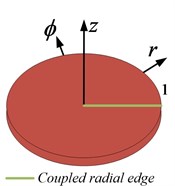
The elastic boundary conditions along the edges are specified using boundary spring technique. One translational and two rotational springs of arbitrary stiffness values are attached at each edge to simulate arbitrary boundary conditions. All the classical sets of boundary conditions can easily be achieved by varying the stiffness value of each spring from zero to an infinitely large number i.e. 1014. It can be seen in Fig. 2 that an annular plate can be obtained by annular sector plate when the sector angle becomes equal to 2, a circular sector plate can be obtained from annular sector plate if the inner radius becomes equal to 0. Similarly, a circular plate can be obtained when the inclusion angle of the annular sector plate becomes equal to 2 and the inner radius also becomes equal to 0. Therefore, the solution algorithm and procedure will be developed in such a way that it can easily be applied to annular, circular and circular sector plates just by varying geometric parameters mentioned earlier.
Fig. 2a) Annular sector plate, b) annular plate, c) circular sector plate, d) circular plate
a)
b)
c),
d),
2.2. Formulation
In the framework of first order shear deformation plate theory, the displacement field in an arbitrary point of a moderately thick annular sector pate is given by:
where and represents the rotation of transverse normal with respect to and directions, is the thickness coordinate, and are displacements of the mid plane in and directions, respectively, is the transverse displacement and is the time. Thus the corresponding strains at this point are defined in terms of middle surface strains, curvature and twist changes as:
where the middle surface strains, curvature and twist changes are written as:
Assuming the plain stress distribution in accordance with Hooks law, the stress resultants are obtained for Mindlin annular plate by integrating the stresses as shown below:
where , and are the bending moments per unit length of the plate, and are the transverse shear forces per unit length of the plate, , are the normal stresses, , and are the shear stresses, is the plate thickness, is the modulus of elasticity, is the shear modulus, is the Poisson ratio, is the flexural rigidity and is the shear correction factor to compensate for the error in assuming the constant shear stress throughout the plate thickness. The equation of motion of the Mindlin annular sector plate is given by:
The boundary conditions for an elastically restrained moderately thick annular sector plate are:
where , ( and are translational spring constants, , ( and are rotational spring constants attached in radial direction and , ( and are rotational spring constants attached in circumferential direction at and ( and respectively. All the classical homogeneous boundary conditions can be simply considered as special cases when the spring constants are either extremely large or substantially small. For instance, a clamped boundary (C) is achieved by simply setting the stiffness of the entire springs equal to infinity (which is represented by a very large number, 1014). Inversely, a free boundary (F) is gained by setting the stiffness of the entire springs equal to zero. The units for the translational and rotational springs are N/m and Nm/rad, respectively.
2.3. Trigonometric series representation for the displacement functions
Regardless of the plate shape and type of boundary conditions, the displacement and rotation functions are invariably expressed in the form of simple trigonometric series expansion as:
where , , denotes the expansion coefficients and:
A solution can be obtained either in strong form by letting the series satisfy the relevant equations exactly on a point-wise basis, or in weak form by solving the series coefficients approximately using, for instance, the Rayleigh-Ritz technique. The weak form of solution will be sought here since it will be more attractive in modeling complex structures. To employ this method for this analysis, it is necessary to state the potential and kinetic energy in terms of displacement fields. The total potential energy of the spring restrained plate which is composed of two parts, namely, the strain energy of the Mindlin annular sector plate is given by:
and the potential energy stored in the boundary springs, can be expressed as:
The kinetic energy expression for annular sector plate is expressed as:
As mentioned above, an annular plate can be mathematically viewed as a special case when the sector angle of an annular sector plate is set equal to 2. However, this transition of annular sector plate into annular plate is not possible with this simple mathematical operation because the continuity of the displacement and its derivatives at this simple mathematical operation alone cannot automatically ensure a complete transition of the sector into an annular plate that is, the continuities of the displacements and their derivatives at and . To overcome this problem, a set of coupling springs will be used to enforce the continuity conditions for the displacements at the edges and . The potential energy stored in these coupling springs will be given by:
where , and are the stiffnesses for translational coupling spring, rotational coupling springs in radial direction and rotational coupling springs in tangential direction respectively.
The Lagrangian for the annular sector plate can be generally expressed as:
Substituting Eqs. (9-11) in (12) and minimizing Lagrangian against all the unknown series expansion coefficients we can obtain a series of linear algebraic expressions in a matrix form as:
where is a vector which contains all the unknown series expansion coefficients that is:
And and are the stiffness and mass matrices, respectively. For conciseness, the detailed expressions for the stiffness and mass matrices are not shown here. The eigenvalues (or natural frequencies) and eigenvectors of moderately thick annular sector plates can now be easily and directly determined from solving a standard matrix eigenvalue problem Eq. (13). For a given natural frequency, the corresponding eigenvector actually contains the series expansion coefficients which can be used to construct the physical mode shape based on Eqs. (7).
3. Results and discussion
In order to verify the convergence, accuracy, reliability and applicability of the present method for moderately thick annular, circular plates and their sector counter parts, several numerical examples are presented here along with the reference results from literature and ABAQUS. First of all the convergence of the present method is studied. Using different truncation terms (2, 4, 6, 8, 10, 12, 14) several sets of results are obtained for fully clamped Mindlin annular sector plate having different sector angles and presented in Table 1 and 2 as shown.
Table 1First five non-dimensional frequency parameter for fully clamped Mindlin annular sector plate having a/b= 0.6, h/b= 0.1
Sector angle Ø | Non dimensional frequency parameter | |||||
Mode sequence | ||||||
1 | 2 | 3 | 4 | 5 | ||
2 | 145.584 | 240.451 | 251.723 | 331.721 | 391.843 | |
4 | 144.104 | 237.420 | 249.040 | 328.660 | 350.364 | |
6 | 144.032 | 237.301 | 248.941 | 328.487 | 349.816 | |
/6 | 8 | 144.020 | 237.280 | 248.924 | 328.452 | 349.739 |
10 | 144.017 | 237.274 | 248.920 | 328.442 | 349.720 | |
12 | 144.016 | 237.272 | 248.918 | 328.438 | 349.713 | |
14 | 144.015 | 237.271 | 248.917 | 328.436 | 349.711 | |
ABAQUS | 144.534 | 238.503 | 250.295 | 329.634 | 350.523 | |
Table 2First five non-dimensional frequency parameter for CCCC Mindlin annular sector plate having a/b= 0.6, h/b= 0.1
Sector angle Ø | Non Dimensional frequency parameter | |||||
Mode sequence | ||||||
1 | 2 | 3 | 4 | 5 | ||
2 | 104.250 | 116.563 | 163.387 | 223.325 | 232.424 | |
/2 | 4 | 102.977 | 112.649 | 130.467 | 173.504 | 220.564 |
6 | 102.911 | 112.460 | 129.978 | 155.396 | 187.319 | |
8 | 102.900 | 112.420 | 129.896 | 154.985 | 185.972 | |
10 | 102.897 | 112.408 | 129.871 | 154.895 | 185.781 | |
12 | 102.896 | 112.403 | 129.862 | 154.865 | 185.726 | |
14 | 102.895 | 112.401 | 129.857 | 154.852 | 185.705 | |
ABAQUS | 103.271 | 112.776 | 130.262 | 155.343 | 182.096 | |
A fast convergence can be observed in the tabulated results for different truncation numbers and also a good agreement can be observed between the present values and the ABAQUS results. Similarly figure 3 shows convergence pattern for the 1st, 3rd, 5th and 8th mode for a moderately thick circular sector plate having clamped circular edge and simply supported radial edges.
Fig. 3Convergence pattern for frequency parameters with no. of truncation terms
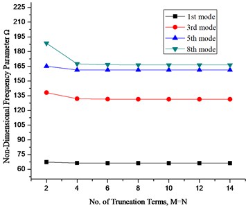
It can be seen that the results converge very quickly even with small number of truncation terms. Thus a suitable truncation number should be used to achieve the accuracy of the largest desired frequency. In view of above and excellent convergence behavior of the current solution, the truncation number for subsequent calculation in the present method is taken as 12.
After verifying the fast convergence of the preset method, results for Mindlin annular and circular plates and their sector counterparts are obtained and tabulated for various sector angles and different boundary conditions along with the reference results from literature. Table 3 shows fundamental frequency parameters for Mindlin annular sector plates having different sector angles and thickness to radius ratio. The plate has simply supported radial edges and different boundary conditions at the circular edges. The results have been compared with ABAQUS software as well as those available in literature.
Table 3Fundamental frequency parameter Ω=ωb2ρh/D1/2 for Mindlin annular sector plates having SS radial edges and various boundary conditions at the inner and outer circumferential edges (a/b= 0.5)
Sector angle Ø | Method | Boundary conditions | ||||
S-S | S-F | F-S | F-C | |||
195 | 0.1 | Present | 38.365 | 4.560 | 10.224 | 19.998 |
Ref [12] | 38.636 | 4.675 | 10.227 | 19.999 | ||
ABAQUS | 38.580 | 4.540 | 11.159 | 20.923 | ||
0.2 | Present | 32.508 | 4.005 | 9.130 | 17.503 | |
Ref [12] | 32.871 | 4.542 | 9.366 | 17.582 | ||
ABAQUS | 32.676 | 4.067 | 10.014 | 18.239 | ||
210 | 0.1 | Present | 38.222 | 4.507 | 9.685 | 19.620 |
Ref [12] | 38.455 | 4.584 | 9.664 | 19.610 | ||
ABAQUS | 38.223 | 4.230 | 9.479 | 19.516 | ||
0.2 | Present | 32.419 | 3.997 | 8.681 | 17.235 | |
Ref [12] | 32.734 | 4.458 | 8.877 | 17.294 | ||
ABAQUS | 32.469 | 3.923 | 8.590 | 17.201 | ||
270 | 0.1 | Present | 37.868 | 4.392 | 8.213 | 18.654 |
Ref [12] | 38.010 | 4.372 | 8.130 | 18.622 | ||
ABAQUS | 37.875 | 4.197 | 8.015 | 18.574 | ||
0.2 | Present | 32.200 | 3.999 | 7.450 | 16.548 | |
Ref [12] | 32.394 | 4.263 | 7.546 | 16.566 | ||
ABAQUS | 32.252 | 3.932 | 7.366 | 16.524 | ||
Next we verify the applicability of this unified method for annular plates. As mentioned previously an annular plate can be viewed as a special case of annular sector plate if the sector angle becomes equal to 2. Results for Mindlin annular plate for different combination of classical boundary conditions at the inner and outer edges for various cutout ratios are also calculated and presented in Table 4 along with those obtained from ABAQUS. A very close agreement can be observed in the calculated results. This close agreement verifies the applicability of the coupling spring technique for calculating frequency parameters for a complete annular plate without modifying the solution procedure.
Table 4Non dimensional frequency parameter Ω=ωb2ρh/D1/2 for Mindlin annular plates with various cutout ratio and boundary conditions (h/b= 0.2)
B.C | Method | Mode sequence | |||||
1 | 2 | 3 | 4 | 5 | |||
SC | 0.2 | Present | 21.161 | 22.228 | 22.228 | 27.545 | 27.550 |
ABAQUS | 21.200 | 22.271 | 22.272 | 27.596 | 27.596 | ||
0.4 | Present | 32.154 | 32.829 | 32.829 | 35.411 | 35.414 | |
ABAQUS | 32.243 | 32.920 | 32.920 | 35.511 | 35.511 | ||
0.6 | Present | 56.120 | 56.458 | 56.458 | 57.642 | 57.643 | |
ABAQUS | 56.357 | 56.697 | 56.697 | 57.885 | 57.887 | ||
SF | 0.2 | Present | 2.082 | 2.082 | 3.225 | 4.980 | 4.998 |
ABAQUS | 2.084 | 2.084 | 3.224 | 4.975 | 4.975 | ||
0.4 | Present | 3.280 | 3.280 | 3.581 | 5.464 | 5.471 | |
ABAQUS | 3.282 | 3.282 | 3.578 | 5.465 | 5.465 | ||
0.6 | Present | 4.703 | 5.089 | 5.089 | 7.402 | 7.407 | |
ABAQUS | 4.699 | 5.090 | 5.090 | 7.411 | 7.411 | ||
FC | 0.2 | Present | 9.476 | 16.774 | 16.774 | 26.240 | 26.247 |
ABAQUS | 9.481 | 16.797 | 16.797 | 26.288 | 26.289 | ||
0.4 | Present | 12.156 | 15.995 | 15.995 | 24.240 | 24.246 | |
ABAQUS | 12.163 | 16.014 | 16.014 | 24.248 | 24.284 | ||
0.6 | Present | 21.219 | 22.812 | 22.812 | 27.275 | 27.278 | |
ABAQUS | 21.244 | 22.844 | 22.844 | 27.324 | 27.325 | ||
CF | 0.2 | Present | 4.191 | 4.191 | 4.809 | 5.750 | 5.756 |
ABAQUS | 4.193 | 4.193 | 4.810 | 5.746 | 5.748 | ||
0.4 | Present | 8.017 | 8.017 | 8.175 | 8.865 | 8.868 | |
ABAQUS | 8.022 | 8.022 | 8.179 | 8.870 | 8.870 | ||
0.6 | Present | 17.148 | 17.198 | 17.198 | 17.802 | 17.803 | |
ABAQUS | 17.168 | 17.220 | 17.220 | 17.826 | 17.826 | ||
CC | 0.2 | Present | 24.346 | 25.313 | 25.313 | 29.515 | 29.519 |
ABAQUS | 24.413 | 25.380 | 25.380 | 29.583 | 29.584 | ||
0.4 | Present | 37.641 | 38.196 | 38.196 | 40.238 | 40.240 | |
ABAQUS | 37.784 | 38.339 | 38.339 | 40.382 | 40.383 | ||
0.6 | Present | 64.159 | 64.462 | 64.462 | 65.485 | 65.486 | |
ABAQUS | 64.496 | 64.799 | 64.800 | 65.821 | 65.823 | ||
As mentioned earlier when the inner radius of an annular sector plate is approximated to a very small number say 0.00001, then the annular sector plate converges to circular sector plate. The same method has been applied to circular sector plates and results for circular sector plates having different sector angles and boundary conditions at the radial and circumferential edges It should be noted that the symbol S stands for simply supported, C stands for clamped and F stand for free boundary conditions. The edges are taken in the counter clock wise direction, so SCS boundary conditions means simply supported radial edges and clamped circumferential edge. First three non-dimensional frequency parameters are calculated and presented in the Table 5 along with the reference results. It can be observed that the frequency parameters are in close agreement with the reference data.
Next we calculate the frequency parameter for various boundary conditions for a complete Mindlin circular plate having different thickness to radius ratio. In order to achieve this two simple modification needs to be done in the solution algorithm. First is equating the inner radius equal to a very small number say 0.00001 and second is equating the sector angle equal to 2 Table 6 presents first five non dimensional frequency parameter for a complete circular plate subjected to different boundary conditions at the circumferential edge and having different thickness to radius ratio. It should be noted that for the ‘F’; free boundary condition; the zero frequency parameters for the first six rigid body modes have not been taken into account in the Table 6. It can be observed that the frequency parameter decreases with increasing thickness to radius ratio in all the three types of boundary conditions listed. A good agreement between the presented results and those obtained through ABAQUS can also be observed which proves the applicability of the present method for calculating the frequency parameters for Mindlin circular plates also.
Table 5First three non-dimensional frequency parameters Ω=ωb2ρh/D1/2 for circular sector plates having different combination of classical boundary conditions and sector angle (h/b= 0.2, a/b= 0.00001)
Sector angle Ø | BC | Mode sequence | Present | Ref. [13] | ABAQUS |
30 | SCS | 1 | 66.256 | 67.933 | 66.490 |
2 | 98.936 | 102.560 | 99.373 | ||
3 | 131.364 | 132.860 | 132.146 | ||
90 | SSS | 1 | 21.006 | 21.977 | 21.030 |
2 | 41.254 | 42.699 | 41.339 | ||
3 | 48.863 | 50.307 | 48.981 | ||
120 | CCC | 1 | 27.311 | 27.314 | 27.372 |
2 | 40.977 | 40.983 | 41.105 | ||
3 | 52.324 | 52.338 | 52.515 |
Table 6First five non-dimensional frequency parameter Ω=ωb2ρh/D1/2 for a Mindlin circular plate having different boundary conditions and thickness to radius ratio (a/b= 0.00001)
B.C | Method | Mode Sequence | |||||
1 | 2 | 3 | 4 | 5 | |||
C | 0.1 | Present | 9.941 | 20.178 | 20.178 | 32.210 | 32.223 |
ABAQUS | 9.939 | 20.176 | 20.176 | 32.220 | 32.222 | ||
0.2 | Present | 9.240 | 17.758 | 17.758 | 26.994 | 27.000 | |
ABAQUS | 9.246 | 17.782 | 17.782 | 27.044 | 27.045 | ||
0.25 | Present | 8.807 | 16.446 | 16.446 | 24.478 | 24.482 | |
ABAQUS | 8.816 | 16.479 | 16.479 | 24.540 | 24.540 | ||
S | 0.1 | Present | 4.895 | 13.512 | 13.512 | 24.324 | 24.336 |
ABAQUS | 4.892 | 13.508 | 13.508 | 24.315 | 24.317 | ||
0.2 | Present | 4.777 | 12.620 | 12.620 | 21.690 | 21.696 | |
ABAQUS | 4.776 | 12.625 | 12.625 | 21.710 | 21.710 | ||
0.25 | Present | 4.696 | 12.080 | 12.080 | 20.272 | 20.276 | |
ABAQUS | 4.696 | 12.089 | 12.089 | 20.300 | 20.300 | ||
F | 0.1 | Present | 5.283 | 5.299 | 8.869 | 12.153 | 12.248 |
ABAQUS | 5.275 | 5.275 | 8.865 | 12.062 | 12.062 | ||
0.2 | Present | 5.117 | 5.125 | 8.505 | 11.366 | 11.428 | |
ABAQUS | 5.113 | 5.113 | 8.504 | 11.316 | 11.316 | ||
0.25 | Present | 5.011 | 5.018 | 8.268 | 10.910 | 10.960 | |
ABAQUS | 5.009 | 5.009 | 8.268 | 10.871 | 10.871 | ||
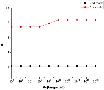
All the results tabulated so far have been calculated for various combinations of classical boundary conditions which are treated as a special case of elastic boundary conditions in which the stiffness values for the restraining springs are set either equal to a very high value i.e. 1014 or a very low number zero. It is therefore necessary to study the effect of these restraining spring stiffnesses on the frequency characteristics for these plates. Figs. 4-6 shows the effect of boundary restraining springs on the frequency parameter ‘’ for a fully clamped annular plate having 0.6 and 0.2.
Fig. 4 shows effect of translational spring stiffness on the second and sixth mode frequency parameter of annular plate in which the stiffness of the translational spring stiffness varies from 0 to 1e14 while the stiffnesses of the rotational spring in radial and tangential direction ( ) are kept constant i.e. 1e14.
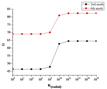
Similarly, Figs. 5 and 6 have been obtained by assigning the corresponding boundary spring stiffness, a value ranging from 0 to 1014 and keeping the stiffnesses of other sets of spring equal to 1014.
Fig. 4Effect of translational spring stiffness k on frequency parameter Ω
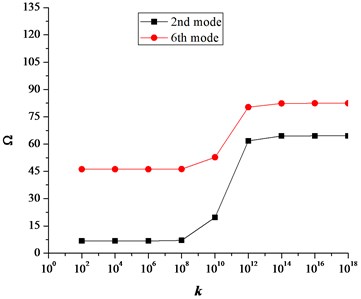
Fig. 5Effect of rotational spring stiffness K attached in tangential direction on Ω
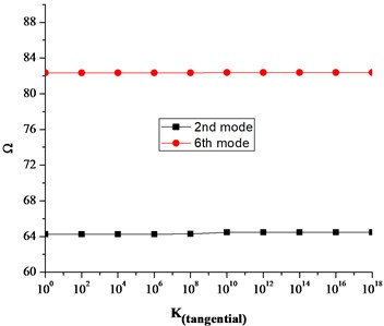
Fig. 6Effect of rotational spring stiffness K attached in radial direction on Ω
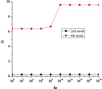
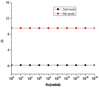
Similarly, Fig. 7(a)-(c) shows the effect of coupling springs on the frequency parameter .
It can be seen that the translational and rotational boundary springs sufficiently affect the frequency parameters. More precisely the translational boundary restraining spring tend to be more influential when its stiffness varies from 108 to 1013. Similarly, the influential range for the rotational boundary spring in the radial direction is 106 to 1012. However, the influence of rotational boundary spring in the tangential direction is very small as seen in Fig. 5. Also it can be seen in Fig. 7(a)-(c) that influential range for the coupling springs is much smaller as compared to the boundary restraining springs. This influential range is the elastic range and frequency parameters can easily be calculated for elastic boundary conditions by assigning the proper stiffness values to the boundary restraining springs without modifying the solution procedure or algorithms.
We know that in practical engineering, designing or development of any mechanical system or a product, structure vibration analysis and testing is an important part to assess the real behavior of the structure when subjected to static or dynamic loads. In other words, to better understand any structural vibration problem, the resonant frequencies of a structure need to be identified and quantified in order to avoid well known resonance phenomena which can result in catastrophe. Today, modal analysis has become a widespread means of finding the modes of vibration of a machine or a structure.
Fig. 7Effect of coupling springs on the frequency parameter Ω
a) Effect of translational coupling spring on frequency parameter
b) Effect of rotational coupling spring in radial direction on frequency parameter
c) Effect of rotational coupling spring in tangential direction on frequency parameter
Various analytical methods have been developed over the years to accurately estimate the resonant frequencies or modes of vibrations of any structure when subjected to different boundary conditions. Once these frequencies are calculated they are used to estimate the modes of vibrations of a structure which are determined by the material properties and boundary conditions. Each mode of vibration is defined by a natural (modal or resonant) frequency, modal damping, and a mode shape. If there is a slight change in material properties or boundary conditions of a structure, its modes of vibration will also change. Therefore, it is important to estimate these frequencies for any change in material properties as well as boundary conditions because in practical engineering applications, the material properties of a structure and boundary conditions may vary. Furthermore, most of the existing techniques available so far to estimate these natural or resonant frequencies are limited to classical boundary conditions (clamped, free, simply supported etc.), however in practical engineering applications the structures are not always subjected to classical boundary conditions rather they may be subjected to elastic boundary conditions.
In the present manuscript, the unified method presented not only helps to accurately estimate these natural frequencies of circular and annular plates and their sector counter parts when they are subjected to classical boundary conditions but also when they are subjected to general elastic boundary conditions. The presented results give an insight of the modes of vibration of these plates having different material properties and subjected to elastic boundary conditions. Moreover, another important contribution of this technique is that this method does not require any changes in procedure or solution algorithms to accommodate different geometries, material properties or boundary conditions. The same solution algorithm or procedure can be used to estimate natural frequencies for different materials and boundary conditions. Different boundary conditions (classical, elastic, uniform & non-uniform) can easily be achieved by simply changing the stiffnesses of the translational and rotational springs attached at the boundaries or edges of these plates”.
4. Conclusion
In this paper a unified method is presented for vibration analysis of Mindlin annular, circular and their sector counter parts with arbitrary boundary conditions at their edges. Coupling springs technique has been utilized to avoid inconvenient formulation or procedural modification to accommodate different boundary conditions and geometrical shapes of the plates. Irrespective of the shape of the plate and the type of boundary conditions, each of the displacement function is expressed as a new form of trigonometric expansion with high convergence rate. Rayleigh-Ritz method has been used to determine the expansion coefficients. The current method therefore can be universally applied to a wide range of vibration problems involving different shapes, boundary conditions, varying materials and geometric properties without modifying the solution algorithms and procedure. The unification, fast convergence, accuracy and reliability have been fully demonstrated through several numerical examples involving different shapes and boundary conditions. Furthermore, the effect of boundary restraining springs and coupling springs on the frequency parameter have also been studied.
References
-
Deresiewicz H., Mindlin R. D. Axially symmetric flexural vibrations of a circular disk. American Society of Mechanical Engineers Journal of Applied Mechanics, Vol. 22, 1955, p. 86-88.
-
Soni S. R., Amba Rao C. L. On radially symmetric vibrations of orthotropic non uniform disks including shear deformation. Journal of Sound and Vibration, Vol. 42, 1975, p. 57-63.
-
Gupta U. S., Lal R. Axisymmetric vibrations of polar orthotropic Mindlin annular plates of variable thickness. Journal of Sound and Vibration, Vol. 98, 1985, p. 565-573.
-
Cheung Y. K., Kwok W. L. Dynamic analysis of circular and sector thick layered plates. Journal of Sound and Vibration, Vol. 42, 1975, p. 147-158.
-
Cheung M. S., Chan M. Y. T. Static and dynamic analysis of thin and thick sectorial plates by the finite strip method. Computers and Structures, Vol. 14, 1981, p. 79-88.
-
Xiang Y., Liew K. M., Kitipornchai S. On transverse vibration of thick annular sector plates. Transactions of the American Society of Civil Engineers, Journal of Engineering Mechanics, Vol. 119, Issue 8, 1993, p. 1579-1599.
-
Liew K. M., Kitipornchai S., Xiang Y. Vibration of annular sector Mindlin plates with internal radial line and circumferential arc supports. Journal of Sound and Vibration, Vol. 183, Issues 3-8, 1995, p. 401-419.
-
Xiang Y., Liew K. M., Kitipornchai S. Vibrations of circular and annular Mindlin plates with internal ring stiffeners. Journal of Acoustical Society of America, Vol. 100, Issue 6, 1996, p. 3696-3705.
-
Kitipornchai S., Xiang Y., Liew K. M. Vibration analysis of corner supported Mindlin plates of arbitrary shape using the Lagrange multiplier method. Journal of Sound and Vibration, Vol. 173, Issue 4, 1994, p. 457-470.
-
Bani Singh, Saleh Hassan M. Transverse vibration of a circular plate with arbitrary thickness variation. International Journal of Mechanical Science, Vol. 40, Issue 11, 1998, p. 1089-1104.
-
Xiang Y., Zhang L. Free vibration analysis of stepped circular Mindlin plates. Journal of Sound and Vibration, Vol. 280, 2005, p. 633-655.
-
Mcgee O. G., Huang C. S., Leissa A. W. Comprehensive exact solutions for free vibrations of thick annular sectorial plates with simply supported radial edges. International Journal of Mechanical Sciences, Vol. 37, Issue 5, 1995, p. 537-566.
-
Liu F. L., Liew K. M. Free vibration analysis of Mindlin sector plates: numerical solutions by differential quadrature methods. Computer Methods in Applied Mechanics and Engineering, Vol. 177, 1999, p. 77-92.
-
Liew K. M., Liu F. L. Differential quadrature method for free vibrations of shear deformable annular sector plates. Journal of Sound and Vibration, Vol. 230, Issue 2, 2000, p. 335-356.
-
Wu T. Y., Liu G. R. Free vibration analysis of circular plates with variable thickness by the generalized differential quadrature rule. International Journal of Solid and Structures, Vol. 38, 2001, p. 7967-7980.
-
Huang C. S., Ho K. H. An analytical solution for vibrations of polarly orthotropic Mindlin sectorial plate with simply supported radial edges. Journal of Sound and Vibration, Vol. 273, 2004, p. 277-294.
-
Jae Hoon Kang Three-dimensional vibration analysis of thick circular and annular plates with non-linear thickness variation. Computers and Structures, Vol. 81, 2003, p. 1663-1675.
-
So J., Leissa A. W. Three dimensional vibrations of thick circular and annular plates. Journal of Sound and Vibration, Vol. 209, 1998, p. 15-41.
-
Zhou D., Au F. T. K., Cheung Y. K., Lo S. H. Three-dimensional vibration analyses of circular and annular plates via the Chebyshev-Ritz method. International Journal of Solid and Structures, Vol. 40, 2003, p. 3089-3105.
-
Zhou D., Lo S. H., Cheung Y. K. 3-D vibration analysis of annular sector plates using the Chebyshev-Ritz method. Journal of Sound and Vibration, Vol. 320, 2009, p. 421-437.
-
Hashemi S. H., Tahir H. R. D., Omidi M. 3-D free vibration analysis of annular plates on Pasternak elastic foundation via p-Ritz method. Journal of Sound and Vibration, Vol. 311, 2008, p. 1114-1140.
-
Civalek Omer, Gurses Murat Free vibration of annular Mindlin plates with free inner edge via discrete singular convolution method. The Arabian Journal for Science and Engineering, Vol. 34, Issue 1, 2009, p. 81-90.
-
Civalek Omer, Ersoy Haken Free vibration and bending analysis of circular Mindlin plates using singular convolution method. Communications in Numerical Methods in Engineering, Vol. 25, 2009, p. 907-922.
-
Jomehzadeh E., Saidi A. R. Analytical solution for the free vibration of transversely isotropic sector plates using a boundary layer function. Thin Walled Structures, Vol. 47, 2009, p. 82-88.
-
Jomehzadeh E., Saidi A. R. Accurate natural frequencies of transversely isotropic moderately thick annular sector plates. Journal of Mechanical Engineering Science, Vol. 223, Issue 2, 2009, p. 307-317.
-
Bashmal S., Bhat R., Rakheja S. Frequency equations for the in-plane vibration of circular annular disks. Advances in Acoustic and Vibrations, Vol. 2010, 2010.
-
Bashmal S., Bhat R., Rakheja S. In-plane free vibration analysis of an annular disk with point elastic support. Journal of Shock and Vibration, Vol. 18, 2011, p. 627-640.
-
Karamooz Ravari M. R., Forouzan M. R. Frequency equations for the in-plane vibration of orthotropic circular annular plates. Archives of Applied Mechanics, Vol. 81, 2010, p. 1307-1322.
-
Sari M. S., Butcher E. A. Free vibration analysis of rectangular and annular Mindlin plates with undamaged and damaged boundaries by the spectral collocation method. Journal of Vibration and Control, 2011, p. 1-15.
-
Bisadi H., Es’haghi M., Rokni H., Ilkhani M. Benchmark solution for transverse vibration of annular Reddy plates. International Journal of Mechanical Sciences, Vol. 56, 2012, p. 35-49.
-
Mehdi Es’Haghi Accurate approach implementation in vibration analysis of thick sector plates. International Journal of Mechanical Sciences B, Vol. 79, 2014, p. 1-14.
-
Shi Dongyan, Shi Xianjie, Li Wen, Wang Qingshan Dynamic analysis of annular sector plates with general boundary supports. Structural Acoustics and Vibrations ICA, Montreal, Canada, Vol. 19, 2013.
-
Shi Xianjie, Shi Dongyan, Qin Zhengrong, Wang Qingshan In-plane vibration analysis of annular plates with arbitrary boundary conditions. The Scientific World Journal, Vol. 2014, 2014.
-
Shi Xianjie, Shi Dongyan, Li Wen L., Wang Qingshan A unified method for free vibration of circular, annular and sector plates with arbitrary boundary conditions. Journal of Vibration and Control, 2014.
About this article

The authors gratefully acknowledge the financial support from the National Natural Science Foundation of China (No. U1430236) and Natural Science Foundation of Heilongjiang Province of China (No. E2016024)
