Abstract
In this paper, an improved Fourier series method is presented for vibration analysis of moderately thick annular and circular sector plates subjected to general elastic boundary conditions along its edges. In literature, annular and circular sector plates subjected to classical boundary conditions have been studied in detail however in practical engineering applications the boundary conditions are not always classical in nature. Therefore, study of vibration response of these plates subjected to general elastic boundary conditions is far needed. In the method presented, artificial boundary spring technique has been employed to simulate the general elastic boundary conditions and first order shear deformation theory has been employed to formulate the theoretical model. Irrespective of the boundary conditions, each of the displacement function is expressed as a new form of trigonometric expansion with accelerated convergence. Rayleigh-Ritz method has been employed to determine the expansion coefficients. Unlike most of the studies on vibration analysis of moderately thick annular sector plates, the present method can be universally applied to a wide range of vibration problems involving different boundary conditions, varying material and geometric properties without modifying the solution algorithms and procedure. The effectiveness, reliability and accuracy of the present method is fully demonstrated and verified by several numerical examples. Bench mark solutions for moderately thick annular sector and circular plates under general elastic boundary conditions are also presented for future computational methods.
1. Introduction
Annular, circular and their sector parts are key structural components that are used in various engineering fields like civil, marine, aerospace and mechanical engineering. Due to different geometrical shapes of these structures, they have been analyzed separately using different solution techniques. Most of the initial research on these plates was done using Classical plate theory (CPT) in which the shear deformation and rotary inertia was neglected which in turn limited its application on moderately thick and thick plates. Later a lot of theories were proposed incorporating the shear deformation and rotary inertia which resulted in an increase in accuracy of the results for moderately thick and thick annular and circular plates. These theories’ have been well explained in Leissa’s book on vibration of plates.
Different methods have been employed by various researchers to study the vibration characteristics of annular and circular plates subjected to different boundary conditions. However, a few prominent studies related to these plates are highlighted here in this manuscript. Employing the Mindlin plate theory on thick sector plates, Guruswamy et al. [1] studied the dynamic response of these plates by proposing a sector finite element. Fully clamped boundary conditions were employed on all edges. Taking the effect of shear deformation in thickness direction, another study was performed by Soni et al. [2] on axisymmetric non uniform circular disks. In their research they employed Chebyshev collocation technique to study the vibration characteristics of these plates. In another study Rayleigh-Ritz method was employed by Liew et al. on circular plates with multiple internal ring supports. Later in another study they studied the characteristics of these plates subjected to in-plane pressure [3-4].
Using three dimensional finite strip model, thick and thin sector plates subjected to various combinations of classical boundary condition were analyzed by Cheung et al. [5]. The integral equation technique and finite strip method was employed by Sirinivasan et al. and Misuzawa et al. respectively to study the vibration characteristics of Mindlin annular sector plates [6-7]. Employing the Mindlin plate theory and differential quadrature method, Liu et al. studied the effect of sector angle and thickness to radius ratio on the vibration characteristics of moderately thick sector plates [8]. Later they extended the same differential quadrature method to annular sector plates having shear deformation subjected to different combinations of classical boundary conditions [9]. In another study, the same differential quadrature method was employed on solid circular plates with variable thickness in radial direction and subjected to elastic boundary conditions by Wu et al. [10]. Similarly, Xiang et al. employed domain decomposition technique and studied the vibration response of circular plates with stepped thickness variation [11].
Using Rayleigh-Ritz method So et al. [12] studied the vibration characteristics of annular and circular plates by employing three dimensional elasticity theory. A similar three dimensional study was performed by Hashemi et al. on annular sector plates resting on elastic foundations. He employed polynomial-Ritz approach and studied the vibration characteristics for different sets of classical boundary conditions [13]. In another study similar polynomial-Ritz model was presented by Liew et al. to investigate the effect of boundary conditions and thickness on the vibration characteristics of annular plates [14]. In another prominent three dimensional study Chebyshev-Ritz technique was employed on circular and annular plates by Zhou et al. to study the vibration characteristics of these plates [15]. In plane vibrations of circular plates subjected to different boundary conditions were investigated by various researchers using different solution techniques [16-17]
From the studies mentioned above it can be seen that most of the previous studies on annular and circular plates were limited to classical boundary conditions which includes free, simply supported, clamped or combination of these. However, in practical engineering applications the boundary conditions are not always classical in nature. Therefore, the development of an analytical method universally dealing with arbitrary boundary conditions was much needed. An improved Fourier series method was developed for vibration analysis of beams and plates by Li [18-22]. Later Xianjie Shi et al. extended this method to thin annular plates to study its vibration characteristics [23-26]. The main objective of this study is to realize and extend the same generalized Fourier series method to study the vibration analysis of Mindlin annular sector and circular sector plates under various boundary conditions including the general elastic restraints.
2. Theoretical formulation
2.1. Model description
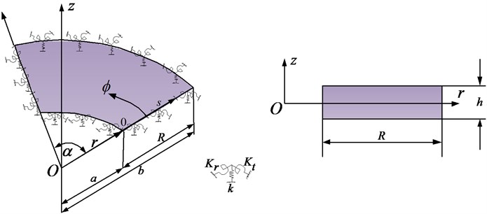
Consider an annular sector plate of constant thickness , inner radius , outer radius and width in radial direction as shown in Fig. 1. The plate geometry and dimensions are defined in the cylindrical coordinate system . A local coordinate system is also shown in Fig. 1. The radial and thickness coordinates and are measured normally from the inner edge and mid plane of the annular sector plate respectively whereas is the circumferential angle. Four sets of distributed springs (one translational and two rotational) of arbitrary stiffness values are attached at each edge to simulate arbitrary boundary conditions. All the classical sets of boundary conditions can easily be achieved by varying the stiffness value of each spring from zero to an infinitely large number i.e. 1014.
The domain of the annular sector plate can be defined as:
The relationship between local and global coordinate system can be expressed as:
The material of the plate is assumed to be isotropic with material density , young’s modulus and Poisson ratio . It should be noted that a circular sector plate can be defined as a special case of an annular sector plate if the inner radius ‘’ is set either equal to 0 or to a very small number say 0.00001.
The displacement field of Mindlin annular sector plate in cylindrical coordinates is given by:
where is the thickness coordinate, and are displacements of the mid plane in and directions, respectively, is the transverse displacement. and are the rotation functions of the middle surface and is the time. Assuming the plain stress distribution in accordance with Hooks law, the stress resultants are obtained for Mindlin annular plate by integrating the stresses as shown below:
where , and are the bending moments per unit length of the plate, and are the transverse shear forces per unit length of the plate, , are the normal stresses, and , and are the shear stresses, is the plate thickness, is the modulus of elasticity, is the shear modulus, is the Poisson ratio, is the flexural rigidity and is the shear correction factor to compensate for the error in assuming the constant shear stress throughout the plate thickness.
The equation of motion of Mindlin plates in is given by:
Fig. 1Mindlin sector plate geometry
2.2. Solution scheme
2.2.1. Selection of admissible displacement function
Assume that the displacement field of Mindlin annular sector plate in local coordinate system is defined by the following series:
where:
and and denotes the Fourier series expansion coefficients. The sine terms in the equations Eq. (6) are introduced to overcome the potential discontinuities (convergence problem) of the displacement function, along the edges of the plate, when it is periodically extended and sought in the form of trigonometric series expansion. The addition of these auxiliary functions in the admissible functions plays an important role in the convergence and accuracy of the present method or in other words the elimination of potential discontinuities at the ends or elimination of Gibbs effect.
In order to illustrate this, take a beam problem for example. The governing equations for free vibration of a general supported Euler beam is obtained as:
where , and are, respectively, the flexural rigidity, the mass density and the cross sectional area of the beam, and is frequency in radian. From Eq. (7) it can be observed that the displacement solution on a beam of length is required to have up to the fourth derivatives, that is, . In general, the displacement function defined over a domain [0, ] can be expanded into a Fourier series inside the domain excluding the boundary points:
where are the expansion coefficients. From the Eq. (8), we can see that the displacement function can be viewed as a part of an even function defined over , as shown in Fig. 2.
Fig. 2An illustration of the possible discontinuities of the displacement at the end points
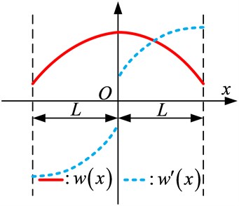
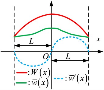
Fig. 3An illustration of removal of possible discontinuities (convergence problem) at ends
Thus, the Fourier cosine series is able to correctly converge to at any point over [0, ]. However, its first-derivative is an odd function over leading to a jump at end locations. The corresponding Fourier expansion of continue on [0, ] and can be differentiated term-by-term only if . Thus, its Fourier series expansion (sine series) will accordingly have a convergence problem due to the discontinuity at end points (Gibbs phenomena) when is required to have up to the first-derivative continuity.
To overcome this problem, this Improved Fourier Series technique was proposed by Li [18, 19]. In this technique a new function is considered in the displacement function:
where the auxiliary function in equation above represents an arbitrary continuous function that, regardless of boundary conditions, is always chosen to satisfy the following equations:
The actual values of the first and third derivatives (a sine series) at the boundaries need to be determined from the given boundary conditions. Essentially, represents a residual beam function which is continuous over [0, ] and has zero slopes at the both ends, as shown in Fig. 3. Apparently, the cosine series representation of is able to converge correctly to the function itself and its first derivative at every point on the beam.
Thus, based on the above analysis, can be understood as a continuous function that satisfies Eq. (9), and its form is not a concern but must be a closed-form and sufficiently smooth over a domain [0, ] of the beam in order to meet the requirements provided by the continuity conditions and boundary constraints. Furthermore, it is noticeable that the auxiliary function can improve the convergent properties of Fourier series.
2.2.2. Determining the expansion coefficients
Once the proper admissible function for the displacement field is selected Eq. (6), the next step is to find the expansion coefficients in the assumed displacement field. In order to do so Rayleigh-Ritz method is employed which is an energy-based method. To employ this method, it is necessary to state the potential and kinetic energies first in terms of displacement fields. The expression for the potential energy of the sector plate in local coordinates is derived from the constitutive laws and strain-displacement relations. According to the Mindlin plate theory. The strain energy of the annular sector plates can be expressed as:
the kinetic energy expression for annular sector plate is expressed as:
The potential energy stored in the boundary springs is given by:
where , ( and ) are linear spring constants, , ( and ) are rotational spring constants in radial direction, , ( and ) are rotational spring constants in tangential direction at edges 0 and and 0 and respectively. All the classical homogeneous boundary conditions can be simply considered as special cases when the spring constants are either extremely large or substantially small. The units for the translational and rotational springs are N/m and Nm/rad, respectively.
After the potential and kinetic energies are expressed, then all the assumed displacement functions are inserted in the potential and kinetic energy equations and these equations are then further minimized with respect to the expansion coefficients in the displacement field. Mathematically, the Lagrangian for the annular sector plate can be generally expressed as:
where is strain energy of the plate, is strain energy stored in the boundary springs and is the kinetic energy of the plate. Substituting Eq. (6) in Eqs. (11)-(13) and then minimizing Lagrangian Eq. (14) against all the unknown series expansion coefficients that is:
we can obtain a series of linear algebraic expressions in a matrix form as:
where is a vector which contains all the unknown series expansion coefficients and and are the stiffness and mass matrices, respectively. , and can be expressed as:
where the subscripts , and represents , and and the superscripts and represents plate and boundary springs respectively. For conciseness, the detailed expressions for the stiffness and mass matrices are not shown here.
2.2.3. Determining the eigen values and eigen vectors
Once Eq. (16) is established, the eigenvalues (or natural frequencies) and eigenvectors of Mindlin annular sector plates can now be easily and directly determined from solving a standard matrix eigenvalue problem i.e. Eq. (16) using MATLAB. For a given natural frequency, the corresponding eigenvector actually contains the series expansion coefficients which can be used to construct the physical mode shape based on Eq. (6). Although this investigation is focused on the free vibration of Mindlin annular sector plate, the response of the annular sector plate to an applied load can be easily considered by simply including the work done by this load in the Lagrangian, eventually leading to a force term on the right side of Eq. (16).
3. Results and discussion
To check the accuracy and usefulness of the proposed technique, several numerical examples are presented in this section. It is important to mention here that the accuracy of the proposed method is greatly controlled by the number of truncation terms i.e. , the more number of truncation terms we use we get more accurate results however the computational cost and time will increase with increasing number of truncation terms. Theoretically, there are infinite terms in the assumed displacement functions. However, the series is numerically truncated and finite terms are counted in actual calculations which will be further explained in the text to follow. Moreover, in identifying the boundary conditions in this section, letters C, S, and F have been used to indicate the clamped, simply supported and free boundary condition along an edge, respectively. Therefore, the boundary conditions for a plate are fully specified by using four alphabets with the first one indicating the B.C. along the first edge, . The remaining (the second to the fourth) edges are ordered in the counterclockwise direction.
First of all, in order to check the accuracy and usefulness we first consider a fully clamped Mindlin annular sector plate. Fully clamped (CCCC) boundary conditions can easily be achieved by setting the stiffnesses of the restraining springs to an infinitely large number (1014) in the numerical calculations. The first six non-dimensional frequency parameter, are tabulated in Table 1 along with the reference results from [9] and [27].
Table 1First six non dimensional frequency parameter Ω=ωb2ρh/D1/2 for fully clamped (CCCC) Mindlin Annular sector plates (ϕ=2π/3, a/b= 0.25, h/b= 0.2)
Mode sequence | ||||||
1 | 2 | 3 | 4 | 5 | 6 | |
2 | 31.481 | 42.907 | 62.894 | 66.199 | 73.800 | 94.776 |
4 | 31.084 | 41.872 | 56.108 | 62.435 | 72.906 | 75.775 |
6 | 31.059 | 41.823 | 55.972 | 62.411 | 71.269 | 72.862 |
8 | 31.054 | 41.813 | 55.951 | 62.406 | 71.148 | 72.852 |
10 | 31.053 | 41.810 | 55.946 | 62.405 | 71.125 | 72.849 |
12 | 31.053 | 41.809 | 55.943 | 62.404 | 71.118 | 72.847 |
14 | 31.053 | 41.809 | 55.942 | 62.404 | 71.116 | 72.847 |
Ref. [9] | 31.056 | 41.814 | 55.951 | 62.420 | 71.127 | 72.862 |
Ref. [27] | 31.057 | 41.814 | 55.951 | 62.420 | 71.127 | 72.862 |
Similarly, in Table 2, first six non-dimensional frequency parameter for Mindlin annular sector plate having simply supported radial edges and clamped circumferential edges (CSCS) boundary conditions has been given along with the reference results from [9, 27]. A good agreement in the present values and reference values can be observed.
Table 2First six non dimensional frequency parameter Ω=ωb2ρh/D1/2 for Mindlin Annular sector plates (ϕ=π/3, a/b= 0.5, h/b= 0.1) having simply supported radial edges and clamped circumferential edges (CSCS)
Mode sequence | ||||||
1 | 2 | 3 | 4 | 5 | 6 | |
2 | 77.625 | 104.054 | 161.254 | 170.932 | 194.112 | 243.145 |
4 | 76.567 | 102.955 | 149.795 | 166.952 | 190.467 | 215.603 |
6 | 76.476 | 102.765 | 149.410 | 166.772 | 190.093 | 206.703 |
8 | 76.449 | 102.696 | 149.323 | 166.726 | 189.961 | 206.315 |
10 | 76.439 | 102.667 | 149.290 | 166.710 | 189.908 | 206.228 |
12 | 76.435 | 102.654 | 149.275 | 166.703 | 189.883 | 206.196 |
14 | 76.432 | 102.647 | 149.267 | 166.699 | 189.871 | 206.182 |
Ref. [9] | 76.902 | 103.682 | 150.413 | 167.327 | 191.593 | 207.276 |
Ref. [27] | 76.902 | 103.682 | 150.413 | 167.327 | 191.593 | 207.276 |
Next we consider annular sector plate simply supported at radial edges and having different combination of boundary conditions (free-clamped, free-simply supported, simply supported-simply supported, simply supported-free and clamped-free) at the circumferential edges. The simply supported condition is simply produced by setting the stiffnesses of the translational and rotational springs to and 0, respectively, and the free edge condition by setting both stiffnesses to zero. The fundamental frequency parameters with different boundary conditions are shown in Table 3. The current results agree well with those taken from references [28, 29].
Next to illustrate the convergence and numerical stability of the current solution procedure, several sets of results for fully clamped Mindlin annular sector plates having different sector angles and using different truncation numbers (2, 4, 6, 8, 10, 12, 14) are presented in Tables 4-7. Furthermore, the fast convergence pattern can also be observed in Fig. 4.
Table 3Fundamental frequency parameter Ω=ωb2ρh/D1/2 for Mindlin Annular sector plates having simply supported radial edges and different boundary conditions at circumferential edges (a/b= 0.5)
Sector angle () | Thickness to radius ratio () | Method | Boundary conditions at circumferential edges | ||||
F-C | F-S | S-S | S-F | C-F | |||
195 | 0.1 | Present | 19.998 | 10.224 | 38.365 | 4.560 | 12.696 |
Ref. [28] | 19.999 | 10.227 | 38.636 | 4.675 | 12.680 | ||
Ref. [29] | 20.097 | 10.239 | 38.764 | – | – | ||
0.2 | Present | 17.503 | 9.130 | 32.508 | 4.005 | 11.413 | |
Ref. [28] | 17.582 | 9.366 | 32.871 | 4.542 | 11.427 | ||
Ref. [29] | 17.764 | 9.396 | 33.190 | – | – | ||
210 | 0.1 | Present | 19.620 | 9.685 | 38.222 | 4.507 | 12.678 |
Ref. [28] | 19.610 | 9.664 | 38.455 | 4.584 | 12.659 | ||
Ref. [29] | 19.706 | 9.675 | 38.582 | – | – | ||
0.2 | Present | 17.235 | 8.681 | 32.419 | 3.997 | 11.417 | |
Ref. [28] | 17.294 | 8.877 | 32.734 | 4.458 | 11.425 | ||
Ref. [29] | 17.294 | 8.904 | 33.050 | – | – | ||
270 | 0.1 | Present | 18.654 | 8.213 | 37.868 | 4.392 | 12.639 |
Ref. [28] | 18.622 | 8.130 | 38.010 | 4.372 | 12.615 | ||
Ref. [29] | 18.715 | 8.139 | 38.134 | – | – | ||
0..2 | Present | 16.548 | 7.450 | 32.200 | 3.999 | 11.433 | |
Ref. [28] | 16.566 | 7.546 | 32.394 | 4.263 | 11.430 | ||
Ref. [29] | 16.739 | 7.567 | 32.704 | – | – | ||
A fast convergence pattern can be observed in the tabulated results as well as Fig. 4, therefore it can be concluded that sufficiently accurate results can be obtained with a small number of terms in the series expansion and the solution is consistently refined as more and more terms are included in the series expansion.
Table 4First five non-dimensional frequency parameters Ω=ωb2ρh/D1/2 for CCCC Mindlin annular sector plates (a/b= 0.6, h/b= 0.1)
Sector angle | Mode sequence | |||||
1 | 2 | 3 | 4 | 5 | ||
2 | 145.584 | 240.451 | 251.723 | 331.721 | 391.843 | |
4 | 144.104 | 237.420 | 249.040 | 328.660 | 350.364 | |
6 | 144.032 | 237.301 | 248.941 | 328.487 | 349.816 | |
8 | 144.020 | 237.280 | 248.924 | 328.452 | 349.739 | |
10 | 144.017 | 237.274 | 248.920 | 328.442 | 349.720 | |
12 | 144.016 | 237.272 | 248.918 | 328.438 | 349.713 | |
14 | 144.015 | 237.271 | 248.917 | 328.436 | 349.711 | |
Table 5First five non-dimensional frequency parameters Ω=ωb2ρh/D1/2 for CCCC Mindlin annular sector plates (a/b= 0.6, h/b= 0.1)
Sector angle | Mode number | |||||
1 | 2 | 3 | 4 | 5 | ||
2 | 104.250 | 116.563 | 163.387 | 223.325 | 232.424 | |
4 | 102.977 | 112.649 | 130.467 | 173.504 | 220.564 | |
6 | 102.911 | 112.460 | 129.978 | 155.396 | 187.319 | |
8 | 102.900 | 112.420 | 129.896 | 154.985 | 185.972 | |
10 | 102.897 | 112.408 | 129.871 | 154.895 | 185.781 | |
12 | 102.896 | 112.403 | 129.862 | 154.865 | 185.726 | |
14 | 102.895 | 112.401 | 129.857 | 154.852 | 185.705 | |
Table 6First five non-dimensional frequency parameters Ω=ωb2ρh/D1/2 for CCCC Mindlin annular sector plates (a/b= 0.6, h/b= 0.1)
Sector angle | Mode number | |||||
1 | 2 | 3 | 4 | 5 | ||
2 | 102.797 | 109.453 | 139.708 | 221.999 | 227.027 | |
4 | 101.566 | 106.400 | 115.457 | 143.396 | 194.321 | |
6 | 101.503 | 106.239 | 115.077 | 128.766 | 147.504 | |
8 | 101.492 | 106.203 | 115.006 | 128.447 | 146.310 | |
10 | 101.489 | 106.192 | 114.984 | 128.368 | 146.140 | |
12 | 101.488 | 106.188 | 114.975 | 128.339 | 146.089 | |
14 | 101.488 | 106.186 | 114.970 | 128.327 | 146.068 | |
Table 7First five non-dimensional frequency parameters Ω=ωb2ρh/D1/2 for CCCC Mindlin annular sector plates (a/b= 0.6, h/b= 0.1)
Sector angle | Mode sequence | |||||
1 | 2 | 3 | 4 | 5 | ||
2 | 101.717 | 103.774 | 115.254 | 220.887 | 222.496 | |
4 | 100.537 | 101.885 | 104.287 | 114.756 | 138.302 | |
6 | 100.480 | 101.779 | 104.088 | 107.716 | 113.103 | |
8 | 100.470 | 101.753 | 104.042 | 107.560 | 112.462 | |
10 | 100.467 | 101.744 | 104.026 | 107.512 | 112.360 | |
12 | 100.467 | 101.741 | 104.019 | 107.492 | 112.325 | |
14 | 100.466 | 101.739 | 104.015 | 107.482 | 112.308 | |
From Tables 4-7 it can be seen that when the truncated numbers change from 10×10 to 12×12, the maximum difference of the frequency parameters does not exceed 0.003 for the worst case, which is acceptable. Furthermore, in modal analysis the natural frequencies for higher order modes tend to converge slower as compared to the lower order modes which can easily be observed in Fig. 4 that the 9th mode frequency converges slowly as compared to the 6th and 3rd mode. Thus a suitable truncation number should be used to achieve the accuracy of the largest desired natural frequency. In view of above and excellent numerical behavior of the current solution, the truncation number for all subsequent calculations in the present method is taken as 12.
Next we study the effect of sector angle and thickness-radius ratio and cutout ratio on non-dimensional frequency parameter. The effect has been graphically represented in Figs. 5-7, respectively.
Fig. 4Convergence pattern of frequency parameters with no. of terms (M=N)
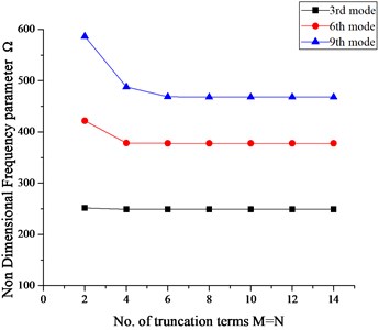
Fig. 5Effect of sector angle on non-dimensional frequency parameter ‘Ω’
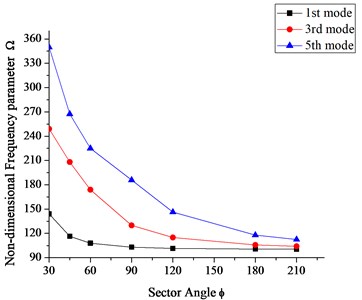
Fig. 6Effect of thickness to radius ratio (h/b) on the frequency parameter
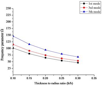
Fig. 7Effect of cutout ratio (a/b) on the frequency parameters
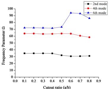
It can be seen in Fig. 5 that for smaller sector angles i.e. , the decrease in the frequency parameters is more as compared to the sector angles greater than . Similarly, in figure 6, 1st, 3rd and 5th mode frequency parameters have been plotted against different thickness to radius ratios () for a fully clamped (CCCC) Mindlin annular sector plate having sector angle and cutout ratio 0.6. It can be observed that with the increase in thickness to radius ratio the frequency parameter always decreases. Similarly, the effect of cutout ratio i.e. inner radius to outer radius () on the frequency parameters for a FSFS mindlin annular sector plate having sector angle , and 0.2 can be seen in Fig. 7.
As mentioned previously, using this method, a Mindlin circular sector plate can also be analyzed easily just by equating the inner radius of Mindlin annular sector plate to zero without modifying the equations or the solution algorithm. Table 8 shows first six non-dimensional frequency parameter along with reference results for Mindlin circular sector plates having inner radius 0.0001, different thickness to radius ratio and sector angles and subjected to simply supported radial edges and clamped circular edge (SCS) boundary condition respectively. A close agreement can be observed in the present values and the reference results.
Table 8First six non-dimensional frequency parameters for SCS Mindlin Circular sector plates (a/b= 0.0001)
Sector angle () | Thickness to radius ratio ) | Method | Mode sequence | |||||
1 | 2 | 3 | 4 | 5 | 6 | |||
0.1 | Present | 91.419 | 148.357 | 205.117 | 208.046 | 278.356 | 281.097 | |
Ref. [8] | 93.450 | 152.630 | 206.900 | 213.080 | 274.650 | 283.190 | ||
0.2 | Present | 66.272 | 98.992 | 131.454 | 131.981 | 161.648 | 163.749 | |
Ref. [8] | 67.933 | 102.560 | 132.860 | 135.610 | 165.680 | 167.820 | ||
0.1 | Present | 31.657 | 60.112 | 71.009 | 92.956 | 110.151 | 118.760 | |
Ref. [8] | 32.205 | 60.637 | 72.221 | 93.450 | 111.320 | 120.450 | ||
0.2 | Present | 26.298 | 46.323 | 53.227 | 67.436 | 77.370 | 82.512 | |
Ref. [8] | 26.993 | 46.906 | 54.466 | 67.933 | 78.582 | 83.903 | ||
0.1 | Present | 20.778 | 31.969 | 45.586 | 54.582 | 60.614 | 71.698 | |
Ref. [8] | 20.223 | 32.205 | 45.773 | 53.859 | 60.637 | 72.221 | ||
0..2 | Present | 17.752 | 26.630 | 36.470 | 42.169 | 46.726 | 53.813 | |
Ref. [8] | 17.773 | 26.993 | 36.758 | 42.393 | 46.906 | 54.466 | ||
0.1 | Present | 19.915 | 28.398 | 39.635 | 51.986 | 52.898 | 65.557 | |
Ref. [8] | 19.489 | 28.599 | 39.786 | 51.998 | 52.416 | 65.091 | ||
0.2 | Present | 16.871 | 23.958 | 32.269 | 40.788 | 40.916 | 49.836 | |
Ref. [8] | 17.092 | 24.293 | 32.519 | 41.067 | 41.195 | 49.859 | ||
All the examples mentioned above are limited to different combinations of classical boundary conditions which are viewed as special case of elastically restrained edges. After verifying the convergence, accuracy and effectiveness of the proposed method for different combinations of classical boundary conditions, the method is further employed here to study the vibration characteristics of Mindlin annular sector and circular sector plates subjected to general elastic boundary conditions.
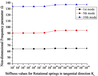
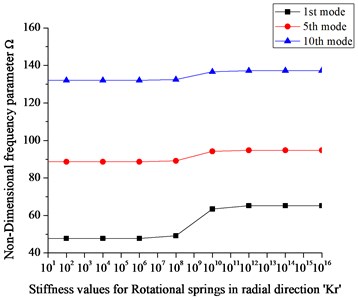
In order to simulate the elastic boundary conditions, it is important to study the effect of restraining springs first on the frequency parameters so that proper value to the restraining springs could be assigned. Fig. 8 shows the effect of restraining springs stiffness on the frequency parameter for Mindlin annular sector plate ( 0.6, 0.2 and 120).
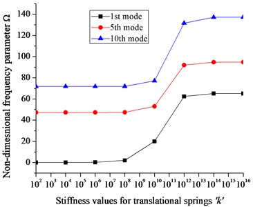
Fig. 8 shows 1st, 5th and 10th mode frequency parameters plotted against the spring stiffnesses by varying the stiffnesses of one group of boundary spring from 0 to 1016 while keeping the stiffnesses of the other group equal to infinite i.e 1016. It can be seen in Fig. 8(a) that the frequency parameter almost remains at a level when the stiffness of the translational spring in direction is less than 108 and greater than 1012 where as other than this range the frequency parameter increases with increasing stiffness values. Similar phenomena can be observed in case of rotational spring stiffness however a slight change in frequency parameter can be observed with in the stiffness range from 108 to 1010. Based on the analysis it can be concluded that stable frequency parameter can be obtained when the stiffnesses for all the restraining springs is more than 1012 or less than 108 and also it is suitable and valid to use the stiffness value 1014 to simulate the infinite stiffness in the numerical calculations since the frequency parameter remain at the same level for values greater than equal to 1014.It can also be concluded that the elastic stiffness range for translational spring is more than the two rotational springs.
Fig. 8a) Effect of translational spring stiffness (k) on Ω, and effect of rotational spring stiffness b) in tangential direction (Kt) on Ω, c) in radial direction (Kr) on Ω
a)
b)
c)
From Fig. 8, an elastic boundary condition can easily be defined with any stiffness value between 108 to 1012. To the author’s best knowledge, no reported results are available in literature for vibration analysis of Mindlin annular sector plates under general elastic boundary conditions. As mentioned earlier the present method can be used to obtain natural frequency parameters for Mindlin annular sector plates under general elastic boundary condition regardless of modifying solution algorithm and procedure.
In order to achieve valuable results for annular sector plates subjected to elastic boundary conditions, we define an elastic restraint ‘E1’having corresponding translational and rotational spring stiffness values 1e8, 0 and 0. Tables 9-11 shows first five natural frequency parameters for Mindlin annular sector plates having different sector angles and thickness-radius ratio () subjected to E1E1E1E1, FE1 FE1 and CE1CE1 boundary conditions where E1E1E1E1, FE1 FE1 and CE1CE1 represents the combination of classic and elastic boundary conditions at edges and as well as 0 and .
Due to unavailability of results in previous literature for these types of boundary conditions (E1E1E1E1, FE1 FE1 and CE1CE1), the comparison has been made with results obtained from ABAQUS. However, we know that the core algorithm of the ABAQUS software is based on the finite element method. Furthermore, the FEM computational accuracy strongly depends on the size of the mesh and the type of element selection. For more accuracy in the higher frequency region and for complex geometries, a highly refined mesh and a higher order finite element is needed. We know that the smaller the mesh size, the greater the number of elements we get for analysis which further requires more computer memory and subsequently a high computational cost. Since the geometry under investigation in this manuscript is a simpler geometry therefore a simple free meshing technique with mesh size 0.005 and S4R (Shell 4 node Reduced Integration) element type has been used which is computationally inexpensive and is considered suitable for this type of geometry and modal analysis. Keeping the mesh size 0.005, the number of elements used in the analysis for annular sector plate having sector angle /3, /2, 2/3 and are 13040, 20080, 29727 and 40240 respectively.
A very good agreement can be observed in Tables 9-11 between the calculated results and the one obtained from ABAQUS. This shows that the present method can be easily applied to classical and elastic type boundary conditions as well as their combination without modifying the solution algorithm and procedure. The results tabulated in Tables 9-11 can be used as a bench mark for future computational methods.
Table 9First five natural frequency parameters for Mindlin Annular sector plates subjected to E1E1E1E1 type elastic boundary conditions (a/b= 0.6)
Sector angle () | Thickness to radius ratio () | Method | Natural frequency modes | ||||
1 | 2 | 3 | 4 | 5 | |||
0.1 | Present | 337.934 | 435.140 | 506.867 | 1520.326 | 1966.903 | |
ABAQUS | 337.690 | 437.350 | 507.130 | 1522.500 | 1969.600 | ||
0.2 | Present | 241.050 | 302.391 | 330.646 | 2587.184 | 3074.622 | |
ABAQUS | 240.970 | 303.960 | 330.420 | 2590.100 | 3080.200 | ||
0.1 | Present | 314.276 | 389.282 | 479.851 | 870.662 | 1294.086 | |
ABAQUS | 313.770 | 390.700 | 480.060 | 872.380 | 1295.400 | ||
0.2 | Present | 225.655 | 274.476 | 318.276 | 1411.322 | 1991.271 | |
ABAQUS | 225.400 | 275.570 | 318.090 | 1412.500 | 1994.500 | ||
0.1 | Present | 300.548 | 361.101 | 440.420 | 703.848 | 884.878 | |
ABAQUS | 301.310 | 364.010 | 443.800 | 707.710 | 901.740 | ||
0..2 | Present | 216.209 | 257.039 | 302.020 | 1032.654 | 1342.753 | |
ABAQUS | 216.710 | 259.290 | 303.580 | 1037.500 | 1374.000 | ||
0.1 | Present | 288.597 | 325.207 | 378.969 | 516.005 | 622.710 | |
ABAQUS | 288.110 | 325.230 | 380.110 | 517.160 | 622.670 | ||
0.2 | Present | 206.659 | 235.054 | 270.651 | 650.104 | 811.858 | |
ABAQUS | 206.290 | 235.350 | 271.530 | 650.900 | 811.980 | ||
Table 10First five natural frequency parameters for Mindlin Annular sector plates subjected to FE1FE1 type elastic boundary conditions (a/b= 0.4)
Sector angle () | Thickness to radius ratio () | Method | Natural frequency | ||||
1 | 2 | 3 | 4 | 5 | |||
0.1 | Present | 119.832 | 264.818 | 319.661 | 1483.220 | 1916.028 | |
ABAQUS | 119.940 | 264.970 | 319.570 | 1484.100 | 1917.400 | ||
0.2 | Present | 83.397 | 180.756 | 222.669 | 2577.428 | 3060.712 | |
ABAQUS | 83.395 | 180.750 | 222.710 | 2580.000 | 3066.200 | ||
0.1 | Present | 57.023 | 251.087 | 267.380 | 786.925 | 1222.649 | |
ABAQUS | 56.935 | 251.210 | 267.440 | 787.520 | 1223.700 | ||
0.2 | Present | 41.696 | 179.512 | 185.090 | 1389.419 | 1971.191 | |
ABAQUS | 40.802 | 179.550 | 184.680 | 1390.300 | 1974.300 | ||
0.1 | Present | 24.833 | 201.973 | 271.669 | 561.948 | 806.253 | |
ABAQUS | 24.039 | 202.070 | 271.430 | 562.430 | 806.550 | ||
0.2 | Present | 18.952 | 149.812 | 189.712 | 995.529 | 1318.058 | |
ABAQUS | 17.523 | 149.840 | 189.290 | 995.930 | 1319.700 | ||
0.1 | Present | 3.867 | 120.269 | 233.439 | 411.437 | 434.108 | |
ABAQUS | 3.856 | 120.260 | 233.370 | 411.390 | 434.060 | ||
0.2 | Present | 3.869 | 105.112 | 171.054 | 610.370 | 758.047 | |
ABAQUS | 0.000 | 105.100 | 170.900 | 610.820 | 758.160 | ||
4. Conclusion
An improved Fourier series method has been presented for vibration analysis of moderately thick annular and circular sector plates with classical and general elastic restraints along its edges. Regardless of the boundary conditions, the displacement function is invariantly expressed as an improved trigonometric series which converges uniformly at an accelerated rate. The efficiency, accuracy and reliability of the present method have been fully demonstrated by various numerical examples for moderately thick annular sector plates having different cutout ratios and sector angles.
Table 11First five natural frequency parameters for Mindlin Annular sector plates subjected to CE1CE1 type elastic boundary conditions (a/b= 0.4)
Sector angle () | Thickness to radius ratio () | Method | Natural frequency modes | ||||
1 | 2 | 3 | 4 | 5 | |||
0.1 | Present | 5161.242 | 5329.372 | 6024.050 | 7500.647 | 9771.648 | |
ABAQUS | 5182.600 | 5349.600 | 6044.000 | 7521.400 | 8046.600 | ||
0.2 | Present | 6628.586 | 6823.656 | 7744.270 | 9710.654 | 12411.918 | |
ABAQUS | 6665.600 | 6859.200 | 7778.100 | 9746.900 | 10565.000 | ||
0.1 | Present | 5167.620 | 5242.262 | 5540.684 | 6140.785 | 7122.635 | |
ABAQUS | 5188.700 | 5261.800 | 5560.000 | 6158.100 | 7141.200 | ||
0.2 | Present | 6633.347 | 6724.016 | 7105.490 | 7936.324 | 9269.663 | |
ABAQUS | 6673.500 | 6762.800 | 7142.300 | 7970.700 | 9306.600 | ||
0.1 | Present | 5171.158 | 5212.374 | 5378.060 | 5694.631 | 6205.673 | |
ABAQUS | 5191.900 | 5231.300 | 5397.000 | 5711.500 | 6222.000 | ||
0..2 | Present | 6636.080 | 6687.398 | 6895.770 | 7327.756 | 8047.005 | |
ABAQUS | 6676.100 | 6726.100 | 6933.100 | 7362.200 | 8080.800 | ||
0.1 | Present | 5175.030 | 5192.529 | 5265.762 | 5397.220 | 5599.831 | |
ABAQUS | 5195.000 | 5210.600 | 5284.500 | 5414.600 | 5616.400 | ||
0.2 | Present | 6639.126 | 6661.568 | 6752.481 | 6926.255 | 7207.997 | |
ABAQUS | 6678.800 | 6699.900 | 6790.300 | 6961.700 | 7241.800 | ||
The effect of sector angle, thickness to radius ratio and restraining springs on the frequency parameters has been discussed. The present method is also employed to study the vibration analysis of moderately thick circular sector plates without modifying the solution procedure. Results for moderately thick annular sector plates under general elastic boundary conditions for various thicknesses to radius ratio and sector angle are presented which can serve as a bench mark for future computational methods. The accuracy of the results has been verified by comparing it with those available in literature and with ABAQUS. An excellent agreement is observed between the results obtained using the present method and with those available in literature. Keeping in view the accuracy and fast convergence behavior this method can easily be further extended to study the vibration analysis of various built up structures without modifying the solution algorithm and procedure.
References
-
Guruswamy P., Yang T. Y. A sector element for dynamic analysis of thick plates. Journal of Sound and Vibration, Vol. 62, 1979, p. 505-516.
-
Soni S. R., Amba Rao C. L. On radially symmetric vibrations of orthotropic non uniform disks including shear deformation. Journal of Sound and Vibration, Vol. 42, 1975, p. 57-63.
-
Liew K. M., Xiang Y., Wang C. M., Kitipornchai S. Flexural vibration of shear deformable circular and annular plates on ring supports. Computer Methods in Applied Mechanics and Engineering, Vol. 110, 1993, p. 301-315.
-
Liew K. M., Xiang Y., Kitipornchai S., Wang C. M. Buckling and vibration of annular Mindlin plates with internal concentric ring supports subject to in-plane radial pressure. Journal of Sound and Vibration, Vol. 177, Issue 5, 1994, p. 689-707.
-
Cheung M. S., Chan M. Y. T. Static and dynamic analysis of thin and thick sectorial plates by the finite strip method. Computers and Structures, Vol. 14, 1981, p. 79-88.
-
Srinivasan R. S., Thiruvenkatachari V. Free vibration of transverse isotropic annular sector Mindlin plates. Journal of Sound and Vibration, Vol. 101, 1985, p. 193-210.
-
Mizusawa T. Vibration of thick annular sector plates using semi analytical methods. Journal of Sound and Vibration, Vol. 150, 1991, p. 245-259.
-
Liu F. L., Liew K. M. Free vibration analysis of Mindlin sector plates: numerical solutions by differential quadrature methods. Computer Methods in Applied Mechanics and Engineering, Vol. 177, 1999, p. 77-92.
-
Liew K. M., Liu F. L. Differential quadrature method for free vibrations of shear deformable annular sector plates. Journal of Sound and Vibrations, Vol. 230, Issue 2, 2000, p. 335-356.
-
Wu T. Y., Liu G. R. Free vibration analysis of circular plates with variable thickness by the generalized differential quadrature rule. International Journal of Solid and Structures, Vol. 38, 2001, p. 7967-7980.
-
Xiang Y., Zhang L. Free vibration analysis of stepped circular Mindlin plates. Journal of Sound and Vibration, Vol. 280, 2005, p. 633-655.
-
So J., Leissa A. W. Three dimensional vibrations of thick circular and annular plates. Journal of Sound and Vibration, Vol. 209, 1998, p. 15-41.
-
Hashemi S. H., Tahir H. R. D., Omidi M. 3-D free vibration analysis of annular plates on Pasternak elastic foundation via p-Ritz method. Journal of Sound and Vibration Vol. 311, 2008, p. 1114-1140.
-
Liew K. M., Yang B. Elasticity solutions for free vibrations of annular plates from three-dimensional analysis. International Journal of Solids and Structure, Vol. 37, 2000, p. 7689-7702.
-
Zhou D., Au F. T. K., Cheung Y. K., Lo S. H. Three dimensional vibration analyses of circular and annular plates via the Chebyshev-Ritz method. International Journal of Solid and Structures Vol. 40, 2003, p. 3089-3105.
-
Farag N. H., Pan J. Modal characteristics of in-plane vibration of circular plates clamped at the outer edge. Journal of Acoustical society of America, Vol. 113, Issue 4, 2003.
-
Karamooz Ravari M. R., Forouzan M. R. Frequency equations for the in-plane vibration of orthotropic circular annular plates. Archives of Applied Mechanics, Vol. 81, 2010, p. 1307-1322.
-
Li W. L. Free vibrations of beams with general boundary conditions. Journal of Sound and Vibration, Vol. 237, 2000, p. 709-725.
-
Li W. L. Comparison of Fourier sine and cosine series expansions for beams with arbitrary boundary conditions. Journal of Sound and Vibration, Vol. 255, Issue 1, 2002, p. 185-194.
-
Li W. L., Bonilha M. W., Xiao J. Vibrations of two beams elastically coupled together at an arbitrary angle. Acta Mechanica Solida Sinica, Vol. 25, 2012, p. 61-72.
-
Li W. L. Vibration analysis of rectangular plates with general elastic boundary supports. Journal of Sound and Vibration, Vol. 273, 2004, p. 619-635.
-
Li W. L., Zhang X., Du J., Liu Z. An exact series solution for the transverse vibration of rectangular plates with general elastic boundary supports. Journal of Sound and Vibration, Vol. 321, 2009, p. 254-269.
-
Shi D. Y., Shi X. J., Li W. L., Wang Q. S. Free transverse vibrations of orthotropic thin rectangular plates with arbitrary elastic edge supports. Journal of Vibroengineering, Vol. 16, 2014, p. 389-398.
-
Shi Xianjie, Shi Dongyan, Qin Zhengrong, Wang Qingshan In-plane vibration analysis of annular plates with arbitrary boundary conditions. The Scientific World Journal, 2014.
-
Shi Xianjie, Kong Lingcheng, Shi Dongyan, Li Wen L. Three-dimensional vibration analysis of annular sector plates with arbitrary thicknesses and Boundary conditions. Inter Noise, Innsbruck, Austria, 2014.
-
Shi Xianjie, Shi Dongyan, Li Wen L., Wang Qingshan A unified method for free vibration of circular, annular and sector plates with arbitrary boundary conditions. Journal of Vibration and Control, 2014.
-
Ma’en Sari S. Free vibration analysis of non-local annular sector Mindlin plates. International Journal of Mechanical Sciences, Vols. 96-97, 2015, p. 25-35.
-
Zhou D., Lo S. H., Cheung Y. K. 3-D vibration analysis of annular sector plates using the Chebyshev-Ritz method. Journal of Sound and Vibration Vol. 320, 2009, p. 421-437.
-
Mcgee O. G., Huang C. S., Leissa A. W. Comprehensive exact solutions for free vibrations of thick annular sectorial plates with simply supported radial edges. International Journal of Mechanical Sciences, Vol. 37, Issue 5, 1995, p. 537-566.
About this article

The authors gratefully acknowledge the financial support from the National Natural Science Foundation of China (No. U1430236) and Natural Science Foundation of Heilongjiang Province of China (No. E2016024).
