Abstract
In this paper an Improved Fourier series method has been employed to study the free vibrations of isotropic homogeneous moderately thick open cylindrical shells with arbitrary subtended angle and general elastic restraints. In this method, regardless of the boundary conditions, each of the displacement components of open shell is invariably expressed as a simple trigonometric series with accelerated and uniform convergence over the solution domain. Distributed elastic restraints are used to specify the elastic boundary conditions along the shell edges and therefore, arbitrary boundary restraints can be achieved by varying the values of spring’s stiffness. All the unknown expansion coefficients are treated as the generalized coordinates and solved using the Rayleigh-Ritz technique. A considerable number of new vibration results for isotropic open cylindrical shells with various geometric parameters and boundary conditions are presented. The effects of boundary stiffness, thickness to radius ratio and subtended angle on the vibration characteristics are also discussed in detail.
1. Introduction
Shell structures are widely used in various engineering applications like submarines, rockets, missile, automobiles and aircrafts etc. In these applications the shell structures may be exposed to various dynamic loads under different boundary conditions. These boundary conditions may be classical, elastic, uniform, non-uniform and/or a combination of these. These dynamic loads under various boundary conditions induce structural vibrations which further results in catastrophic structural failures. Many such incidents have been observed in the history. Due to this reason it is very important to study, design and analyze these structural vibrations for reliable, safe, efficient and lasting structural performance. Based on the geometrical shapes the shell structures may be classified into cylindrical, spherical and conical shells, however in the present manuscript only open cylindrical shells are under consideration which are widely used in various engineering applications.
For any structure, modal analysis is performed to study its vibration characteristics. This modal analysis includes the study of natural frequencies and the corresponding mode shapes. This information is of prime importance in order to suppress the vibrations induced in any structure when it is exposed to dynamic loads or excitations. In case of shell structures there are also other geometric parameters like thickness to length ratio, thickness to radius ratio and subtended angle which plays a prominent role in the vibrations, acoustic and safety analysis of these shell structures. For this reason, a lot of research work has been done on the vibration characteristics of shells and various numerical methods have been developed from time to time and used by researchers to deeply analyze the vibrations of shells. A detailed review of various such methods can be found in the Leissa’s book [1]. To the author’s best knowledge, the literature available related to open cylindrical shells as compared to closed shells is very limited. In this manuscript an effort has been put to study the vibrations characteristics of open cylindrical shells therefore it is necessary to highlight some prominent studies related to open shells.
Initially the study of vibration characteristics of cylindrical shells was limited to shallow shells [2-7]. Later, employing the classical shell theory, Selmane et al. [8], presented a hybrid finite element method for open cylindrical shells. A similar study was performed by Bardell et al. [9]. He used - version of finite element method and studied the isotropic open cylindrical shells. 3-D elasticity approach and three-dimensional displacement based extremum energy principle was used by Lim et al. [10] to perform the modal analysis of open cylindrical shells. Incorporating the effect of shear deformation and rotary inertia, Price et al. [11] did his research on cylindrical pipes and open shells by employing various shell theories. Zhang et al. [12] used wave propagation technique to investigate the natural frequencies and mode shapes for cylindrical panels. Employing virtual work and d’Alembert’s principle followed by predictor-corrector method, Ribeiro [13] investigated the geometrically non-linear vibration characteristics of moderately thick shells.
Using first order shear deformation theory, Kandasamy et al. [14] investigated skewed open cylindrical deep shells. Later in another similar study C. Adam [15], addressed non-linear vibrations of shallow shells with different shear flexibility. Using thin shell theory and discrete singular convolution method, Omer [16] studied the vibration characteristics of laminated conical and cylindrical shells. Similarly, in another study laminated open cylindrical shells were studied by Ribeiro [17] using clamped boundary conditions. Tornabene et al. [18] studied the FGM shell and plate structures using differential quadrature method. In another important research Hadi et.al [19], performed research on shallow cylindrical and delaminated shells for large amplitude vibrations. A 3D higher deformation theory was employed by Khalili et al. [20] to calculate the modal frequencies of circular shells subjected to various classical boundary conditions. Employing Ritz method similar research on different geometrical shell structures subjected to arbitrary boundary conditions were performed by Qatu and Asadi [21]. A lot of other similar important research work on cylindrical shells is given in [22-37].
A very important method previously developed for beams [38] and plates [39] is presently a source of attention for researchers and is currently used for studying the vibration characteristics of shells subjected to general boundary conditions. In this manuscript this method has been employed to study the vibration characteristics of moderately thick isotropic homogeneous open cylindrical shells subjected to general elastic boundary conditions.
2. Theoretical formulation
2.1. Model description
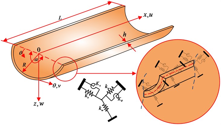
Consider an isotropic homogeneous moderately thick open cylindrical shell having uniform thickness , subtended angle , radius , and length as shown in Fig. 1. A cylindrical coordinate system (, , ) is also shown, in which the coordinate is taken in the axis of the shell panel and and represents the circumferential and radial directions respectively. The middle surface displacements are represented by , and whereas and represents the rotation of transverse normal with respect to and axis respectively.
Three translational springs having stiffnesses (, and ) and two rotational springs having stiffnesses ( and ) are introduced along each edge of the cylindrical shell panel to simulate arbitrary boundary conditions. All the classical sets of boundary conditions can easily be achieved by assigning proper stiffness values to the translational and rotational springs. For instance, a clamped boundary (C) is achieved by simply setting the stiffnesses of the entire springs equal to infinite (which is represented by a very large number, 1014 N/m). Inversely, a free boundary (F) is gained by setting the stiffnesses of the entire springs equal to zero.
Fig. 1Geometry of open shell
2.2. Energy functional of moderately thick open cylindrical shells
Based on first order shear deformation theory for isotropic homogeneous moderately thick cylindrical shells, the displacement components (, and ) of the shell in terms of middle surface displacements can be expressed as:
where , and are the middle surface displacements of the shell in the axial, circumferential and radial directions respectively, and represent the rotations of transverse normal with respect to and -axes and is the time variable. The strain displacement relation for the shell panel in terms of middle surface strains can be expressed as:
where , and represents the middle surface strains and , and represents the curvature changes during deformation for a moderately thick shell panel. For a cylindrical shell panel having constant radius , the middle surface strains and curvature changes are given as:
The transverse shear strains are given by:
According to Hooke’s law the stress strains relations for a moderately thick cylindrical shell are given as:
where , , , is the modulus of elasticity and is the Poisson ratio.
The in-plane force resultant vector, bending and twisting moment resultant vector and transverse shear force resultant vector is given by:
where ‘’ is the shear correction factor i.e. 5/6
The equations relating the force and moment resultants to the strains and curvature changes in the middle surface can be written in matrix form as:
where , and , , 1, 2, 6.
The strain energy of the open circular cylindrical shell is given by:
Substituting Eq. (8) into (9), the strain energy can be expressed as a sum of three parts:
For cylindrical shells:
Similarly, the kinetic energy of the open cylindrical shell is given by:
where is density.
Since three groups of translational springs (, and ) and two groups of rotational springs ( and ) are attached at each edge of the open cylindrical shell to simulate the arbitrary elastic boundary conditions, therefore the potential or strain energy stored in these elastic springs can be expressed as:
After establishing the strain energy and kinetic energy expressions, the Lagrangian expression can be written as:
3. Solution scheme
3.1. Selection of Admissible displacement functions
After establishing the potential energy and kinetic energy expression, the next step is to choose appropriate admissible displacement functions which is of crucial importance in the Rayleigh-Ritz procedure. Generally, for shell problems, the admissible functions are often expressed in terms of beam functions under the same boundary conditions. Thus, a specially customized set of beam functions is required for each type of boundary conditions. Instead of the beam functions, one may also use other forms of admissible functions such as orthogonal polynomials. However, the higher order polynomials tend to become numerically unstable due to the computer round-off errors. This numerical difficulty can be avoided by expressing the displacement functions in the form of a Fourier series expansion because Fourier functions constitute a complete set and exhibit an excellent numerical stability.
In the present study, irrespective of the boundary conditions, each of the displacement function is expressed as a new form of trigonometric expansion with accelerated convergence. Each of displacement and rotation functions of the open cylindrical shell is expanded as:
where:
The sine terms in the Eq. (17) are introduced to overcome the potential discontinuities of the displacement function, along the edges of the shell, when it is periodically extended and sought in the form of trigonometric series expansion. As a result, the Gibbs effect can be eliminated and the convergence of the series expansion can be substantially improved.
3.2. Determination of expansion coefficients
After establishing energy expressions and selecting proper admissible displacement functions, the next step is to find the expansion coefficients in the assumed displacement series. This can be achieved by substituting the assumed displacement fields Eq. (17) in the Eq. (10), (14) and (15) and then minimizing Eq. (16) against all the unknown series expansion coefficients i.e.:
After minimizing the Langrangian against all unknown series expansion coefficients as shown in Eq. (18), we will obtain a series of linear algebraic expressions which can be further expressed in matrix form as:
where is a vector which contains all the unknown series expansion coefficients, and are the stiffness and mass matrices, respectively. , and are expressed as:
For conciseness, the detailed expressions for the stiffness and mass matrices are not shown here.
3.3. Determination of eigen values and eigen vectors
After establishing Eq. (19), the eigenvalues (or natural frequencies) and eigenvectors of moderately thick open cylindrical shell can now be easily and directly determined from solving a standard matrix eigenvalue problem Eq. (19). In the current work, the authors have used MATLAB software to obtain eigen values (natural frequencies) and corresponding eigen vectors. For a given natural frequency, the corresponding eigenvector actually contains the series expansion coefficients which can be used to construct the physical mode shape based on Eq. (17). Although this investigation is focused on the free vibration of open cylindrical shells, the response of the shell panel to an applied load can also be easily obtained by considering the work done by this load in the Lagrangian, eventually leading to a force term on the right side of Eq. (19).
4. Results and discussion
In practical engineering, the study of structure response, when it is subjected to static or dynamic loads is of critical importance. One of such studies is the modal analysis and testing. The modal analysis of any structure includes the identification of resonant frequencies which are subsequently quantified to avoid well known resonance phenomena. In order to find these modes of vibrations or resonant frequencies accurately, researchers have developed various analytical methods for different boundary conditions. For any structure the modes of vibration are highly dependent upon the material properties and boundary conditions. Each mode of vibration is defined by a natural (modal or resonant) frequency, modal damping, and a mode shape. If there is a slight change in material properties or boundary conditions of a structure, its modes of vibration will also change. Since in real scenarios, the material properties and boundary conditions of any structure may vary therefore it is of prime importance to study or estimate these natural frequencies for any change in material properties as well as boundary conditions.
In this section a systematic comparison of the results obtained using the present method and those obtained from ABAQUS is carried out to verify the accuracy, reliability and feasibility of the present method. First of all, the convergence study of the present method is performed. Convergence study is important to check the rationality of hypothetical admissible functions of the displacement fields and also to determine the proper truncated numbers in the calculations to follow. Therefore, for different values of and (number of truncation terms) results are calculated for a completely clamped moderately thick open cylindrical shell panel having parameters 60°, 0.1, 2. For convenience, the four-letter string ‘CCCC’ has been used to refer to clamped boundary condition at edges 0, 0, and , respectively. The clamped boundary condition is easily achieved by assigning a very high stiffness value i.e 1e14 to the boundary springs. Similarly, free boundary conditions can be achieved by assigning zero stiffness value to the restraining springs. In calculations to follow the symbol , and will be used to denote the simply supported, free and elastic boundary restraints. For different no. of truncation terms, Table 1 shows first six frequencies (Hz) for open cylindrical shell panel subjected to CCCC boundary conditions.
Table 1First six frequencies (Hz) for completely clamped open cylindrical shell panel (α= 60°, h/R= 0.1, l/R= 2)
Mode sequence | ||||||
1 | 2 | 3 | 4 | 5 | 6 | |
2 | 879.547 | 1112.311 | 1463.763 | 1671.980 | 2021.887 | 2140.287 |
4 | 877.588 | 991.404 | 1227.954 | 1228.916 | 1411.978 | 1692.215 |
6 | 877.328 | 988.366 | 1210.706 | 1222.908 | 1402.000 | 1548.622 |
8 | 877.251 | 987.671 | 1208.433 | 1221.810 | 1399.761 | 1540.250 |
10 | 877.223 | 987.445 | 1207.782 | 1221.501 | 1399.045 | 1538.153 |
12 | 877.210 | 987.354 | 1207.536 | 1221.390 | 1398.764 | 1537.416 |
14 | 877.204 | 987.312 | 1207.426 | 1221.342 | 1398.635 | 1537.105 |
16 | 877.201 | 987.291 | 1207.372 | 1221.319 | 1398.569 | 1536.956 |
18 | 877.199 | 987.279 | 1207.342 | 1221.307 | 1398.533 | 1536.878 |
20 | 877.198 | 987.271 | 1207.325 | 1221.300 | 1398.512 | 1536.834 |
ABAQUS | 877.340 | 987.040 | 1207.100 | 1222.700 | 1398.600 | 1537.300 |
Table 2First six frequencies (Hz) for open cylindrical shell panel (α= 270°, h/R= 0.2, l/R= 2) subjected to CFCF boundary conditions
Mode sequence | ||||||
1 | 2 | 3 | 4 | 5 | 6 | |
2 | 392.809 | 399.278 | 515.197 | 606.723 | 752.915 | 918.837 |
4 | 356.415 | 363.707 | 500.894 | 517.999 | 600.070 | 741.259 |
6 | 338.981 | 345.826 | 488.791 | 495.970 | 578.042 | 605.890 |
8 | 336.239 | 336.714 | 477.231 | 485.121 | 573.300 | 603.493 |
10 | 336.234 | 336.681 | 477.000 | 484.965 | 571.963 | 602.551 |
12 | 336.231 | 336.519 | 476.880 | 484.739 | 569.786 | 598.987 |
14 | 336.227 | 336.452 | 476.808 | 483.984 | 568.681 | 598.606 |
16 | 336.210 | 336.423 | 476.761 | 483.874 | 568.614 | 597.998 |
18 | 336.197 | 336.409 | 476.729 | 483.793 | 568.569 | 597.745 |
20 | 336.189 | 336.316 | 476.706 | 483.735 | 568.536 | 597.610 |
It can be seen that the frequency parameter converges very quickly for small number of truncation terms. Furthermore, the results are also in close agreement with those obtained from ABAQUS. Similarly, Table 2 gives first five frequency parameter (Hz) for cylindrical shell panel having geometric parameters (270°, 0.2, 2) and subjected to CFCF boundary conditions.
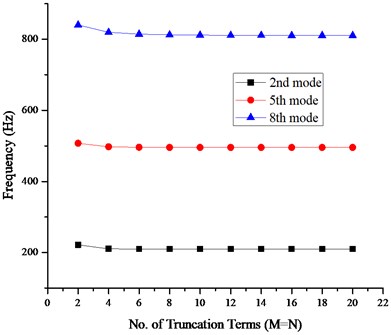
A fast convergence and close agreement with the results obtained from ABAQUS can be seen. Furthermore, the fast convergence of the frequencies can be observed in Fig. 2 which shows convergence of 2nd, 5th and 8th mode frequencies of cylindrical shell panel (60°, 0.1, 2) subjected to FFFF boundary conditions and using different number of truncation terms.
It can be observed from table 1 that when the truncated terms change from 10 to 12, the difference of the frequency parameters does not exceed 0.045 % for the worst case, which is acceptable. More accurate results may be obtained by further truncated numbers, but the computational cost will be increased. Therefore, for the sake of both accuracy and computational cost, the truncated number of the displacement expressions will be uniformly selected as 12 in all the following numerical calculations.
Fig. 2Convergence pattern of frequency parameters with no. of terms (M=N)
After studying the convergence of the present method, the accuracy of the method is verified by applying it on cylindrical shell panels subjected to various combinations of classical boundary conditions. The first four non-dimensional frequency parameters for a moderately thick cylindrical shell panel having geometric parameters (180°, 0.1, 2) subjected to various combinations of classical boundary conditions are presented in Table 3. A good agreement can be observed between the calculated results and those obtained from ABAQUS.
Table 3First four non-dimensional frequency parameters Ω=ω×Rρ(1-μ2)*E-1 for cylindrical shell panel (α= 180°, h/R= 0.1, l/R= 2) subjected to various boundary conditions
BC | Methods | Mode sequence | |||
1 | 2 | 3 | 4 | ||
CFCF | Present | 0.2458 | 0.2541 | 0.4127 | 0.4656 |
ABAQUS | 0.2448 | 0.2518 | 0.4113 | 0.4655 | |
CFFF | Present | 0.0877 | 0.0891 | 0.1872 | 0.1976 |
ABAQUS | 0.0861 | 0.0887 | 0.1868 | 0.1959 | |
FFCC | Present | 0.0937 | 0.1885 | 0.2876 | 0.3014 |
ABAQUS | 0.0906 | 0.1867 | 0.2852 | 0.2951 | |
After verifying the accuracy of the present method for various combinations of classical boundary conditions, it is important to study the effect of boundary spring stiffnesses on the frequency parameters. Figs. 3 and 4 shows the variation of frequency for 7th, 8th and 9th mode respectively plotted against the spring stiffnesses by varying the stiffnesses of one group of boundary springs from 0 to 1014 while keeping the stiffnesses of the other group equal to infinite i.e. 1014.
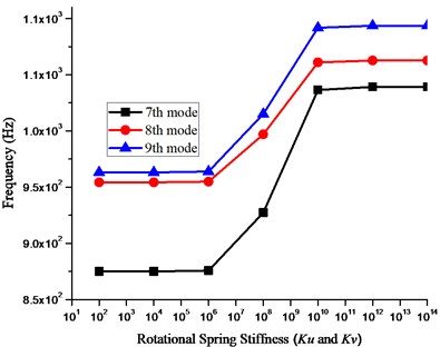
It can be seen in Fig. 3 that the frequency parameter almost remains at a level when the stiffness of the translational springs in , and directions is less than 108 and greater than 1012 where as other than this range the frequency parameter increases with increasing stiffness values. Similar phenomena can be observed in Fig. 4 which shows the variation in frequency parameter with increasing stiffness values for rotational springs. It can be observed from figures that the influential range for translational and rotational springs is 108 to 1012 and 106 to 1010 respectively. Within this range the frequency parameter increases with increasing stiffness values however before and after this influential range the frequency parameters remain at a level. Based on the analysis it can be concluded that stable frequency parameter can be obtained when the stiffnesses for all the restraining springs is more than 1012 or less than 106 and also it is also suitable and valid to use the stiffness value 1014 to simulate the infinite stiffness in the numerical calculations since the frequency parameter remain at the same level for values greater than equal to 1012. Also, an elastic boundary condition can also be easily defined with any stiffness value between 106 to 1012.
Fig. 3Effect of translational springs stiffness (ku, kv and kw) on the frequency parameter
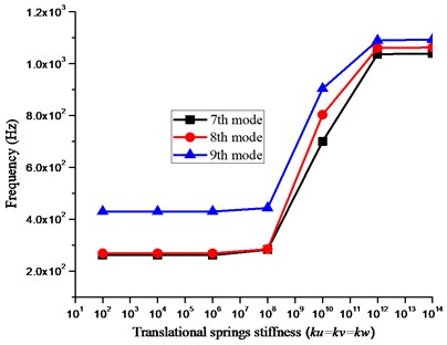
Fig. 4Effect of rotational springs stiffness (Kx and Kθ) on the frequency parameter
As mentioned earlier the present method can be used to obtain natural frequency parameters for moderately thick open cylindrical shell under general elastic boundary condition regardless of modifying solution algorithm and procedure. The arbitrary boundary conditions including the classical and elastic boundary restraints can easily be achieved by assigning proper stiffness values to the restraining springs as shown in Table 4 where E1 and E2 represents the two different types of elastic restraints having different stiffness values.
Table 4Corresponding spring’s stiffnesses for different types of boundary conditions.
BC | or | or | ||||||||
F | 0 | 0 | 0 | 0 | 0 | 0 | 0 | 0 | 0 | 0 |
C | 1e14 | 1e14 | 1e14 | 1e14 | 1e14 | 1e14 | 1e14 | 1e14 | 1e14 | 1e14 |
S | 0 | 1e14 | 1e14 | 0 | 1e14 | 1e14 | 0 | 1e14 | 1e14 | 0 |
E1 | 1e8 | 1e14 | 1e14 | 1e14 | 1e14 | 1e8 | 1e14 | 1e14 | 1e14 | 1e14 |
E2 | 1e14 | 1e8 | 1e14 | 1e14 | 1e14 | 1e14 | 1e8 | 1e14 | 1e14 | 1e14 |
Next, we calculate the frequency parameter for open cylindrical shells using different combinations of classical and elastic boundary restraints. Table 5, 6 and 7 shows the frequency parameters for open cylindrical shell panels having different subtended angles, thickness to radius ratio and subjected to various combinations of classical and elastic boundary conditions.
It can be observed that all the frequencies mentioned in table 5, 6 and 7 are in close agreement with those obtained from ABAQUS. The maximum error for the worst case in the Table 5, 6 and 7 is 0.17 % which is acceptable.
At present, most of the existing techniques available so far to estimate the natural or resonant frequencies are limited to classical boundary conditions (clamped, free, simply supported etc.), however in practical engineering applications the structures are not always subjected to classical boundary conditions rather they may be subjected to elastic boundary conditions. In the present manuscript, the method presented not only helps to accurately estimate these natural frequencies of cylindrical shells subjected to different sets of classical boundary conditions but also accurately predicts these frequencies when such structures are subjected to general elastic boundary conditions. Furthermore, the presented results give an insight of the modes of vibration of these structures having different material properties and subjected to elastic boundary conditions. Moreover, another important contribution of this technique is that this method does not require any changes in procedure or solution algorithms to accommodate different geometries, material properties or boundary conditions. The same solution algorithm or procedure can be used to estimate natural frequencies for different materials and boundary conditions. Different boundary conditions (classical, elastic, uniform & non-uniform) can easily be achieved by simply changing the stiffnesses of the translational and rotational springs attached at the boundaries or edges of the shell structure.
Table 5First four frequencies (Hz) for open cylindrical shell panel (α= 60°, l/R= 2) subjected to different boundary conditions
BC | Methods | Mode sequence | ||||
1 | 2 | 3 | 4 | |||
E1E1E1E1 | 0.1 | Present | 78.816 | 836.356 | 963.911 | 1191.668 |
ABAQUS | 78.704 | 836.160 | 963.160 | 1190.700 | ||
% Error | 0.14 | 0.02 | 0.08 | 0.08 | ||
0.2 | Present | 55.704 | 1080.569 | 1326.075 | 1405.296 | |
ABAQUS | 55.670 | 1080.100 | 1325.000 | 1405.000 | ||
% Error | 0.06 | 0.04 | 0.08 | 0.02 | ||
CE1CE1 | 0.1 | Present | 870.575 | 955.476 | 1195.536 | 1220.768 |
ABAQUS | 870.380 | 954.690 | 1194.700 | 1220.300 | ||
% Error | 0.02 | 0.08 | 0.06 | 0.03 | ||
0.2 | Present | 1130.947 | 1262.642 | 1432.718 | 1712.324 | |
ABAQUS | 1130.800 | 1262.200 | 1432.500 | 1712.100 | ||
% Error | 0.01 | 0.04 | 0.02 | 0.01 | ||
FE1FE1 | 0.1 | Present | 55.660 | 808.238 | 830.808 | 884.843 |
ABAQUS | 55.654 | 807.400 | 830.020 | 884.020 | ||
% Error | 0.01 | 0.1 | 0.09 | 0.09 | ||
0.2 | Present | 39.395 | 1027.752 | 1070.862 | 1166.300 | |
ABAQUS | 39.365 | 1027.100 | 1070.400 | 1165.800 | ||
% Error | 0.07 | 0.06 | 0.04 | 0.04 | ||
Table 6First four frequencies (Hz) for open cylindrical shell panel (α= 90°, l/R= 2) subjected to different boundary conditions
BC | Methods | Mode sequence | ||||
1 | 2 | 3 | 4 | |||
CE1CF | 0.1 | Present | 222.246 | 440.265 | 474.896 | 664.259 |
ABAQUS | 221.870 | 439.810 | 474.620 | 663.870 | ||
% Error | 0.17 | 0.10 | 0.06 | 0.06 | ||
0.2 | Present | 349.143 | 591.131 | 755.025 | 1024.495 | |
ABAQUS | 349.110 | 590.980 | 754.900 | 1024.100 | ||
% Error | 0.01 | 0.02 | 0.02 | 0.04 | ||
CE2CE2 | 0.1 | Present | 425.665 | 539.988 | 731.036 | 750.295 |
ABAQUS | 425.530 | 539.870 | 730.790 | 750.100 | ||
% Error | 0.03 | 0.02 | 0.03 | 0.03 | ||
0.2 | Present | 575.058 | 657.481 | 1012.780 | 1091.955 | |
ABAQUS | 574.800 | 657.200 | 1012.500 | 1091.200 | ||
% Error | 0.04 | 0.04 | 0.03 | 0.07 | ||
FE1FE1 | 0.1 | Present | 45.480 | 506.710 | 522.305 | 657.038 |
ABAQUS | 45.425 | 506.650 | 522.240 | 656.910 | ||
% Error | 0.12 | 0.01 | 0.01 | 0.02 | ||
0.2 | Present | 32.143 | 727.394 | 755.393 | 780.742 | |
ABAQUS | 32.136 | 727.290 | 755.250 | 780.560 | ||
% Error | 0.05 | 0.01 | 0.02 | 0.02 | ||
Table 7First four frequencies (Hz) for open cylindrical shell panel (α= 270°, l/R= 2) subjected to different boundary conditions
BC | Methods | Mode sequence | ||||
1 | 2 | 3 | 4 | |||
E1FE1F | 0.1 | Present | 29.773 | 193.010 | 196.105 | 316.912 |
ABAQUS | 29.760 | 192.970 | 196.070 | 316.860 | ||
% Error | 0.04 | 0.02 | 0.02 | 0.02 | ||
0.2 | Present | 21.053 | 309.710 | 314.003 | 423.101 | |
ABAQUS | 21.046 | 309.650 | 313.950 | 423.050 | ||
% Error | 0.03 | 0.02 | 0.02 | 0.01 | ||
CE2CE2 | 0.1 | Present | 371.725 | 399.433 | 449.635 | 550.224 |
ABAQUS | 371.660 | 399.380 | 449.590 | 550.090 | ||
% Error | 0.02 | 0.01 | 0.01 | 0.02 | ||
0.2 | Present | 483.725 | 544.132 | 587.706 | 739.569 | |
ABAQUS | 483.690 | 544.080 | 587.640 | 739.410 | ||
% Error | 0.01 | 0.01 | 0.01 | 0.02 | ||
CE1CF | 0.1 | Present | 215.061 | 364.871 | 413.932 | 461.280 |
ABAQUS | 215.000 | 364.830 | 413.890 | 461.240 | ||
% Error | 0.03 | 0.01 | 0.01 | 0.01 | ||
0.2 | Present | 336.439 | 486.840 | 557.422 | 645.701 | |
ABAQUS | 336.400 | 486.780 | 557.310 | 645.560 | ||
% Error | 0.01 | 0.01 | 0.02 | 0.02 | ||
5. Conclusions
In this manuscript, an Improved Fourier series method previously developed for beams and plates has been employed to study the vibration characteristics of moderately thick isotropic homogeneous open cylindrical shells subjected to arbitrary elastic boundary conditions. Distributed elastic restraints have been used along the shell edges to achieve the elastic boundary restraints. Irrespective of the boundary conditions, all the displacement components have been presented in the form of simple trigonometric series with accelerated and uniform convergence. All the unknown expansion coefficients have been obtained using Rayleigh-Ritz technique. The efficiency, accuracy and reliability of the present method have been fully demonstrated by various numerical examples. All the results obtained have been found in close agreement with those obtained from ABAQUS. The effects of spring stiffnesses, thickness to radius ratio and subtended angle on the vibration characteristics have also been highlighted. In comparison with most existing techniques, the present method does not require any inconvenient formulation or procedural modifications to accommodate different boundary conditions or geometrical shapes. Furthermore, this method can easily be extended to study vibration analysis of different shell plate combinations.
References
-
Leissa A. W. Vibrations of Shells. National Aeronautics and Space Administration, Washington DC, 1973.
-
Leissa A. W., Narita Y. Vibrations of completely free shallow shells of rectangular planform. Journal of Sound and Vibration, Vol. 96, 1984, p. 207-218.
-
Qatu M. S., Leissa A. W. Free vibrations of completely free doubly curved laminated composite shallow shells. Journal of Sound and Vibration, Vol. 151, 1991, p. 9-29.
-
Mecitoglu Z., Dokmeci M. C. Free vibration of a thin, stiffened, cylindrical shallow shell. AIAA Journal, Vol. 30, 1992, p. 848-850.
-
Qatu M. S., Asadi E. Vibration of doubly curved shallow shells with arbitrary boundaries. Applied Acoustics, Vol. 73, 2012, p. 21-27.
-
Lim C. W., Liew K. M. A higher order theory for vibration of shear deformable cylindrical shallow shells. International Journal of Mechanical Sciences, Vol. 37, 1995, p. 277-295.
-
Liew K. M., Lim C. W. A Ritz vibration analysis of doubly-curved rectangular shallow shells using a refined first-order theory. Computational Methods in Applied Mechanics and Engineering, Vol. 127, 1995, p. 145-162.
-
Selmane A., Lakis A. A. Dynamic analysis of anisotropic open cylindrical shells. Computers and Structures, Vol. 62, Issue 1, 1997, p. 1-12.
-
Bardell N. S., Dunsdon J. M., Langley R. S. On the free vibration of completely free, open, cylindrically curved isotropic shell panels. Journal of Sound and Vibration, Vol. 207, Issue 5, 1997, p. 647-669.
-
Lim C. W., Liew K. M., Kitipornchai S. Vibration of open cylindrical shells – a three-dimensional elasticity approach. Journal of Acoustical Society of America, Vol. 104, 1998.
-
Price N. M., Liu M., Eatock Taylor R. Vibrations of cylindrical pipes and open shells. Journal of Sound and Vibration, Vol. 218, 1998, p. 361-387.
-
Zhang X. M., Liu G. R., Lam K. Y. Frequency analysis of cylindrical panels using a wave propagation approach. Applied Acoustics, Vol. 62, Issue 5, 2001, p. 527-543.
-
Ribeiro Pedro A hierarchical finite element for geometrically non-linear vibration of doubly curved, moderately thick isotropic shallow shells. International Journal for Numerical methods in Engineering, Vol. 56, 2003, p. 715-738.
-
Kandasamy S., Singh A. V. Free vibration analysis of skewed open circular cylindrical shells. Journal of Sound and Vibration, Vol. 290, Issue 3, 2006, p. 1100-1118.
-
Adam Christoph Moderately large vibrations of doubly curved shallow open shells composed of thick layers. Journal of Sound and Vibration, Vol. 299, 2007, p. 854-868.
-
Civalek Ömer Numerical analysis of free vibrations of laminated composite conical and cylindrical shells: discrete singular convolution (DSC) approach. Journal of Computational and Applied Mathematics, Vol. 205, 2007, p. 251-271.
-
Ribeiro Pedro On the influence of membrane inertia and shear deformation on the geometrically non-linear vibrations of open, cylindrical, laminated clamped shells. Composites Science and Technology, Vol. 69, 2009, p. 176-185.
-
Tornabene Francesco, Viola Erasmo, Inman Daniel J. 2-D differential quadrature solution for vibration analysis of functionally graded conical, cylindrical shell and annular plate structures. Journal of Sound and Vibration, Vol. 328, 2009, p. 259-290.
-
Nabil Hassan Hadi, Kayser Aziz Ameen Nonlinear free vibrations of cylindrical shells with delamination using high order shear deformation theory – a finite element approach. American Journal of Scientific and Industrial Research, Vol. 2, 2011, p. 251-277.
-
Khalili S. M. R., Davar A., Fard Malekzadeh K. Free vibration analysis of homogeneous isotropic circular cylindrical shells based on a new three-dimensional refined higher-order theory. International Journal of Mechanical Sciences, Vol. 56, 2012, p. 1-25.
-
Qatu M. S., Asadi E. Vibration of doubly curved shallow shells with arbitrary boundaries. Applied Acoustics, Vol. 73, Issue 1, 2012, p. 21-27.
-
Dai Lu, Yang Tiejun, Li W. L., Du Jingtao, Jin Guoyong Dynamic analysis of circular cylindrical shells with general boundary conditions using modified Fourier series method. Journal of Vibration and Acoustics, Vol. 134, 2012.
-
Farshidianfar Anooshiravan, Oliazadeh Pouria Free vibration analysis of circular cylindrical shells: comparison of different shell theories. International Journal of Mechanics and Applications, Vol. 2, 2012, p. 74-80.
-
Zhou Haijun, Li Wanyou, Lv Binglin, Li W. L. Free vibrations of cylindrical shells with elastic-support boundary conditions. Applied Acoustics, Vol. 73, 2012, p. 751-756.
-
Chen Yuehua, Jin Guoyong, Liu Zhigang Free vibration analysis of circular cylindrical shell with non-uniform elastic boundary constraints. International Journal of Mechanical Sciences, Vol. 74, 2013, p. 120-132.
-
Tornabene F., Viola E., Fantuzzi N. General higher-order equivalent single layer theory for free vibrations of doubly curved laminated composite shells and panels. Composite Structures, Vol. 104, 2013, p. 94-117.
-
Fazzolari F. A., Carrera E. Advances in the Ritz formulation for free vibration response of doubly-curved anisotropic laminated composite shallow and deep shells. Composite Structures, Vol. 101, 2013, p. 111-128.
-
Jin Guoyong, Ye Tiangui, Ma Xianglong, Chen Yuehua, Su Zhu, Xie Xiang A unified approach for the vibration analysis of moderately thick composite laminated cylindrical shells with arbitrary boundary conditions. International Journal of Mechanical Sciences, Vol. 75, 2013, p. 357-376.
-
Jin Guoyong, Ye Tiangui, Chen Yuehua, Su Zhu, Yan Yuquan An exact solution for the free vibration analysis of laminated composite cylindrical shells with general elastic boundary conditions. Composite Structures, Vol. 106, 2013, p. 114-127.
-
Qu Yegao, Hua Hongxing, Meng Guang A domain decomposition approach for vibration analysis of isotropic and composite cylindrical shells with arbitrary boundaries. Composite Structures, Vol. 95, 2013, p. 307-321.
-
Xie Xiang, Jin Guoyong, Liu Zhigang Free vibration analysis of cylindrical shells using the Haar wavelet method. International Journal of Mechanical Sciences, Vol. 77, 2013, p. 47-56.
-
Xing Yufeng, Liu Bo, Xu Tengfei Exact solutions for free vibration of circular cylindrical shells with classical boundary conditions. International Journal of Mechanical Sciences, Vol. 75, 2013, p. 178-188.
-
Ye Tiangui, Jin Guoyong, Su Zhu, Jia Xingzhao A unified Chebyshev–Ritz formulation for vibration analysis of composite laminated deep open shells with arbitrary boundary conditions. Archive of Applied Mechanics, Vol. 84, 2014, p. 441-471.
-
Su Zhu, Jin Guoyong, Ye Tiangui Free vibration analysis of moderately thick functionally graded open shells with general boundary conditions. Composite Structures, 2014.
-
Ye Tiangui, Jin Guoyong, Chen Yuehua, Shi Shuangxia A unified formulation for vibration analysis of open shells with arbitrary boundary conditions. International Journal of Mechanical Sciences, Vol. 81, 2014, p. 42-59.
-
Tornabene F., Brischetto S., Fantuzzi N., Viola E. Numerical and exact models for free vibration analysis of cylindrical and spherical shell panels. Composites Part B, Vol. 81, 2015, p. 231-250.
-
Shi Dongyan, Yunke Zhao, Wang Qingshan, Teng Xiaoyan, Pang Fuzhen A unified spectro-geometric-ritz method for vibration analysis of open and closed shells with arbitrary boundary conditions. Journal of Shock and Vibration, 2016.
-
Li W. L. Free vibrations of beams with general boundary conditions. Journal of Sound and Vibration, Vol. 237, Issue 4, 2000, p. 709-725.
-
Li W. L. Vibration analysis of rectangular plates with general elastic boundary supports. Journal of Sound and Vibration, Vol. 273, Issue 3, 2004, p. 619-635.
Cited by
About this article

The authors gratefully acknowledge the financial support from the National Natural Science Foundation of China (No. U1430236) and Natural Science Foundation of Heilongjiang Province of China (No. E2016024)
