Abstract
This paper presents the fluid structure of the third passive vibration isolation element inerter. The fluid inerter ideally has the same characteristic that the force applying to the two terminals is proportional to the relative acceleration as the ball-screw inerter and rack-and-pinion inerter. An optimized nonlinear model of the fluid inerter is introduced, and the effect of nonlinearities compromising friction, oil density and viscosity of the fluid are discussed and analyzed. Simulations show that the friction has a great effect on the dynamic performance of fluid inerter in low frequency and the influence of the viscosity is not negligible. The damping force and the inertia force will become larger with the increase of the frequency and the inertia force will become more and more apparent in higher frequency. Furthermore, experiments are carried out to test the effectiveness of the fluid inerter. Results show that the optimized nonlinear model of the fluid inerter is deemed effective.
1. Introduction
As a new mechanical circuit element, inerter was firstly proposed in [1] and defined as a two-terminal element just like the spring and damper. It was called the missing circuit element in [2] because the force applying to the device is proportional to the relative acceleration of the two terminals. Then, the mass element is replaced by the inerter in the ‘force-current’ analogy so that the passive network impedance can be realized by the combination of inerter, spring and damper [3, 4]. Also, the traditional mechanical spring-damper network performance can be improved by the inclusion of the inerter. In [5, 6], the DVA theory is used in vibration reduction of car body and structure vibration control based on the mass-spring-damper circuit. In [7], a novel structure called the tuned mass-damper-inerter (TMDI) was proposed based on the new mechanical circuits compromising inerter, spring and damper. Conclusions showed that the incorporation of the inerter in the proposed TMDI configuration can either replace part of the TMD vibrating mass to achieve lightweight passive vibration control solutions, or improve the performance of the classical TMD for a given TMD mass. Furthermore, the influence of inerter on the natural frequencies of vibration systems was investigated in [8] to demonstrate that the inerter can reduce the natural frequencies of the vibration system.
Inerter has a superior vibration isolation performance and has been widely used in vehicle suspension [9-12], train suspension [13, 14], building suspension [15] and the steering compensation for high-performance motorcycles [16].
The earliest types of inerter are the rack-and-pinion inerter and ball-screw inerter introduced in [17, 18]. Experiments were also carried out to verify the effectiveness of the mechanical inerter. Then, the impact of inerter nonlinearities on vehicle suspension control was analyzed in [19, 20] to demonstrate that the suspension performance is in generally degraded by inerter nonlinearities but it is still better than the traditional suspensions. In 2011, a new type of hydraulic inerter was proposed in [21]. There is a similarity that the inertia effects are all achieved by means of driving the flywheel with a motion conversion mechanism among the ball-screw inerter, rack-and-pinion inerter and the hydraulic inerter, which may limit the use of it. In [22], a new fluid inerter was invented and can be readily adapted to implement various passive network layouts in [23]. Besides, variable orifices and valves can be included to provide series or parallel damping and a look-up table was established during the study of the damping force. However, the nonlinear model of the fluid inerter was not introduced and the impact of the nonlinearities was not analyzed.
The objective of this paper is to study the optimized nonlinear model and the dynamic performance of the fluid inerter. There are some factors seem to be neglected such as the shear friction between the piston and the cylinder and the secondary flow in order to gain an analytical expressed model of fluid inerter. The organization of this paper is arranged as follows:
In Section 2, the structure design and working principle of a fluid inerter is introduced. In Section 3, the definition of the inertance is given, and the optimized nonlinear model of the fluid inerter involving friction, damping force and inertia force is built. The influence on the fluid inerter of the nonlinearities is analyzed and the three types of force are discussed in Section 4. A prototype fluid inerter is designed and tested in the bench in Section 5, which is to verify the effectiveness of the fluid inerter. Main conclusions and findings are drawn in Section 6.
2. Structure design and working principle of a fluid inerter
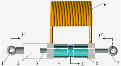
The inertia effect of the fluid inerter is provided by the fluid flowing in the helical long channel. It is similar with the rack-and-pinion inerter or the ball-screw inerter, in that the fluid flowing in the helical channel can be taken as the ‘fluid flywheel’ to enlarge the inertia force. According to different positions of the helical channel, inside or outside the cylinder, there are two types of the fluid inerter. The fluid inerter with the helical channel outside the cylinder is designed in this paper to study its dynamic performance. The prototype of the fluid inerter is shown in Fig. 1.
In Fig. 1, 1 and 7 are the ear hangings that connected to the two sides of the force, 2 is the working room, 3 is the piston rod, 4 is the piston, 5 is the hydraulic cylinder, 6 is the helical channel.
The hydraulic cylinder and the piston rod are the two terminals of the fluid inerter. When the two ear hangings move together by a pair of force , the piston rod and the piston will push the fluid in the left of the hydraulic cylinder into the helical channel. Then the fluid flows through the helical channel into the right hydraulic cylinder in order to compensate the pressure loss. The above is the working principle of the fluid inerter.
Fig. 1Prototype of fluid inerter
3. Dynamic model of fluid inerter
3.1. Definition of the inertance
The fluid in the cylinder and the helical channel is taken as non-compressible. The effective area of the hydraulic cylinder is:
where is the radius of the piston rod, is the inside radius of the hydraulic cylinder.
The section area of the helical channel is:
where is the radius of the helical channel.
The length of the helical channel can be approximated as:
where is the circle number of the helical channel, is the pitch of the helical channel, is the helix radius of the helical channel, is the length from the inlet and outlet to the helical channel.
The mass of the fluid in the helical channel is:
where is the oil density.
If the movement of the piston is , according to the volume conservation principle, the angular displacement meets the relation as:
and hence:
The inertia around the central axis of the fluid in the helical channel is:
According to the law of conservation of the energy:
So, the inertance can be gotten by the following equation:
It can be inferred that the inertance of the fluid is determined by the mass of the fluid in the helical channel, the effective area of the hydraulic cylinder, the section area of the helical channel, the pitch and the helix radius of the helical channel.
3.2. Optimized modeling of fluid inerter
The performance of the fluid inerter may be affected by the friction between the piston and the hydraulic cylinder, the viscous damping force of the fluid and the pressure loss produced by the fluid flow inside the helical channel and the inlet and outlet of the helical channel. In [23], the shear friction between the piston and the cylinder seems to be neglected. Since the effective travel of the fluid inerter is not very large, and the main flow in the helical channel is too much stronger than the secondary flow in the vertical direction. In this study, the secondary flow in the helical channel is not taken into consideration.
Firstly, the fluid flow is assumed laminar, in that case, the Reynolds Number is met:
where is the viscosity of the fluid, is the velocity of the fluid in the helical channel.
According to the Hagen Poiseuille Law, the flow of the fluid in the helical channel and the pressure drop between the two terminals have the relation as:
So the average flow velocity of fluid in the helical channel is:
A fluid flow entering a new channel will experience an energy loss at the inlet and outlet of the hydraulic cylinder. The empirical formula for the resulting pressure drop is given in [24]. The pressure drop across the inlet and outlet is thus estimated to be:
The total force on the piston is:
where is the friction between the piston and the hydraulic cylinder.
According to the volume conservation law:
So, the total force of the inerter can be gained as:
The total force of the fluid inerter involves the inertia force, damping force and the friction. The fluid inerter has a nonlinear dynamic model especially the damping force which has the relation to not only with the velocity but also with the square of the velocity of the piston.
The friction model is:
where is the amplitude of the friction, is the velocity of the piston, is a symbolic function, it is 1 when and –1 when . The direction of friction between the piston and hydraulic cylinder is related to the velocity of the piston and has the constant value. The dynamic model of the fluid inerter can be shown in Fig. 2.
Fig. 2Dynamic model of fluid inerter. q is the displacement of the input, b is the inertance, c is the damping coefficient
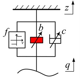
During the optimized modeling of the fluid inerter, the target function is set as the difference between the mean value of force amplitude under the sinuous displacement input of simulation and experiment. It is noted that there are some constraints that both of the inertance and the damping coefficient are related to the structure parameters, which should meet the relationships shown in Eq. (17). We can also see that, in low frequency, the velocity and the acceleration of the piston rod is very small so that the damping force and the inertia force can be ignored. The total force of the inerter can be seen as the amplitude of the friction. In Fig. 2., the inertia force and damping force are all variable because the variety of the oil density and viscosity of the fluid are decided by the temperature. But in this paper, the effects of the variable of the oil density and viscosity are neglected in the study.
4. Nonlinear factors’ effect on the fluid inerter
In this section, the effect of the friction, oil density and viscosity of the fluid will be discussed based on the simulation. The main parameters of the dynamic model of the fluid inerter are shown in Table 1.
Table 1Parameters of the fluid inerter
Name | Value |
Radius of piston rod / m | 0.012 |
Inner radius of the cylinder / m | 0.028 |
Radius of the helical channel / m | 0.005 |
Helix radius of channel / m | 0.1 |
Pitch of helical channel / m | 0.012 |
Circle number of helical channel | 14 |
Oil density / kg·m-3 | 800 |
Length of transition section / m | 0.1 |
Viscosity of fluid / Pa·s | 0.027 |
4.1. Effect of the friction
In order to investigate the effect of the friction on the performance of fluid inerter, the amplitude of the sinusoidal displacement input is set as 20 mm, the oil density is 800 kg·m-3, the viscosity of the fluid is 0.027 Pa·s, the friction is set as 100 N, 500 N, 1000 N and the excitation frequency is set as 0.1 Hz, 1 Hz and 5 Hz. Figs. 3-5 show the effect of the different friction under different frequency.
In Fig. 3, the force of the fluid inerter under 0.1 Hz is approximately a square wave just like the theoretical model of . The amplitude of the total force is very close to the amplitude of because the inertia force and damping force are very small in 0.1 Hz and can be ignored. Fig. 4. shows that the friction also has a large effect on the total force of the fluid, but the effect is smaller than that in 0.1 Hz. In Fig. 5, the friction has a small effect on the total force in 5 Hz because the damping force and inertia force become much larger than the friction with the increase of the input frequency.
From the analysis above, it can be concluded that the friction just has a large effect in low frequency and the effect will become smaller and smaller with the increase of the frequency.
Fig. 3Force under 0.1 Hz input
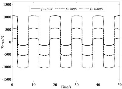
Fig. 4Force under 1 Hz input
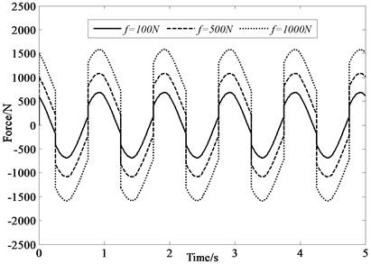
Fig. 5Force under 5 Hz input
4.2. Effect of oil density
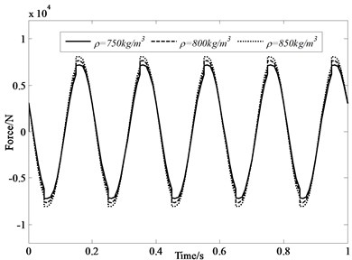
In order to investigate the effect of the oil density on the performance of fluid inerter, the amplitude of the sinusoidal displacement input is set as 20 mm, the viscosity of the fluid is 0.027 Pa·s, the friction is set as 300 N, the oil density is set as 750 kg·m-3, 800 kg·m-3 and 850 kg·m-3 and the excitation frequency is set as 0.1 Hz, 1 Hz and 5 Hz.
Figs. 6-8 show the effect of the different oil density under different frequency. It can be seen that there is not obvious difference in the force of the fluid inerter under 0.1 Hz and 1 Hz. Under 5 Hz, the difference is larger compared with that under 0.1 Hz and 1 Hz, because the change of the inertia force is more apparent in high frequency. The oil density is usually decreased with the increase of the temperature of the fluid. In actual, the variable range of the oil density decided by the temperature is far smaller than the simulation range. So, it can be concluded that the oil density’s effect on dynamic performance of the fluid inerter is very small and can be ignored.
Fig. 6Force under 0.1 Hz input
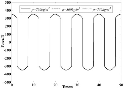
Fig. 7Force under 1 Hz input
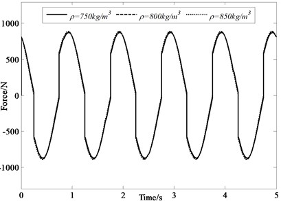
Fig. 8Force under 5 Hz input
4.3. Effect of viscosity
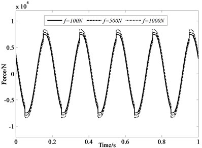
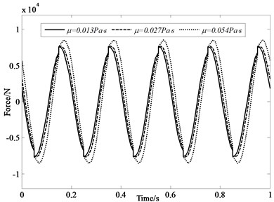
In order to investigate the effect of the viscosity on the performance of fluid inerter, the amplitude of the sinusoidal displacement input is set as 20 mm, the friction is set as 300 N, the oil density is set as 800 kg·m-3. The viscosity is set as 0.013 Pa·s, 0.027 Pa·s and 0.054 Pa·s and the excitation frequency is set as 0.1 Hz, 1 Hz and 5 Hz. Figs. 9-11 show the effect of the different oil density under different frequency.
Fig. 9Force under 0.1 Hz input
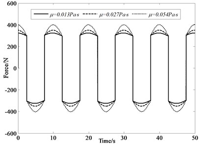
Fig. 10Force under 1 Hz input
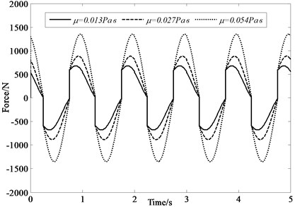
From Figs. 9-11, it can be seen that the total force of fluid inerter is greatly affected by the viscosity of the fluid under different frequencies. In 0.1 Hz and 1 Hz, the damping force has a significant effect. But in 5 Hz, the effect is not apparent compared with that in 0.1 Hz and 1 Hz, which may be because the inertia force is more effective than the damping force in higher frequency. Conclusions can be gained that the viscosity’s effect on dynamic performance of the fluid inerter is relatively large compared with oil density and is not negligible.
Fig. 11Force under 5 Hz input
4.4. Analysis of the three types of force
From the analysis above, it can be seen that there are three types of force in the fluid inerter compromising inertia force, damping force and friction. Fig. 12 shows the amplitude of different types of force with the increase of frequency. The amplitude of the sinusoidal displacement input is set as 10 mm, the friction is 300 N, the viscosity is 0.027 Pa·s and the oil density is 800 kg·m-3.
Fig. 12Amplitude of force under different frequency
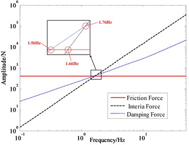
The red line represents for the friction force, it is a constant value. The blue line represents for the damping force and the black line represents for the inertia force. Both of the damping force and the inertia force are becoming larger and larger with the increase of the frequency, because the velocity and the acceleration of the two terminals are all increasing at the same time.
Through the enlarge map, it can be seen that there are three intersections of the three lines. The intersection of the damping force and the friction force is at 1.56 Hz, which means that the damping force is equal to the friction force at 1.56 Hz. Because they have the same direction, there is no special meaning in the intersection.
The intersection of the inertia force and the friction force is at 1.66 Hz, which represents that the inertia force is equal to the friction. The inertia force will be larger than the friction force when the frequency is larger than 1.66 Hz. But the damping force is also larger than the inertia force so that the inertia effect is not obvious.
The intersection of the inertia force and damping force is at 1.76 Hz, which represents that the inertia force is equal to the damping force. The inertia force will be larger than the damping force when the frequency is larger than 1.76 Hz.
It can be inferred that the inertia force and the damping force are relatively small compared with the friction force in low frequency and the damping force is larger than the inertia force. So, the dynamic performance of the fluid inerter is of great damping effect and small inertia effect. With the increase of the frequency, the inertia force is increasing more rapidly than the damping force. When the friction force and the damping force are small enough compared to the inertia force, the dynamic performance of the fluid inerter is of great inertia effect.
To sum up, the friction between the piston and the hydraulic cylinder has a great effect only in low frequency, and the effect becomes smaller with the increase of the frequency because the inertia force and damping force becomes large enough. The damping force is affected mostly by the viscosity and cannot be neglected because the damping force will become larger with the increase of the viscosity. For the inertia force, the variable is relative small changed by the oil density and can be ignored. However, the damping force and the inertia force will become larger with the increase of the frequency, and the speed of inertia force is faster than the damping force. Therefore, the inertia force will become more and more apparent in higher frequency.
5. Experiment
The dynamic performance test of the fluid inerter is carried out in the INSTRON 8800 bench and the force signals can be collected by the sensor at the excited head. The bench test is shown in Fig. 13.
In low frequency, the inertia force and the damping force are very small so that the total force can be seen as friction force. The displacement input is set as a triangle wave and the amplitude is 10 mm.
Fig. 13Bench test
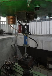
Fig. 14 shows the total force of the fluid inerter under the frequency of 0.1 Hz. It can be inferred that the friction force is a constant value which is 400 N. Then, the total force of the fluid inerter is tested under different frequency to verify the theoretical model.
The amplitude of the sinusoidal displacement input is set as 20 mm under the frequency of 0.1 Hz, 0.3 Hz and 0.5 Hz, 10 mm under the frequency of 3 Hz, 5 Hz and 8 Hz, 5 mm under the frequency of 10 Hz, 12 Hz and 15 Hz.
Fig. 15 shows the comparison and difference of simulation and experiment. It can be seen that in low frequency, the simulation result is very close to the experiment. But in high frequency, the experiment result is smaller than the simulation results. With the increase of frequency, the experiment force is smaller than the simulation force and the difference becomes larger and larger in high frequency. That may be because the temperature of the fluid has been increased for the vibration of the system and the fluid flow is not laminar when is more than 2300.
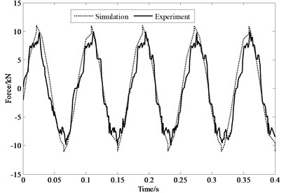
Figs. 16-18 show the time-domain force of the fluid inerter under 0.1 Hz, 0.5 Hz and 12 Hz. It can be concluded that, the experiment results coincide with the simulation quite well, which demonstrates the effectiveness of the dynamic model of the fluid inerter.
Fig. 14Force under 0.1 Hz
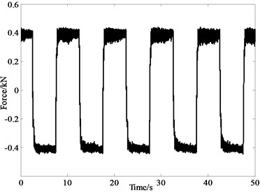
Fig. 15Comparison of simulation and experiment
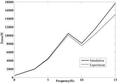
Fig. 16Force under 0.1 Hz
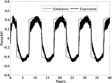
Fig. 17Force under 0.5 Hz
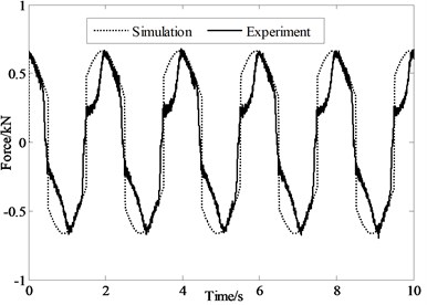
Fig. 18Force under 12 Hz
6. Conclusions
The fluid inerter introduced in this paper seems to be more suitable to the vibration system. In order to investigate the dynamic performance of the fluid inerter, an optimized nonlinear model including the friction, damping force and the inertia force is built. The effect on the force of the nonlinearities compromising friction, oil density and viscosity has been analyzed. The friction has a great effect in low frequency, because the damping force and inertia force is not large enough. The oil density has little effect and can be neglected. The viscosity of the fluid is a very big factor which can affect the damping force mostly. The damping force and the inertia force will become larger and larger with the increase of the frequency and the speed of the inertia force is more rapid than the damping force. At last, a prototype fluid inerter is designed and experimentally tested. Results show that the experiment result is very close to the simulation in the low frequency, but there is much more difference in high frequency, which may be on account of the variable of the temperature and the change of the fluid state.
References
-
Smith M. C. Synthesis of mechanical networks: the inerter. IEEE Transactions on Automatic Control, Vol. 47, Issue 10, 2002, p. 1648-1662.
-
Chen M. Z. Q., Papageorgiou C., Scheibe F., Wang F. C., Smith M. C. The missing mechanical circuit element. IEEE Circuit and System Magazine, Vol. 9, Issue 1, 2009, p. 10-26.
-
Chen M. Z. Q., Smith M. C. Restricted complexity network realizations for passive mechanical control. IEEE Transactions on Automatic Control, Vol. 54, Issue 10, 2009, p. 2290-2301.
-
Jiang J. Z., Smith M. C. Regular positive-real functions and five-element network synthesis for electrical and mechanical networks. IEEE Transactions on Automatic Control, Vol. 56, Issue 6, 2011, p. 1275-1290.
-
Shi H. L., Luo R., Wu P. B., Zeng J., Guo J. Y. Application of DVA theory in vibration reduction of carbody with suspended equipment for high-speed EMU. Science China Technological Sciences, Vol. 57, 2014, p. 1425-1438.
-
Sun H. L., Zhang P. Q., Chen H. B. Application of dynamic vibration absorbers in structural vibration control under multi-frequency harmonic excitations. Applied Acoustics, Vol. 69, 2008, p. 1361-1367.
-
Marian L., Giaralis A. Optimal design of a novel tuned mass-damper-inerter (TMDI) passive vibration control configuration for stochastically support-excited structural systems. Probabilistic Engineering Mechanics, Vol. 38, 2014, p. 156-164.
-
Chen M. Z. Q., Hu Y. L., Huang L. X., Chen G. R. Influence of inerter on natural frequencies of vibration systems. Journal of Sound and Vibration, Vol. 333, Issue 7, 2014, p. 1874-1887.
-
Smith M. C., Wang F. C. Performance benefits in passive vehicle suspensions employing inerters. Vehicle System Dynamics, Vol. 42, Issue 4, 2004, p. 235-257.
-
Papageorgiou C., Smith M. C. Positive real synthesis using matrix inequalities for mechanical networks: application to vehicle suspension. IEEE Transactions on Control System Technology, Vol. 14, Issue 3, 2006, p. 423-434.
-
Kuznetsov A., Mammadov M., Sultan I., Hajilarov R. Optimization of improved suspension system with inerter device of the quarter-car model in vibration analysis. Archive of Applied Mechanics, Vol. 81, Issue 10, 2011, p. 1427-1437.
-
Hu Y. L., Chen M. Z. Q., Shu Z. Passive vehicle suspensions employing inerters with multiple performance requirements. Journal of Sound and Vibration, Vol. 333, Issue 8, 2014, p. 2212-2225.
-
Wang F. C., Liao M. K., Liao B. H., Chan H. A. The performance improvements of train suspension systems with mechanical networks employing inerters. Vehicle System Dynamics, Vol. 47, Issue 7, 2009, p. 805-830.
-
Wang F. C., Liao M. K. The lateral stability of train suspension systems employing inerters. Vehicle System Dynamics, Vol. 48, Issue 5, 2010, p. 619-643.
-
Wang F. C., Hong M. F., Chen C. W. Building suspension with inerters. Proceedings of the Institution of Mechanical Engineers, Part C: Journal of Mechanical Engineering Science, Vol. 224, Issue 8, 2010, p. 1605-1616.
-
Evangelou S., Limebeer D. J. N., Sharp R. S. Steering compensation for high performance motorcycles. Proceedings of the 43rd IEEE Conference on Design and Control, 2004, p. 749-754.
-
Papageorgiou C., Houghton N. E., Smith M. C. Experimental testing and analysis of inerter devices. Journal of Dynamic Systems, Measurement, and Control, Vol. 131, 2009, p. 1-11.
-
Papageorgiou C., Smith M. C. Laboratory experimental testing of inerters. Proceedings of the 44th IEEE Conference on Decision and Control, and the European Control Conference, Seville, Spain, 2005, p. 3351-3356.
-
Wang F. C., Su W. J. Impact of inerter nonlinearities on vehicle suspension control. Vehicle System Dynamics, Vol. 46, Issue 7, 2008, p. 575-595.
-
Wang F. C., Su W. J. Inerter nonlinearities and the impact on suspension control. Proceedings of American Control Conference, Washington, USA, 2008, p. 3245-3250.
-
Wang F. C., Hong M. F., Lin T. C. Designing and testing a hydraulic inerter. Proceedings of the Institution of Mechanical Engineers, Part C: Journal of Mechanical Engineering Science, Vol. 225, Issue 1, 2011, p. 66-72.
-
Glover A. R., Houghton N. E., Long P. J. G., Smith M. C. Force-Controlling Hydraulic Device. International Patent Application No: PCT/GB2010/001491, 2009.
-
Swift S. J., Smith M. C., Glover A. R., Papageorgious C., Gartner B., Houghton N. E. Design and modelling of a fluid inerter. International Journal of Control, Vol. 86, Issue 11, 2013, p. 2035-2051.
-
Massey B. S. Mechanics of Fluids (6th Ed.). Chapman and Hall, London, 1997.
About this article

This work was supported by the National Natural Science Foundation of China (Grant No. 51405202), Scientific Research Innovation Projects of Jiangsu Province (Grant No. KYLX15_1081), the China Postdoctoral Science Foundation (Grant No. 2014M561591), the “Six Talent Peaks” high-level Project of Jiangsu Province (Grant No. 2014-JNHB-023).
Yujie Shen designed the fluid inerter and carried out the experiments, wrote this paper. Long Chen instructed the structure design of the fluid inerter. Yanling Liu collected and analyzed the experiments data. Xiaoliang Zhang assisted to design the fluid inerter. Xiaofeng Yang assisted to carry out the experiments.
