Abstract
Aiming at improving the method of underwater target recognition, this paper proposes a method to estimate the micro-Doppler spectrum parameters of propeller by using inverse Radon transform, so as to obtain the characteristic parameters of propeller. This paper firstly analyzes the basic concepts of micro-Doppler and inverse Radon transform, then defines the algorithm steps of inverse Radon transform for propeller parameter estimation and carries out simulation. The simulation results show that this method can effectively estimate the propeller rotational speed, blade number, blade length and initial spatial position.
Highlights
- Studied the echo modulation characteristics of underwater propeller object.
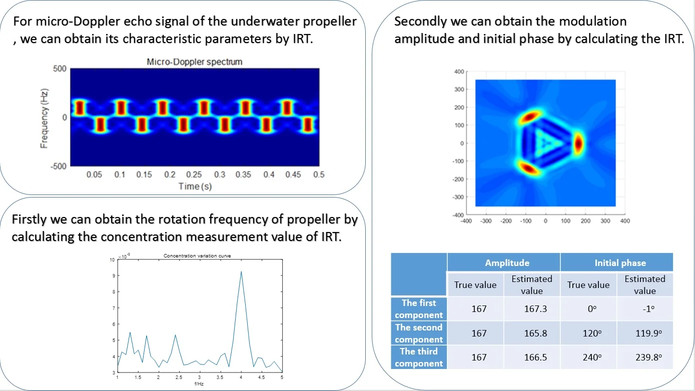
- Expand the application of IRT. The modulation frequency of underwater rotation target echo can be obtained by calculating the concentration measurement value of IRT.
- The modulation amplitude and phase of underwater rotation target echo can be obtained by calculating the IRT for the frequency.
1. Introduction
Due to the difficulty of obtaining target information, the problem of underwater target recognition has not been well solved [1]. At present, the detection and recognition of underwater target mainly depends on the distance, azimuth, speed and highlight echo of target. However, the method is easily affected by the natural environment, marine organisms and artificial interference.
With the successful application of micro-Doppler theory in radar field [2], underwater target detection and recognition has a new approach. Underwater target recognition is usually propelled by propeller which is a typical acoustic scatterer with micro Doppler characteristics. Preliminary exploratory studies on the micro-Doppler characteristics of underwater rotating targets have been carried out by domestic and foreign scholars, and the possibility of its application in the detection and recognition of underwater targets has been confirmed [3, 4].
To estimate the micro-Doppler parameters of rotating objects such as propellers, some adopt the method with variable step size which is out of work when the SNR drops below 5 dB [5]; Some adopt the rotor speed and size estimation method of four rotor UAV based on the combination of instantaneous frequency estimation based on Gabor transform and fast Fourier transform which is also not suitable for low SNR [6]; And based on the scattering point model based on rotor blade some choose SPWV time-frequency transformation method combined with image processing to estimate the speed and size of helicopter rotor, which is subject to the number of scattering points and low SNR [7]. The method based on inverse Radon transform (IRT) can overcome above defeats and better solve the problem of micro-Doppler parameter estimation [8, 9].
This paper applies the micro-Doppler parameter estimation method based on IRT in radar field to the micro-Doppler parameter estimation of underwater propeller.
2. The micro-Doppler characteristics of propeller
Assume that the acoustic detection equipment emits a continuous wave signal with a frequency of [10], i.e.:
Considering the rotating motion of the underwater propeller, it is assumed that the spatial position relationship between the underwater acoustic detection equipment and the propeller is shown in Fig. 1.
Fig. 1Spatial relationship between acoustic detection equipment and propeller
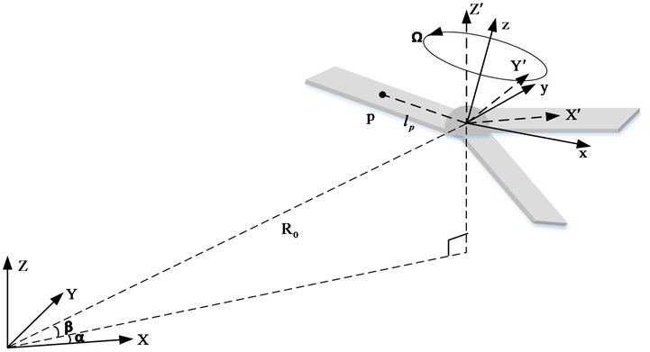
The acoustic detection equipment is used as the origin to establish the spatial fixed coordinate system ; the rotation axis center of the propeller is taken as the origin to establish the target coordinate system ; the origin of the target coordinate system is adopted as the origin to establish the reference coordinate system . The reference coordinate system is parallel to the spatial fixed coordinate system. Assume that the Euler angle from the target coordinate system to the reference coordinate system is , the rotation sequence is , and the propeller rotates around the axis at an angular rate . Assume that the acoustic scattering point on the propeller blade is located in the target coordinate system , and the initial rotation angle at the time is , the rotation angle at the time becomes . According to the geometric relationship in Fig. 1, the distance between the acoustic detection equipment and the scattering point is:
where: is the vector of the acoustic detection equipment pointing to the origin of the reference coordinate system, is the distance between the acoustic detection equipment and the origin of the reference coordinate system; is the translational velocity vector of the propeller relative to the detection equipment; is the vector of the scattering point in the target coordinate system ; is the distance from the acoustic scattering point to the origin of the target coordinate system; is the rotation matrix from the target coordinate system to the reference coordinate system and:
where:
Assume that there is only propeller echo and the effects of reverberation and multipath interference are not considered, the echo signal of rotating propeller received by acoustic detection equipment is:
where, is the number of propeller blades; is the target scattering intensity of each blade; is the initial phase of the blade; is the blade length.
Then the baseband signal of propeller echo is:
Then the echo phase function of the scattering point of the th blade is:
The micro-Doppler frequency of the scattering point of the th blade can be obtained by deriving the phase function:
where is the wavelength of the transmitted signal [11].
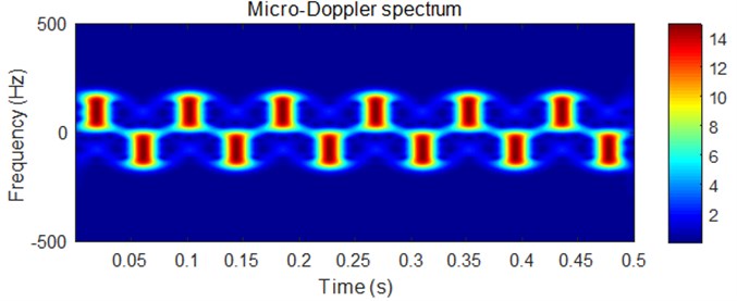
Fig. 2Micro-Doppler characteristic of propeller echo signal
Assume that the propeller has three blades, the acoustic detection equipment emits a single frequency continuous wave signal with a frequency of 100 kHz, the distance between the acoustic detection equipment and the origin of the target coordinate system is 100 m, and 0°, 0°, the Euler angle of the target coordinate system transformed into the reference coordinate system is , the blade length is m, the rotation speed is r/s, the target scattering intensity is , the initial rotation angles of each blade at the time are 0°, 120° and 240°, then the micro-Doppler spectrum of the propeller echo is shown in Fig. 2, in which the darker the color is, the greater the amplitude is.
It can be seen from the figure above that the micro-Doppler spectrum of propeller echo is a cluster of sinusoidal curves, in which the short line alternating at the peak position is the strong echo generated by the mirror reflection of the blade [12].
3. Micro Doppler parameter estimation method based on inverse Radon transform
3.1. Basic concepts of inverse Radon transform
The projection of the 2-D function on the -axis is:
Use coordinate transformation to describe the rotation form of 2-D function in the rotation coordinate system . For the rotation angle , the coordinate transformation is:
If the function is projected onto with a varying rotation angle , which is the Radon transform, that is:
where is the 2-D function in the rotating coordinate system , that is:
Assume a point in xoy coordinate system can be expressed as in uov coordinate system, where , . Then the Radon transformation is:
It can be seen that the points in the plane are transformed into sinusoidal curves in domain by Radon transformation. The amplitude of the sinusoidal curve is , and the phase is [13]-[16]. If Radon transform is given, the 2-D function generating Radon transform is the inverse Radon transform. Therefore, the points in the plane can be transformed into sinusoidal images in the Radon transform domain, which means that the sinusoidal images in the Radon transform domain can be transformed into points in the plane by using the inverse Radon, i.e.:
When all signal energy is concentrated at one point, the parameter estimation is very robust.
3.2. Micro-Doppler parameter estimation based on inverse Radon transform
In order to realize the target recognition, it is usually necessary to obtain the physical and motion parameters of the target. For the propeller, that is, the speed of the propeller, the length of the blade, the number of blades and the initial phase of each blade, these parameters can be obtained by the frequency, amplitude, initial phase of the micro-Doppler spectrum and the number of energy points in IRT domain.
For the rotating propeller, the micro-Doppler spectrum is a cluster of sinusoidal curves, i.e.:
where, superscript indicates the kth spectral line.
By comparing Eq. (12) and (14), it can be seen . So can be used to replace . From the analysis in the previous section, for the time-frequency image shown in Fig. 3, there will be at least one highly concentrated peak in the IRT domain. Its distance to the origin is the modulation parameter , and its angle is . In this way, the modulation parameters and can be estimated accurately in the IRT domain.
The modulation parameters can be estimated by coordinate changes. Assume that the parameters and , change the parameters within a series of possible value, and search for with the maximum concentration in the IRT domain. Because of , the modulation parameters are estimated [17-19].
It can be found that the concentration measurement based on the maximum is more robust and suitable for the maximum detection in the IRT domain. Therefore, the concentration measurement method based on the maximum is also used in this paper.
3.3. Parameter estimation steps
Based on the above analysis, the algorithm of IRT adopted in this paper is summarized as follows:
Step 1: for the signal with unknown modulation parameters, estimate its micro-Doppler frequency range, that is , and set the number of estimated components to 0.
Step 2: if the energy of the signal is not negligible or higher than the expected noise energy, set and repeat the following steps [20].
Step 3: calculate the time-frequency representation of the signal and obtain its two-dimensional time-frequency image.
Step 4: set to equally spaced values between and . For each , calculate and the IRT of the time-frequency image .
Step 5: calculate the concentration measurement value of IRT for each and find the that produces the highest concentration.
Step 6: estimate the kth modulation frequency .
Step 7: calculate the position of the maximum IRT value for and express it as and .
Step 8: estimate the modulation amplitude and phase of the th component:
Step 9: filter out the kth component by demodulating the current signal, i.e.:
Calculate the spectrum of the demodulated signal, and remove the component of zero frequency by setting and several adjacent points to 0. Then calculate and modulate it to eliminate the frequency shift of the residual component caused by demodulation [21]:
Step 10: set and go to step 2.
For underwater propeller target, the obtained parameter is the rotation frequency of the propeller, the obtained parameter is the frequency peak value of the micro-Doppler spectrum. So, the physical size of the propeller can be obtained by and . is the initial phase of the propeller blade which can calculated its initial position of the propeller blade. Thus, more precise target features can be obtained.
4. Simulation
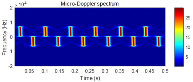
Assume that the emission frequency of the acoustic detection equipment is 10 kHz single frequency continuous wave signal, the detection equipment is 1000 m away from the target, the blade length 0.5 m, rotation speed 4 r/s and the initial rotation angle at the time are 0°, 120° and 240°, and 0°, the micro-Doppler characteristics of the propeller echo signal will be like what is shown in Fig. 3.
Fig. 3Micro-Doppler characteristics of echo signal
The concentration variation curve of micro-Doppler spectrum for frequency estimation is shown in Fig. 4.
Fig. 4Concentration variation curve of micro-Doppler spectrum for frequency estimation
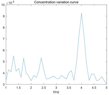
It can be seen from the figure above that the peak appears at 4 Hz, which is the propeller rotation speed. So, the frequency of micro-Doppler spectrum is accurately estimated.
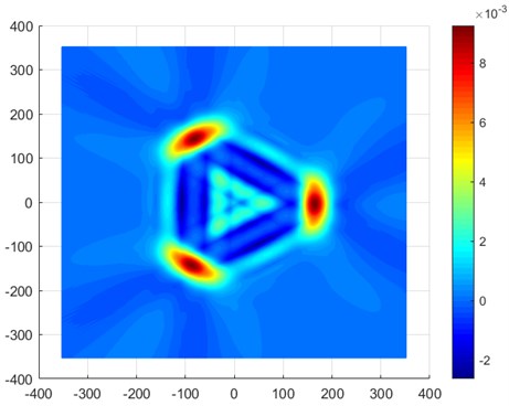
Fig. 5 shows the IRT transformation results of micro-Doppler spectrum. There are three obvious peaks in the figure. Therefore, it can be determined that there are three blades.
Fig. 5Inverse Radon transform of micro-Doppler spectrum
So, the characteristic parameters of micro-Doppler spectrum can be estimated, as shown in Table 1.
Table 1Estimated parameters of micro-Doppler spectrum
Amplitude | Initial phase | |||
True value | Estimated value | True value | Estimated value | |
The first component | 167 | 167.3 | 0° | –1° |
The second component | 167 | 165.8 | 120° | 119.9o |
The third component | 167 | 166.5 | 240° | 239.8o |
From the above analysis, it can be seen that the propeller target has three blades; the rotation speed is about 4 r/s; the propeller blade length is about 0.5 m; and the three blades are symmetrically distributed in space.
5. Conclusions
Aiming at better solving the problem of micro-Doppler parameter estimation of underwater propeller, a parameter estimation method based on IRT is proposed in this paper. Though the simulation analysis in Chapter 4, we can find that the method can estimate the change frequency of the micro-Doppler spectrum by the concentration variation of micro-Doppler spectrum, can estimate the amplitude and initial phase of the micro-Doppler spectrum by its IRT results. By means of relationship between them, we can obtain the propeller rotation speed, blade length, blade number and blade initial spatial position, which is the fine characteristics of underwater target and can be applied to underwater target recognition.
References
-
Y.-S. Cheng, Z.-Z. Li, and J.-X. Qiu, Underwater Acoustic Target Recognition. Beijing: Science Press, 2020.
-
V. C. Chen, “Doppler signatures of radar backscattering from objects with micro-motions,” IET Signal Processing, Vol. 2, No. 3, pp. 291–300, 2008, https://doi.org/10.1049/iet-spr:20070137
-
T. Bo and S. Qiang, “Analysis on suppression of echo signal of target body and translation in micro-DOPPLER signal processing,” in Lecture Notes in Electrical Engineering, Singapore: Springer Singapore, 2020, pp. 205–211, https://doi.org/10.1007/978-981-15-0187-6_23
-
K. Rajat, S. Inderdeep, and S. R. Shobha, “Micro-Doppler signatures of underwater vehicles using acoustic radar,” in Radar Conference, pp. 1222–1227, 2015.
-
S. Xia, L. Xiang, and M. Zhu, “A variable-step high accuracy extraction algorithm for micro-motion target parameters,” Radar Science and Technology, Vol. 17, No. 5, pp. 506–512, 2019.
-
Ma Jiao, Dong Yongwei, Li Yuan, Li Lingxiao, and Yang Jiefang, “Multi-rotor UAV’s micro-Doppler characteristic analysis and feature extraction,” Journal of University of Chinese Academy of Sciences, Vol. 36, No. 2, p. 235, Mar. 2019, https://doi.org/10.7523/j.issn.2095-6134.2019.02.011
-
Chen Guang-Feng, Zhang Lin-Rang, and Liu Gao-Gao, “Parameter estimation of helicopter blade based on micro-doppler analysis,” Computer Engineering, Vol. 38, No. 17, pp. 249–253, 2012.
-
Yan Hong-Hua, Fu Xiong-Jun, and Li Ping, “Detection and measurement to multiple scatters with micro-motion based on inverse Radon transform,” Transactions of Beijing Institute of Technology, Vol. 32, No. 5, pp. 526–530, 2012.
-
Li Kang-Le, Liu Yong-Xiang, and Jiang Wei-Dong, “Reconstruction of target with micro-motions based on inverse Radon transform,” Radar Science and Technology, Vol. 8, No. 1, pp. 74–79, 2010.
-
Chen Xiaolong, Nan Zhao, Zhang Hai, Chen Weishi, and Guan Jian, “Experimental research on radar micro-Doppler of flying bird and rotor UAV,” Chinese Journal of Radio Science, Vol. 36, No. 5, pp. 704–714, 2021, https://doi.org/10.12265/j.cjors.2020192
-
Q. Zhang and Y. Luo, Micro-Doppler Effect of Radar Targets. National Defense Industry Press, 2013.
-
Y.-B. Chen, S.-D. Li, and J. Yang, “Rotor blades echo modeling and mechanism analysis of flashes phenomena,” Acta Physica Sinica, Vol. 65, No. 13, p. 13840, 2016.
-
D. Sun, M. Lu, J. Mei, S. Wang, and Y. Pei, “Generalized Radon transform approach to target motion parameter estimation using a stationary underwater vector hydrophone,” The Journal of the Acoustical Society of America, Vol. 150, No. 2, pp. 952–968, Aug. 2021, https://doi.org/10.1121/10.0005813
-
Z. Fang, H. Zhang, and J. Zhu, “Parameter calibration and imaging analysis of CT system based on Radon inverse transform,” Natural Sciences Journal of Harbin Normal University, Vol. 34, No. 2, pp. 21–25, 2021.
-
Y.-Q. Wang, F. Zhou, and S.-Q. Wang, “Sparse representation of micro – Doppler feature of ballistic target based on inverse Radon transform,” Fire Control and Command Control, Vol. 42, No. 9, pp. 55–59, 2017.
-
T.-L. Zhao, G.-S. Liao, and Z.-W. Yang, “Micro-Doppler extraction based on short-time iterative adaptive approach and inverse Radon transform,” Acta Electronica Sinica, Vol. 44, No. 3, pp. 505–513, 2016.
-
Y. Zhou, X. Wei, and J. Yang, “An estimation method of rotor target micro-motion parameters based on inverse Radon transform,” Journal of Air Force Early Warning Academy, Vol. 33, pp. 391–395, 2019.
-
C. Song, L. Zhou, Y. Wu, and C. Ding, “An estimation method of micro-movement parameters of UAV based on the concentration of time-frequency,” Journal of Electronics and Information Technology, Vol. 42, No. 8, pp. 2029–2036, Aug. 2020, https://doi.org/10.11999/jeit190309
-
X. Chen, J. Guan, W. Chen, L. Zhang, and X. Yu, “Sparse long-time coherent integration-based detection method for radar low-observable manoeuvring target,” IET Radar, Sonar and Navigation, Vol. 14, No. 4, pp. 538–546, Apr. 2020, https://doi.org/10.1049/iet-rsn.2019.0313
-
S. Rahman and D. A. Robertson, “Radar micro-Doppler signatures of drones and birds at K-band and W-band,” Scientific Reports, Vol. 8, No. 1, pp. 1–11, Dec. 2018, https://doi.org/10.1038/s41598-018-35880-9
-
Zhang Pengfei, Li Gang, Huo Chaoying, and Yin Hongcheng, “Classification of drones based on micro-Doppler radar signatures using dual radar sensors,” Journal of Radars, Vol. 7, No. 5, pp. 557–564, Oct. 2018, https://doi.org/10.12000/jr18061
About this article

