Abstract
The mechanical properties of the steel-concrete joint determine the mechanical properties of the whole bridge. The mechanical properties of the steel-concrete joint of Jianhua railway rigid-frame bridge are analyzed by using nonlinear finite element method. The results show that the overall stiffness transition of the joint is smooth, the maximum stress of concrete section and steel box girder section are lower than the design value of the strength, which indicates that the structural stiffness and strength of the steel-concrete joint section meets the requirements. The error range of the finite element analysis results and the measured data is within 6 %, which shows that the finite element method can simulate the actual stress state of the bridge and it could save a lot of time and energy compared to the actual test.
1. Introduction
The steel-concrete hybrid beam bridge replaces the mid-span concrete girder with steel girder. Compared with the full concrete structure, the mid-span steel box girder is installed on-site, which shortens the construction period and has a low self-weight. Compared with the all-steel structure, the steel consumption is less, and it has good rigidity, integrity and stability. The steel has good tensile properties. Changing the concrete section to a steel box girder section can better bear the tensile force, which can increase the span of the main span.
Since there are two different materials for the steel-concrete joint, detailed mechanical performance analysis is required for this section. Many scholars have done related research. Zheng Zhoujun et al. [1] studied the stress state and distribution law of each part of the combined section. Wu Jianmin [2] studied the force transmission mechanism and bearing capacity of the steel-concrete transition section. Liu Y. [3, 4] studied the mechanical properties and force transmission mechanism of the joint section. Cheng X. [5] studied the longitudinal force transmission mechanism of the steel-concrete transition section. Liu Anshuang et al. [6, 7] carried out strength tests and fatigue tests on steel-concrete joint against the background of the Caiyuanba Yangtze River Bridge. He S. et al. [8] tested multiple embedded PBL connectors and obtained the calculation formula of bearing capacity. Zhou Weixiang et al. [9, 10] conducted push-out tests on PBL connectors and analyzed their mechanical properties.
Until now, many researches are conducted based on actual testing with accurate and real results, but it consumes a lot of time and energy. The rapid development of the finite element method provides a more convenient and efficient method. This paper analyzes the steel-concrete joints with nonlinear finite element method, which proves that this joint has good mechanical properties. Meanwhile, it verifies the accuracy of the finite element method by comparing with the measured results.
2. Project background
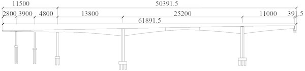
The Jiahua bridge is a steel-concrete hybrid rigid-frame bridge with a main span of 252 m and a total length of 618.915 m. The full bridge consists of steel box girder, concrete box girder and steel-concrete transition section. The main girder of 92 m length is a steel box girder, and the main girder in other positions is full-prestressed concrete structure.
Fig. 1Layout of the bridge elevation (unit: cm)
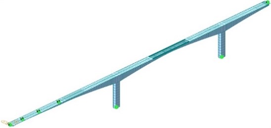
3. Finite element model of the whole bridge
The concrete section of the main girder of the bridge uses C60 concrete, the steel box girder section uses Q345qD and Q420qD steel. Midas civil, a finite element analysis software, is used to model and analyze the whole bridge model, which is divided into 218 units and 221 nodes. The bottom of the piers are consolidated, and only RY direction can rotate at both ends of the bridge. Fig. 2 is the schematic diagram of the finite element model of the whole bridge.
Fig. 2The finite element model of the whole bridge
4. Finite element analysis of steel-concrete joint
4.1. Finite element model
The steel-concrete transition section is composed of 10.2 m long concrete beam section, 1.5 m long concrete cast-in-place section, 2.5 m long concrete site-connection section and 4.5 m long steel box girder section. The total length of the steel-concrete joint is 18.7 m.
The symmetrical half structure is used to equivalent the original structure. The concrete box girder is meshed by C3D4 solid elements, the steel box girder is simulated by S4R shell elements, the prestressed steel bars are simulated by the three-dimensional bar element B31, and the PBL connectors are simulated by SPRING2 linear spring elements. The overall model of the steel-concrete transition section is divided into 1989656 elements, including 1816651 solid elements, 168976 shell elements, 3159 rod elements, and 870 spring elements. The characteristics of the materials used are consistent with the full bridge model. The force transmission of the pressure plate is considered through contact simulation, and the prestress is applied through the cooling method. Fig. 3 is the schematic diagram of the finite element model of the steel-concrete joint.
Fig. 3Finite element model of steel-concrete joint
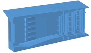
a) Meshing dividing
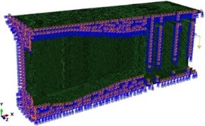
b) Boundary conditions
4.2. Finite element analysis
The load calculated by the finite element model of the whole bridge is applied to the finite element model of the joint, and the vertical displacement distribution of the model is calculated, as shown in Fig. 4. It can be seen from the figure that the maximum vertical displacement of the steel-concrete transition section is –13.929 mm, which appears at the center of the top plate of the end section of the steel box girder.
Fig. 4Vertical displacement cloud map (unit: mm)
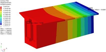
Fig. 5The deflection curve
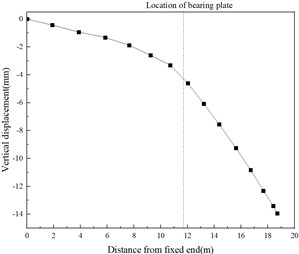
The vertical displacement results of each point on the center line of the top plate are extracted, and the deflection curve of the steel-concrete joint is shown in Fig. 5. The deflection of the steel-concrete joint is nearly smooth, which indicates that the stiffness transition of the joint is smooth. The mixing of two different materials in the steel-concrete joint does not cause sudden change in the stiffness of the overall structure. The joint and the rest of the bridge structure form a whole and work together.
Fig. 6The longitudinal stress distribution of the concrete section (unit: MPa)
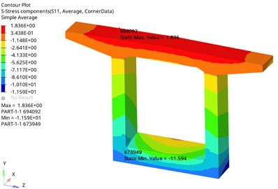
The longitudinal stress distribution of the concrete section is shown in Fig. 6. It can be seen from the figure that under the action of prestress and external load, the concrete box girder presents a state in which the top slab is under tension and the bottom plate is under compression. The maximum tensile stress is 1.836 MPa, which appears near the top slab. At the position of the web, the maximum compressive stress is 11.594 MPa, which appears on the outside of the junction between the bottom plate and the web. The tensile and compressive stresses are less than the design strength of C60 concrete.
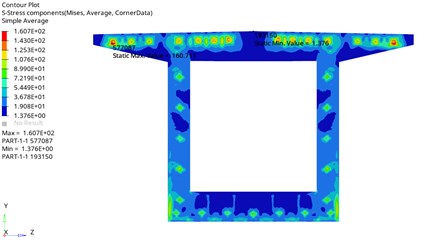
The Mises stress distribution of the bearing plate is shown in Fig. 7. It can be seen from the figure that the maximum Mises stress of the bearing plate is 160.711 MPa, which appears at the anchorage of the prestressed tendons of the top plate. Except for the stress concentration, the Mises stress on the bearing plate is below 107.6 MPa, which is much lower than the yield strength of Q420qD steel.
Fig. 7The Mises stress distribution of the bearing plate (unit: MPa)
4.3. Comparison between finite element analysis results and measured results
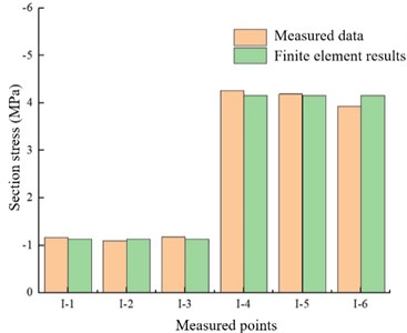
The measured data is obtained by embedding stress sensors on site, and the section I located at the steel-concrete joint is compared with the finite element analysis results.
The comparison between the measured data on site and the finite element results is shown in Fig. 8. it can be seen that the simulated stress at I-1 is 2.5 % different from the measured stress, the simulated stress at I-2 is 2.7 % from the measured stress, and the simulated stress at I-3 is 4.2 % from the measured stress. The simulated stress at position I-4 differs from the measured stress by 2.34 %, the simulated stress at position I-5 differs from the measured stress by 0.71 %, and the simulated stress at position I-6 differs from the measured stress by 5.8 %. The error range of the simulated stress and the measured data at each position of the I section is within 6 %, which shows that the finite element results are reliable. Therefore, for other complex joints or structures, similar finite element analysis methods can be used to obtain mechanical properties close to the actual measured results. Of course, it is necessary to conduct actual measurements for some important structures.
Fig. 8The comparison between the measured data and the finite element results
5. Conclusions
The nonlinear finite element analysis of steel-concrete joint is carried out, and the main conclusions are as follows:
1) Steel-concrete joints have good mechanical properties. In terms of stiffness, the deflection curve of the steel-concrete joint changes smoothly without obvious abrupt changes, and the rigidity transition of the steel-concrete joint is smooth, which means the joint and the rest of the bridge structure form a whole and work together. In terms of strength, the maximum stress of the concrete section and the steel box girder section are both lower than their strength design values, indicating that the structural strength of the steel-concrete joint section meets the requirements.
2) The finite element analysis method can simulate the force situation of steel-concrete joint very well. The error range of the finite element analysis results and the measured data are both within 6 %. For other complex joints or structures, similar methods can also be used, which can help researchers reduce the time and energy consumption caused by actual measurement.
References
-
Zheng Zhoujun and Chen Kaili, “Research on the mechanism of shear nails in the joint section of hybrid girder cable-stayed bridge,” Journal of Wuhan University of Technology, Vol. 32, No. 1, pp. 767–770, 2008.
-
Wu Jianmin, “Model test study of composite girder joint of long-span cable-stayed bridge,” Tongji University, Shanghai, 2009.
-
R. Liu and Y. Liu, “Analysis of auxiliary ribs in steel-concrete joint of hybrid girder,” Journal of Constructional Steel Research, Vol. 112, pp. 363–372, Sep. 2015, https://doi.org/10.1016/j.jcsr.2015.05.015
-
J. He, Y. Liu, and B. Pei, “Experimental study of the steel-concrete connection in hybrid cable-stayed bridges,” Journal of Performance of Constructed Facilities, Vol. 28, No. 3, pp. 559–570, Jun. 2014, https://doi.org/10.1061/(asce)cf.1943-5509.0000444
-
X. Cheng, X. Nie, and J. Fan, “Structural performance and strength prediction of steel-to-concrete box girder deck transition zone of hybrid steel-concrete cable-stayed bridges,” Journal of Bridge Engineering, Vol. 21, No. 11, p. 04016083, Nov. 2016, https://doi.org/10.1061/(asce)be.1943-5592.0000958
-
Liu Anshuang et al., “Design of steel-concrete joints for the main arch of Chongqing Caiyuanba Yangtze River Bridge,” World Bridges, Vol. 4, pp. 27–30, 2006.
-
Liu Anshuang et al., “Structural detail design of Chongqing Caiyuanba Yangtze River Bridge,” Highway, Vol. 4, pp. 65–68, 2007.
-
S. He, Z. Fang, Y. Fang, M. Liu, L. Liu, and A. S. Mosallam, “Experimental study on perfobond strip connector in steel-concrete joints of hybrid bridges,” Journal of Constructional Steel Research, Vol. 118, pp. 169–179, Mar. 2016, https://doi.org/10.1016/j.jcsr.2015.11.009
-
Liu Yuqing, Zhou Weixiang, and Jiang Jinsong, “Experimental research on shear performance of perforated plate connectors,” Bridge Construction, Vol. 43, No. 6, pp. 1–4, 2006.
-
Zhou Weixiang, “Experimental research on steel and concrete connection of continuous composite beam bridge,” Tongji University, Shanghai, 2007.
About this article

This research was supported by the Science and Technology Research Program of Chongqing Municipal Education Commission (Grant No. KJZD-K201905201), Graduate Scientific Research Innovation Foundation of Chongqing under the Grant No. CYB20028, and Chongqing Municipal Natural Science Foundation under the Grant No. cstc2021jcyj-bsh0189.
