Abstract
A steel-concrete hybrid continuous rigid frame bridge was used for the Jiahua bridge. The span layout is 138 m + 252 m + 110 m. The steel box-girder, 90 m in length, was arranged in the middle of the mid-span. During the construction process of this bridge, the adopted method for the large steel box girder section is the whole lifting process, which is not common for this type of bridge. This study investigates the mechanical behavior of the steel-concrete joint through finite element analysis, aiming to understand the stress distributions of the long-span steel box girder in several integral hoisting conditions, which can be a reference to the construction of similar steel box bridges. The results show that the bottom plate stress of the mid-span section has a linear relationship with the lifting acceleration; the top plate stress of the mid-span section has a cubic nonlinear relationship with the lifting acceleration.
Highlights
- This study investigates the mechanical behavior of the steel-concrete joint through finite element analysis
- This study aims to understand the stress distributions of the long-span steel box girder in several integral hoisting conditions
- The results show that the bottom plate stress of the mid-span section has a linear relationship with the lifting acceleration.
1. Introduction
At present, the hybrid girder structure is mainly used in two types of bridges, namely cable-stayed bridges and self-anchored suspension bridges [1], while its application in continuous rigid frame bridges and even continuous girder bridges are relatively rare. To significantly reduce the self-weight of the structure and increase the span capacity of the bridge, a new type of bridge structure is obtained by setting the concrete box girders in the side span and the middle span near the main pier and setting the steel box girders in the middle span of the span [2, 3]. For the construction of this type of bridge, the overall lifting of the larger span and tonnage steel box girder in the middle span becomes an inevitable problem. The quality and safety control during the overall lifting process is directly related to the later construction of the bridge, so it is necessary to analyze and study the mechanical properties of such steel box girders under various normal and extreme working conditions during the lifting process.
For a long time, many researchers focus on the mechanical properties of steel-concrete hybrid bridges [4-6]. Lin et al. [7] conducted a 1:3 reduced version model test analysis of the steel-hybrid transition section, combined with the method of finite element analysis, to study the force transfer mechanism of the steel-hybrid transition section. The test results showed that the stress distribution of the steel-hybrid transition section members was reasonable and the stress level was low. Liu [8] introduced the key technical design points in the design process of the main girder, such as the determination of the anchorage type of the cable-steel box girder, the study of the anchorage durability of the cable-concrete girder, and the selection of the type and location of the steel-composite transition section, using the Erdong Yangtze River Bridge in Hubei Province as the engineering background. He et al. [9] investigated the relationship between parameters such as stress distribution and relative slip in the steel-mixed transition section and the mechanical properties and force transfer mechanism of the combined section by constructing a model. The results showed that the transition section bearing plates and shear connectors can transfer the stress concentration generated during the loading of steel box girder to concrete uniformly by bearing axial force and shear force, respectively.
Previous studies mainly focused on the mechanical performance analysis of the transition section of hybrid structure bridge and the final closure control study of steel box girders, while there were fewer studies on the mechanical performance of lifting of the combined structure of the continuous rigid bridge. Therefore, it is necessary to study the static-dynamic analysis of the bridge mass sections during the lifting process, to ensure the safety of the steel box girder lifting process. In this paper, using ABAQUS finite element software, the stresses at the bottom and top plate of the steel box girder span mid-section under different accelerations are analyzed, and the relationship between stress and acceleration is also analyzed.
2. Background
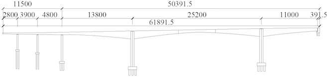
A steel-concrete hybrid continuous rigid frame bridge was used for the Jiahua bridge. The span layout is 138 m + 252 m +110 m. The steel box-girder, 87 m in length, was arranged in the middle of the mid-span, the rest of the main span is made of the concrete structure. A schematic diagram of the bridge elevation is shown in Fig. 1.
Fig. 1Schematic diagram of the bridge elevation (unit: cm)
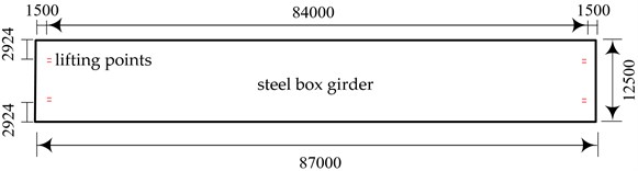
The steel box girder hoisting adopts the method of integral lifting by the bridge deck crane. During the hoisting, two lifting points are set at both ends of the steel box girder, a total of 4 lifting points are located directly above the web and 1.5 m from the end. The position of the lifting point is shown in Fig. 2.
Fig. 2Arrangement of lifting points (unit: mm)
3. Analysis of finite element model of steel box girder
3.1. Steel box girder modeling
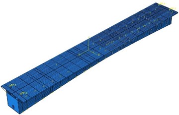
In this study, the finite element software Abaqus is used to analyze the steel box girder hoisting process. The steel box girder bottom plate, top plate, web plate, and other steel box girder main structure steel plates adopt Q420qD, while other steel plates (such as upper beams, transverse partitions, splicing plates, stress anchor plate) adopts Q345qD, steel elastic modulus is 2×10¹² N/m2, Poisson’s ratio is 0.3, mass density is 7850 g/cm3, steel box girder bottom plate and top plate are simulated by solid elements. Considering the analysis of the hoisting process, lateral and longitudinal constraints are imposed on the four hoisting points respectively. The finite element model of the steel box girder is shown in Fig. 3. Ten kinds of accelerations of 0.1 m/s2 to 1 m/s2 in the vertical direction are applied to the four lifting points to simulate the different states of the steel box girder in the acceleration phase.
Fig. 3The finite element model of the steel box girder
3.2. Force analysis under its weight
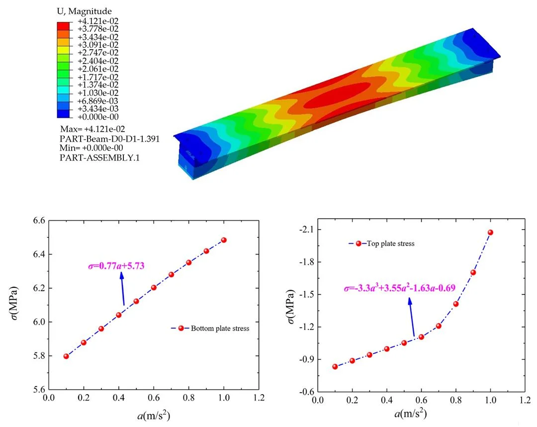
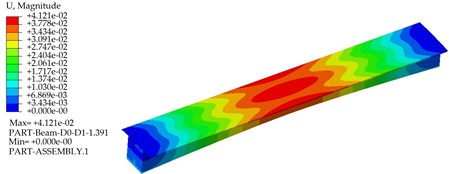
Based on Abaqus finite element analysis software, the stress state of the steel box girder at the lifting moment is simulated by fixing the four lifting points in the direction of restraint, the displacement cloud of the steel box girder is obtained by software analysis as shown in Fig. 4.
It can be observed from the figure that the maximum deformation of the steel box girder is 41.21 mm. At the mid-span position, its deformation is less than 87000 mm/500 = 174 mm, which meets the requirements of the specification in China.
Fig. 4Displacement cloud diagram of steel box girder (unit: m)
4. The effect of acceleration on the stress of bottom and top plate in mid-span section
In this section, the stresses in the steel box girder during the lifting process are studied by Abaqus finite element analysis software, focusing on the principal stresses in the top and bottom plates under ten different accelerations from 0.1 m/s2 to 1 m/s2. The vertical acceleration is applied at the four lifting points to simulate the different states of the steel box girder during the acceleration phase. For convince, only the principal stresses in the top and bottom plates of the span section and the lifting point section are analyzed. The calculated stresses in the bottom and top plates at the mid-span section are shown in Table 1 and Table 2, respectively.
Table 1The stress value of the bottom plate of the lifting acceleration of the mid-span section
Acceleration (m/s2) | 0.1 | 0.2 | 0.3 | 0.4 | 0.5 | 0.6 | 0.7 | 0.8 | 0.9 | 1.0 |
Stress value (MPa) | 5.797 | 5.878 | 5.960 | 6.041 | 6.122 | 6.203 | 6.280 | 6.351 | 6.419 | 6.484 |
Table 2The stress value of the top plate of the lifting acceleration of the mid-span section
Acceleration (m/s2) | 0.1 | 0.2 | 0.3 | 0.4 | 0.5 | 0.6 | 0.7 | 0.8 | 0.9 | 1.0 |
Stress value (MPa) | –0.83 | –0.89 | –0.94 | –1.0 | –1.05 | –1.11 | –1.21 | –1.41 | –1.70 | –2.07 |
According to the bottom and top plate stress results obtained from the analysis of Table 1 and Table 2, the results are plotted in Fig. 5, from which it is obvious that the bottom plate stress of the mid-span section increases linearly with the increase of acceleration, and by fitting the bottom plate stress with the acceleration , the unity linear regression equation is obtained as = 0.77 + 5.73. Thus, it can be inferred that the bottom plate stress of the mid-span section of the steel box girder during the uniform speed lifting process is 5.73 MPa.
Fig. 5The fitting stress-acceleration curve
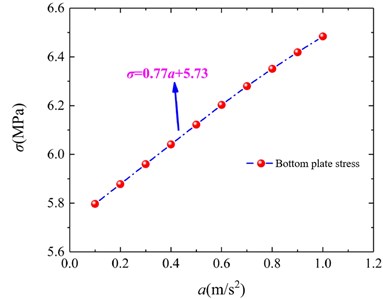
a) Bottom plate stress-acceleration curve
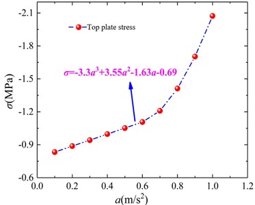
b) Top plate stress-acceleration curve
5. Conclusions
The finite element analysis of the steel box girder of the mid-span is carried out, and the main conclusions are as follows:
1) The steel box girder of the steel-concrete hybrid continuous rigid frame bridge has many difficulties in the lifting process. By analyzing the displacement of the steel box girder during the lifting stage, it provides a partial reference for the linearity of the steel box girder processing in the factory.
2) When the hoisting acceleration increases linearly in steps of 0.1 m/s2, the tensile stress of the mid-span section bottom plate also increases linearly, and the growth rate is relatively slow. However, the compressive stress of the mid-span section top plate exhibits a non-linear growth, and the growth rate is too fast. The top plate compressive stress of the mid-span section is more sensitive to the change of acceleration, so the acceleration should not be too large during the lifting process to prevent the top plate stress of the mid-span section from yielding. At the same time, the acceleration should not change suddenly during the lifting process, otherwise, it will cause a sharp change in the top plate stress. This has an adverse effect on the structure.
References
-
R. Liu and Y. Liu, “Analysis of auxiliary ribs in steel-concrete joint of hybrid girder,” (in Chinese), Journal of Constructional Steel Research, Vol. 112, pp. 363–372, Sep. 2015, https://doi.org/10.1016/j.jcsr.2015.05.015
-
F. Qin, “Study on the mechanical behavior of the continuous hybrid box-girder bridge,” (in Chinese), Tongji University, Shanghai, 2012.
-
Y. Yao, M. Yan, Z. Shi, Y. Wang, and Y. Bao, “Mechanical behavior of an innovative steel-concrete joint for long-span railway hybrid box girder cable-stayed bridges,” Engineering Structures, Vol. 239, p. 112358, Jul. 2021, https://doi.org/10.1016/j.engstruct.2021.112358
-
Q. Pu, S. Yang, Z. Shi, Y. Hong, and Y. Zhou, “Fatigue performance of an innovative steel-concrete joint in long-span railway hybrid box girder cable-stayed bridges,” Journal of Bridge Engineering, Vol. 26, No. 2, p. 04020129, Feb. 2021, https://doi.org/10.1061/(asce)be.1943-5592.0001680
-
Y. Liu, Q. Zhang, W. Meng, Y. Bao, and Y. Bu, “Transverse fatigue behaviour of steel-UHPC composite deck with large-size U-ribs,” Engineering Structures, Vol. 180, pp. 388–399, Feb. 2019, https://doi.org/10.1016/j.engstruct.2018.11.057
-
S. He, A. S. Mosallam, Z. Fang, and L. Liu, “Structural evaluation of steel-concrete joint with UHPC grout in single cable-plane hybrid cable-stayed bridges,” Journal of Bridge Engineering, Vol. 24, No. 4, p. 04019022, Apr. 2019, https://doi.org/10.1061/(asce)be.1943-5592.0001379
-
L. Xiao, H. Ye, X. Wei, and S. Qiang, “Study on mechanical behavior and load transfer mechanism of steel-concrete composite joint of cable-stayed bridge pylon,” (in Chinese), Tumu Gongcheng Xuebao/China Civil Engineering Journal, Vol. 47, No. 3, pp. 88–96, Mar. 2014.
-
R. Liu and Y. Liu, “Analysis of auxiliary ribs in steel-concrete joint of hybrid girder,” Journal of Constructional Steel Research, Vol. 112, pp. 363–372, Sep. 2015, https://doi.org/10.1016/j.jcsr.2015.05.015
-
J. He, Y. Liu, and B. Pei, “Experimental study of the steel-concrete connection in hybrid cable-stayed bridges,” Journal of Performance of Constructed Facilities, Vol. 28, No. 3, pp. 559–570, Jun. 2014, https://doi.org/10.1061/(asce)cf.1943-5509.0000444
About this article

This research was supported by the Science and Technology Research Program of Chongqing Municipal Education Commission (Grant No. KJZD-K201905201), the China Postdoctoral Science Foundation (Grant No. 2021M690838) and Chongqing Municipal Natural Science Foundation under the Grant No. cstc2021jcyj-bsh0189.
