Abstract
To address the rattling noise issue of a Twin-tube hydraulic shock absorber for a electric vehicle, a road test and subjective evaluation were performed. The diagnostic method of the rattling noise source of the shock absorber is studied, and three methods are used to process the test date: the fast Fourier transform can only obtain the main frequency band of the rattling noise; and the short-time Fourier transform can roughly diagnose the frequency band and the occurrence time; using wavelet transform technology combined with displacement signal can accurately lock the source of rattling noise in the rebound stroke. Furthermore, combined with the internal valve configuration of the shock absorber, the rattling noise source is diagnosed in the rebound valve and the compensation valve. The time of rattling noise and the corresponding working stroke of shock absorber can be quickly locked by using the wavelet transform, which is of great significance to solve the problem of shock absorber rattling noise caused by deficiency design of the internal valve architecture of the shock absorber.
1. Introduction
The shock absorber is an important part of the automobile suspension system. New energy vehicles lack the noise masking of the power and transmission system, and the problem of rattling noise of the shock absorber has attracted more and more attention [1]. When driving on an uneven road, the shock absorber’s damping force fluctuates, causing high-frequency vibration of the piston rod [2]. The high-frequency vibration is transmitted to the vehicle through the body sheet metal, producing rattling noise, which causes the driver and passengers to complain. If the shock absorber’s topmount vibration isolation capacity is insufficient, this rattling noise will be exacerbated. There are two types of methods for resolving shock absorber rattling noise: source elimination and path blocking [3]. If the internal valve structure of the shock absorber needs to be optimized, the damping force fluctuations caused by which valve disc of the shock absorber must be locked [4]. Therefore, it is of great significance to find a method that can accurately diagnose the source of the rattling noise to resolve the complaint.
There are few domestic studies on the diagnosis and analysis of the source of the shock absorber rattling noise, and the majority of them focus on the identification of the shock absorber rattling noise. On the basis of a large number of test data and signal characteristic analysis, Shu et al. [5] proposed a method for identifying the time-domain waveform attenuation of rattling noise of hydraulic twin-tube shock absorbers, with an identification success rate of more than 98.5 percent. Huang et al. [6] investigated the rattling noise identification method of shock absorber bench test and proposed a cluster analysis method based on weight coefficient, which can be used as a reference for large batch and different types of shock absorber rattling noise identification and identification accuracy improvement. The previous studies can only identify the shock absorber’s rattling noise signal and cannot diagnosed the source of the shock absorber's rattling noise.
In this paper, the road test and subjective evaluation of the two shock absorbers with and without rattling noise are carried out, and then, the advantages and disadvantages of three signal processing methods of fast Fourier transform, short-time Fourier transform and wavelet analysis for the diagnosis of rattling noise sources of shock absorbers are compared, finally, a method based on wavelet transform technology combined with the displacement signal of the shock absorber is proposed for accurately diagnosing the rattling noise source of the shock absorber. This method is an important reference for resolving the issue of the rattling noise of the shock absorber.
2. Testing and evaluation of vehicle's shock absorber rattling noise on road
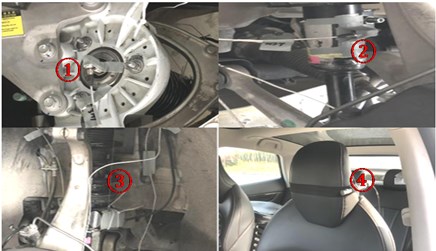
When a domestic electric vehicle is driving at a low speed on rough concrete roads, the front shock absorber produces ratting noise. Select BOB (Best of Best) and WOW (Worst of Worst) from the same batch of shock absorbers for road tests. The designed road test conditions are as follows: driving on a rough cement road at the proving ground at a constant speed of 20 km/h, to collect the vibration signal of piston rod top, displacement signal of the spring and noise inside the car, the sensors attachment locations is shown in Fig. 1 (Accelerometer (1) is located at the top of the piston rod; Accelerometer (2) is located on the wall; (3) is the displacement sensor; (4) is the microphone).
The LMS is used in this test which is a multifunctional data acquisition and analysis system, along with high-fidelity sound playback headphones, to ensure that the noise signal playback accurately reflects people's subjective feelings. Professional vehicle BSR noise evaluation personnel will score the shock absorber, and the scoring mechanism is carried out in accordance with the 10-point system BSR noise performance evaluation standard. BOB pieces scored 7 points on the 10-point system rattling noise evaluation standard, while WOW pieces scored 5 points.
Fig. 1Sensors layout
3. Research on identification method of rattling noise source of shock absorber
3.1. Fast Fourier transform
The fast Fourier transform decomposes the signal into a sine function using trigonometric functions as the basis of the function space, converting the time domain signal to a frequency domain signal. The following is the conversion procedure:
The continuous signal must be discretized in application before it can be processed by the computer. As a result, to obtain discrete samples , the continuous signal must be sampled in the time domain, and its fast Fourier transform can be obtained:
The discrete-time Fourier transform is represented by the formula above. The frequency domain value obtained after the transformation is still continuous, and the frequency domain must be sampled indefinitely to obtain:
The Eq. (4) is the discrete Fourier transform. The time domain signal converted into a frequency domain signal after discrete Fourier transformation. However, for non-stationary signals such as BSR noise, using Fourier transform will lose time-domain information and cannot obtain non-stationary characteristics.
Fourier transform is used to process the collected shock absorber signal, because in this case, the -direction vibration of the top of the piston rod is the main contribution direction of the rattling noise of the shock absorber, so only the -direction data is used to illustrate, the / direction data will not be compared for the time being, and the spectrum diagram of the top of the shock absorber piston rod with and without rattling noise is obtained as follows.
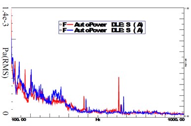
The vibration spectrum of the piston rod, as shown in the figure above, can only see the difference between the vibration spectrum of the shock absorber piston rod with and without rattling noise: The vibration magnitude of the WOW parts is significantly greater than that of the non-BOB parts in the -direction 100-400 Hz frequency band, and the peak frequency is 250 Hz, but the time when the abnormal vibration occurs and the specific working stroke of the corresponding shock absorber cannot be determined. The noise in the driver’s ear is masked by other BSR noises and road noise, the difference between the spectrograms of BOB pieces and WOW pieces is not prominent in the corresponding frequency bands.
Fig. 2Z direction of the top of the shock absorber piston rod (blue is WOW, red is BOB)
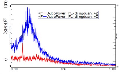
Fig. 3Noise at the driver’s ear (blue is WOW, red is BOB)
3.2. Short-time Fourier transform
It is difficult to analyze the characteristics of non-stationary signals using only the time domain signal or amplitude spectrum, so time-frequency analysis short-time Fourier transform is required. The method of adding time domain information by short-time Fourier transform is to set a window function, it is assumed that the signal in the window function to be a stationary signal, and perform Fourier transform on the signal segment in the window function. The short-time Fourier transform is defined as:
where is the input signal and is the window function, which is reversed in time and has an offset of samples. is a two-dimensional function of time and frequency , which connects the time domain and frequency domain of the signal, and we can perform time-frequency analysis on the signal accordingly.
The short-time Fourier transform is used to analyze the vibration signal at the top of the piston rod of the shock absorber. Since the accuracy of the time and frequency domain results of the short-time Fourier transform is affected by the length of the window function, the window function type in this paper is the Hanning window. The window function lengths are selected as 0.5S and 2S respectively for comprehensive comparison, and the time-frequency diagrams of BOB and WOW parts are obtained as shown in the following figures.
Fig. 4Time-frequency diagram in the Z direction of the top of the piston rod of the BOB piece (0.5S)
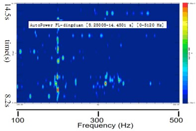
Fig. 5Time-frequency diagram in the Z direction of the top of the piston rod of the BOB piece (2S)
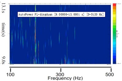
Fig. 6Time-frequency diagram in Z direction at the top of the piston rod of the WOW piece (0.5S)
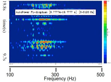
Fig. 7Time-frequency diagram in Z direction of the top of the piston rod of the WOW piece (2S)
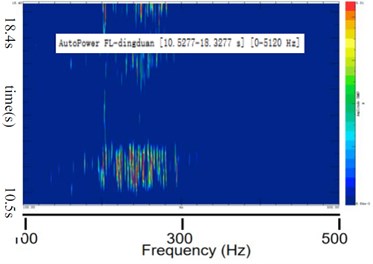
Comparison of WOW and BOB components in the time-frequency domain diagram analyzed by short-time Fourier transformation: As shown in Figs. 6 and 7, when a narrow window function is chosen, the time resolution of the time-frequency diagram is higher and the frequency resolution is lower and vice versa, but the time resolution is low, making it difficult to choose the window function that takes both the time resolution and the frequency resolution of the analysis results into account. Comparing Fig. 4 and Fig. 6, it can be seen that the peak frequency of the BOB part cannot be obtained. The vibration with higher energy occurs at 12.14-12.66 s, 12.92-13.26 s, 16.69-16.89 s, 18.91-19.23 s, the time interval is 0.52 s, 0.34 s, 0.2 s, 0.32 s; Comparing Fig. 5 and Fig. 7, it can be seen that the peak frequency of the WOW part is 260 Hz in -direction, the time corresponding to the peak frequency is between 11.06 and 12.75 s, and the time interval is 1.69 s. Through the above comparison, it is found that the time resolution of the analysis results using a narrower window function is higher than that of using a wider window function, however, under this test condition, the shock absorber works for a cycle time is about 0.1 s, or even less, if the time resolution is enhanced further to meet this operating condition, the frequency resolution will be decreased, making it difficult to apply the short-time Fourier transform to precisely analyze the peak frequency and time of anomalous piston rod vibration at the same time.
3.3. Wavelet transform
The characteristic of wavelet transform is that it can perform multi-resolution analysis at the same time, and it has the ability to characterize the local characteristics of the signal in both time domain and frequency. There are two variables in wavelet transform: and , is the reciprocal of the frequency, which controls the contraction of the wavelet function, and is the time factor, which controls the translation of the wavelet function. For a finite signal of arbitrary energy, its continuous wavelet transform is defined as:
where is the mother wavelet or basic wavelet. Therefore, unlike the basis function of the Fourier transform, which is an infinitely long sine wave, the basis function of the wavelet transform is a finite-length wavelet that has been attenuated, and the wavelet basis function is localized in both the time domain and the frequency domain. Wavelet analysis decomposes the signal into the superposition of a series of wavelet functions. These wavelet functions can be used to approximate the sharply changing parts of the non-stationary signal, and can also approximate the discrete discontinuous signal with local characteristics, so as to reflect the original signal more truly change on a time scale. Since the wavelet transform can achieve an automatic harmony between frequency and time, it can realize the time-frequency multi-resolution function of the signal.
In this paper, the wavelet analysis module of the LMS software is used to analyze the shock absorber signal. The default wavelet basis function is Morlet wavelet. The wavelet transform is used to analyze the vibration signal of the shock absorber piston rod, and the result is shown in the following figures.
Fig. 8Time-frequency diagram of the top Z-direction of the piston rod of the BOB piece
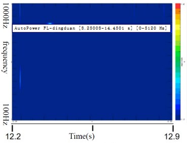
Fig. 9Time-frequency diagram of the Z direction at the top of the piston rod of the WOW piece
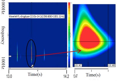
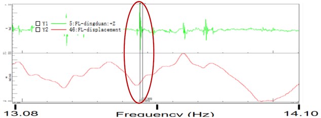
The above figure shows that the vibration energy of WOW parts is much higher than that of BOB parts in the frequency band of 100-400 Hz, and the peak frequency is in the range of 220 Hz-350 Hz. This conclusion is basically consistent with the spectrogram obtained by Fourier analysis. Enlarging the time domain interval, it can be seen that the abnormal vibration of the WOW piston rod in the direction is between 13.47-13.48S. The data of 13.47-13.48S is found in the time domain signal of the WOW component in the direction. Combined with the displacement curve of the shock absorber, get Fig. 10.
It can be seen from the Fig. 10 that the abnormal vibration in the direction of the WOW component occurs during the rebound stroke of the shock absorber. The valves related to the rebound stroke are the rebound valve and the compensation valve. Combined with the force vs disp diagram of the shock absorber and the physical structure of the internal valves of the WOW component, you can adjust the relevant disk in a targeted manner, but it is beyond the scope of this paper. In this case, wavelet analysis is used to precisely lock the shock absorber's rattling noise source to the shock absorber's rebound stroke and to the specific valve. Therefore, wavelet analysis is very effective in finding the rattling noise source of the shock absorber.
Fig. 10Z-direction acceleration-displacement curve of shock absorber piston rod
4. Conclusions
The road test of the shock absorber BOB and WOW parts and subjective evaluation was carried out, and the three methods of Fourier transform, short-time Fourier transform and wavelet analysis were used to diagnose the rattling noise source of the shock absorber respectively. The following conclusions are drawn:
1) Fourier transform can quickly and accurately analyze the spectral characteristic information of the shock absorber piston rod acceleration, but the time information corresponding to the frequency information cannot be obtained.
2) The short-time Fourier transform can roughly analyze the time-frequency domain characteristics of the shock absorber piston rod acceleration signal, but there is a problem in that the analysis accuracy in the frequency domain and the time domain cannot be achieved concurrently. The main peak frequency and corresponding time of the shock absorber rattling noise cannot be precisely locked.
3) The wavelet transform can precisely lock the peak frequency and occurrence time of the abnormal vibration of the shock absorber piston rod. Combined with the shock absorber displacement signal, the rattling noise source can be locked in the rebound valve in piston side and compensation valve in base side.
4) Through the research on the identification method of the shock absorber rattling noise source, it is finally concluded that the wavelet transform combined with the shock absorber displacement signal can quickly and accurately lock the shock absorber rattling noise source to the specific valve configuration. This method has strong operability, is fast and effective, and can play an important role in solving the rattling noise problem of the shock absorber.
References
-
Y. G. Zhu, M. Y. Zhou, and B. Feng, “Rapid identification method of suspension rattling noise based on transfer path analysis,” Journal of Henan Institute of Technology, Vol. 26, No. 6, pp. 8–11, 2018.
-
A. Kruse, M. Eickhoff, and A. Tischer, “Analysis of dynamic behavior of twin-tube vehicle shock absorbers,” SAE International Journal of Passenger Cars – Mechanical Systems, Vol. 2, No. 1, pp. 447–453, Apr. 2009, https://doi.org/10.4271/2009-01-0223
-
M. T. Yao, L. Gu, and J. F. Guan, “Analysis of abnormal noise test of twin-tube shock absorber,” Chinese Journal of Engineering Design, Vol. 17, No. 3, pp. 229–235, 2010.
-
M. T. Yao, J. F. Guan, L. Gu, and Z. Y. Cheng, “Study on abnormal noise of vehicular twin-tube shock absorber,” Machinery Design and Manufacture, No. 2, pp. 114–116, 2011, https://doi.org/10.19356/j.cnki.1001-3997.2011.02.046
-
H. Y. Shu, L. Y. Wang, and Y. W. Cen, “Identification method of abnormal noise of vehicle hydraulic shock absorber,” Journal of Chongqing University, Vol. 28, No. 4, pp. 10–13, 2005.
-
H. B. Huang, R. X. Li, W. P. Ding, M. L. Yang, and H. L. Zhu, “Rig test for identifying abnormal noise of suspension shock absorber,” Journal of Vibration and Shock, Vol. 34, No. 2, pp. 191–196, 2015, https://doi.org/10.13465/j.cnki.jvs.2015.02.034
About this article

