Abstract
As it is difficult to extract the combined faults from rolling bearings of aero-engine in strong noise, a fault diagnosis method based on wavelet transform (WT), principal component analysis (PCA) and self-correlation noise reduction is proposed to solve this problem. The proposed method is then compared with the target matrix composed of maximum component of kurtosis, the largest and the second largest kurtosis value. The result of comparative analysis reveals that the 2D target matrix proposed in this paper works better to extract the characteristic frequency of combined faults of rolling bearings in terms of accuracy and effectiveness.
Highlights
- Wavelet transform (WT), principal component analysis (PCA) and self-correlation noise reduction is proposed to extract the combined faults from rolling bearings of aero-engine in strong noise.
- The proposed method is compared with the target matrix composed of maximum component of kurtosis, the largest and the second largest kurtosis value.
- The two-dimensional matrix selection method selected in this study is completely novel in the field of fault diagnosis.
1. Introduction
Early fault diagnosis of rolling bearings, which serve as an important supporting part of rotary machine, has always been considered as one of the points of research [1]. An early injury on rolling bearings will cause impact force which triggers the high frequency natural vibration of bearing system. Vibration signal is mainly made up by the components of harmonic, fault pulse which is associated with rotate speed and strong noise.
Conclusions from the study of engineering practice show that early faults of bearings mostly exist as combined faults [2] and cannot be diagnosed precisely by traditional methods. In recent years, further studies have found that vibration signal can be self-adapted and decomposed into several modes according to their intrinsic properties. To a certain extent, self-adaptive decomposition method has already become a powerful tool to analyze the signal of rolling bearings, for example, the blade disc diagnosis method [3] contributed by foreign scholars based on ensemble empirical mode decomposition (EEMD) and WT. To explore the correlation of multisource of rolling bearings and similar sensor signal, scholars introduced PCA method [4] to reduce the dimension of multi-dimensional signals. Kurtosis, as an important index to measure instantaneous impact properties of signal [5], has been widely applied to the study of fault diagnosis of rolling bearings. For the studies above, this paper takes the combination of traditional WT and modern PCA methods to determine the fault type of rolling bearings in combined faults.
2. Theoretical basis
2.1. Wavelet transform theory
Signals can be resolved into low-frequency portions (approximate) and high-frequency portions (detailed) by WT, one of common signal processing methods. represents the number of layers of WT and the number is 4 in this paper:
Given finite energy function is , elastic factor, shift factor, and continuous wavelet basis function can be represented as:
Discrete wavelet is to discretize parameters and , namely, , , . Discretized wavelet function is:
2.2. PCA theory
PCA is a statistic dimensionality reduction analysis. It works by retaining the principal components of larger variances while neglecting other components, so as to drastically cut down the dimensionality of signal at the cost of less information.
Supposing that contains samples and each sample includes features, covariance matrix of is:
In which, is the mean value of sample space; assuming characteristic value of is , ,…, , eigenvector is ; making , sample space is reconstructed as:
Sample space is transformed into characteristic sample space by Eq. (5); the in represents the -th main component in sample . Accumulated contribution rate is defined as:
When , the composed by previous eigenvectors is treated as low-dimension projection space, namely the completion of dimensionality reduction.
2.3. Characteristic frequency of rolling bearings
As the fault type of bearings is one-to-one relative to characteristic frequency, a fault type is usually determined by characteristic frequency. Calculation formula of characteristic frequency of rolling bearings is shown as Eq. (7):
where otation frequency – , inner ring fault frequency – , outer ring fault frequency – , rolling element fault frequency – , retainer fault frequency – and variable is rotate speed; the number of rolling elements; the angle of stress direction and perpendicular line of inner and outer ring; and the diameter and pitch diameter of rolling bearings.
2.4. Diagnosis scheme
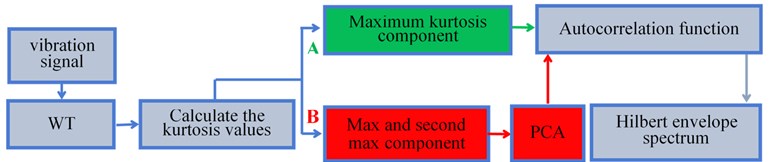
In this paper, a signal analysis method combining WT and PCA is proposed to identify the combined faults of rolling bearings. The flow consists of 5 steps shown in Fig. 1:
(1) Acceleration and vibration signal of rolling bearings is decomposed into 4 layers by sym4 wavelet;
(2) Figure out the kurtosis of high-frequency signal D1 – D4;
(3) Choose the signals relative to the largest and second largest kurtosis and form a 2D target matrix;
(4) Reduce the dimensionality of 2D matrix with PCA to make a new 1D matrix;
(5) Reduce the noise of 1D matrix with self-correlation function and extract characteristic frequency of combined faults through Hilbert demodulation spectrum.
For comparative analysis, the signal components of the largest and second largest kurtosis are chosen to form a 2D target matrix (red block diagram, scheme B) and compare with the signal component of the largest kurtosis (green block diagram, scheme B) to highlight the advantages of proposed WT-PCA method.
Fig. 1Flow chart of diagnostic methods
3. Research on the experimental signal
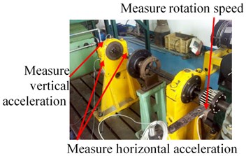
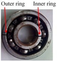
All the data in this paper sources from an aero-engine rotor-rolling bearing fault tester (shown in Fig. 2(a)), which is comprised by adjustable motor, rotating shaft, rotor disc, gear case, ball bearing, bearing block and integrated electronic control system. Geometrical parameters of rolling bearing include: diameter 9.6 mm, pitch diameter 36 mm, number of rolling elements 7 and contact angle 0°. Injury of bearing is made by spark cutting and the depth is 0.2 mm. Fig. 2(b) is the combined fault of inner and outer rings and 2(c) the fault of outer ring and rolling element.
Fig. 2a) Aero-engine rotor-rolling bearing experimental rig, b)-c) compound faults of rolling bearing
a)
b)

c)
3.1. Compound fault diagnosis of outer ring and inner ring-scheme A
Firstly, randomly chose the acceleration signal as an example for analysis, which was picked up by vertical sensors during combined fault of outer and inner ring, and rotate speed of rolling bearing was 1538 r/min. According to Eq. (7), we can have the characteristic frequencies of rolling bearings shown in Table 1.
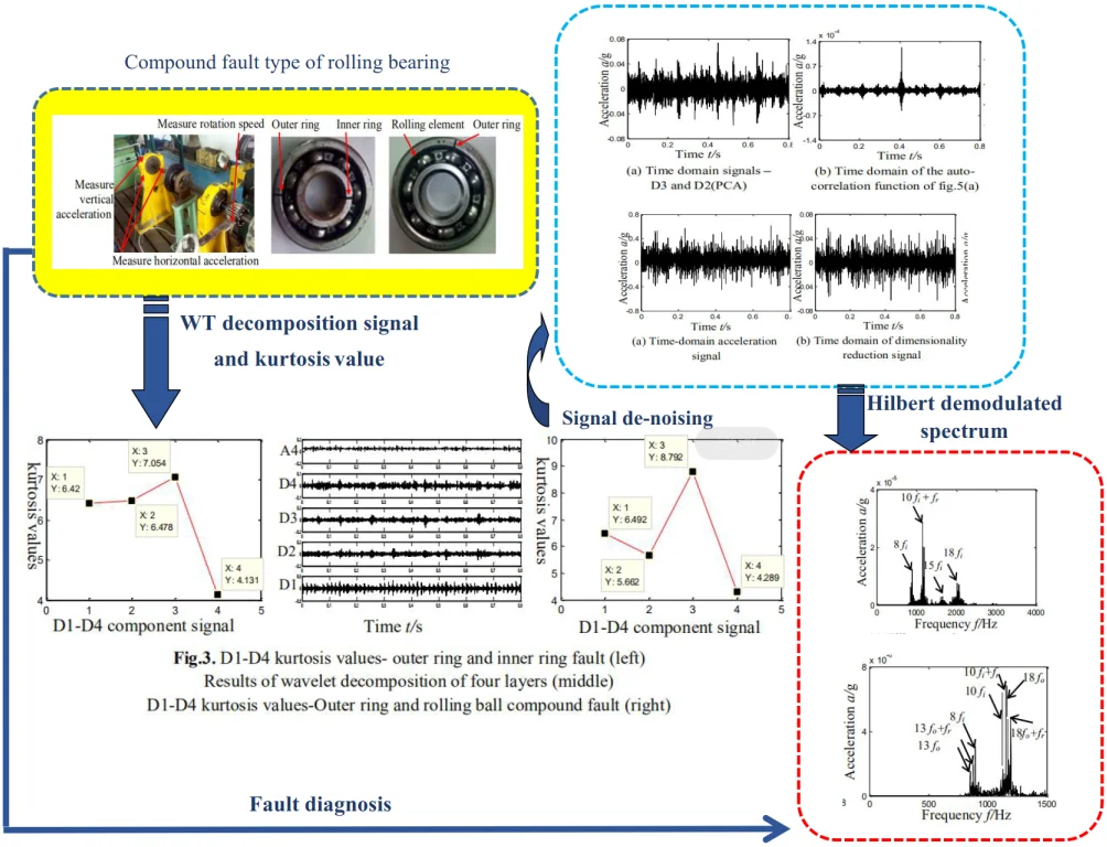
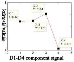
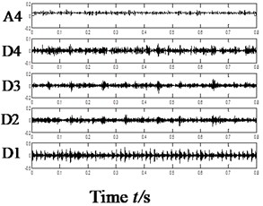
Vibration signal was decomposed by sym4 wavelet. After calculation, we could have the kurtosis D1-D4: 6.42, 6.478, 7.054 and 4.131. Details are shown in Fig. 3(a). Fig. 3(b) the low-frequency and high-frequency time domain of Fig. 4(b) after wavelet transform.
Fig. 3a) D1-D4 kurtosis values- outer ring and inner ring fault, b) results of wavelet decomposition of four layers, c) D1-D4 kurtosis values-Outer ring and rolling ball compound fault
a)
b)
c)
Table 1Fault characteristic frequency-rotational speed 1538r/min- vertical
Characteristic frequency | (Hz) | (Hz) | (Hz) | (Hz) | (Hz) |
Outer ring and inner ring compound fault | 25.6 | 9.4 | 113.6 | 65.8 | 44.7 |
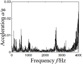
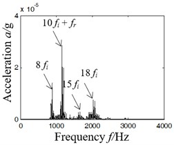
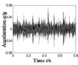
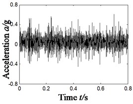
It can be found from the kurtosis of each component shown in Fig. 4 that the kurtosis corresponds to D3, D2, D1 and D4 component in descending order; characteristics were extracted by scheme A, namely, to obtain self-correlation function of D3 component and then extract the characteristic frequency of rolling bearings with Hilbert spectrum envelope based on the self-correlation function. As shown in Fig. 4, 4(a) is the time domain of original vibration signal, 4(b) Hilbert spectrum envelope of 4(a); 4(c) the Hilbert spectrum envelope of self-correlation function of component D3.
Fig. 4Results of compound fault diagnosis of outer ring and inner ring-scheme A
a) Time-domain acceleration signal
b) Hilbert envelope spectrum of Fig. 4(a)
c) Hilbert envelope spectrum
It can be concluded from the analysis of Fig. 4(b) and (d) that:
(1) In Fig. 4(b), Hilbert spectrum envelope of rolling bearing contains too much noise signal to extract characteristic frequencies as effective fault information is covered by strong noise background.
(2) In Fig. 5(d), according to scheme A in Fig. 1 based on the principle of maximum kurtosis, the characteristic frequency of inner ring fault can be found (multiple characteristic frequency of inner ring or the sum of frequency doubling and rotating frequency: 8 (896 Hz), 10 (1154 Hz), 15 (1685 Hz) and 18 (2027 Hz)), but it is unable to extract the characteristic frequency of axonometric outer ring or its multiple frequency component.
3.2. Compound fault diagnosis of outer ring and inner ring-scheme B
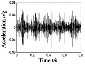
The paper combines wavelet transform and PCA algorithm (scheme B, as shown in Fig. 1). Firstly, make wavelet decomposition of vibration signal (4 layers); secondly, choose the signal components of the largest and second largest kurtosis after wavelet transform (namely, D3 and D2), and use them to form a 2D target matrix; thirdly, reduce the dimensionality of 2D matrix with PCA; fourthly, strive for self-correlation function of 1D matrix and extract characteristics of combined faults with Hilbert spectrum envelope. The result is shown in Fig. 5, in which Fig. 5(a) shows the time domain of dimensionality reduction of 2D target matrix; 5(b) time domain waveform of denoised self-correlation function; 5(c) Hilbert demodulation spectrum.
The following conclusions can be obtained by analyzing Fig. 5:
(1) After analyzing Fig. 5(a), the time domain diagram after dimensionality reduction, it can be observed that the signal comprises of distinct periodic impulse signal, which indicates that the layering and dimensionality reduction method proposed is effective for combined fault diagnosis.
(2) By analyzing Fig. 5(c), we can find characteristic frequency of inner ring and its frequency doubling, 8 (896 Hz), 10 (1154 Hz) and 10 (1128 Hz). Meanwhile, characteristic frequency of outer ring and related frequencies can also be extracted, 13 (854 Hz), 13 (880 Hz), 18 (1170 Hz) and 18 (1196 Hz).
By scheme B, the WT-PCA algorithm proposed by this paper can precisely extract the characteristic frequency of combined fault of inner and outer rings or its frequency doubling, and the performance is obviously superior to scheme A.
Fig. 5Results of compound fault diagnosis of outer ring and inner ring- scheme B
a) Time domain signals D3 and D2(PCA)
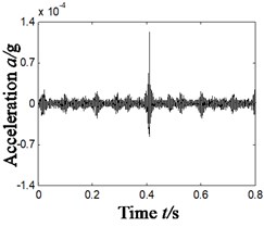
b) Time domain of the auto-correlation function of Fig. 5(a)
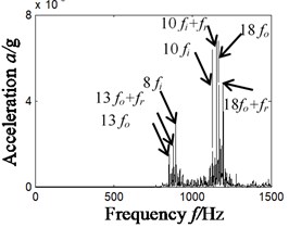
c) Hilbert envelope spectrum of Fig. 5(b)
4. Different types of compound faults
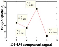
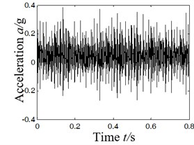
To validate the efficiency of WT-PCA algorithm, we have studied the characteristic extraction of other combined faults. Due to the limit of length, we randomly chose the combined faults of inner and outer rings. Rotate speed of tester is 2007 r/min. According to Eq. (7), namely geometric parameters of bearings, characteristic frequencies of rolling bearings could be obtained by calculation, as shown in Table 2. Kurtosis was calculated and sorted in descending order according to WT-PCA algorithm and the result is shown as follow: D3 (8.792), D1 (6.492), D2 (5.662) and D1 (4.289). For that, component D3 was chosen and the result is shown in Fig. 6, in which 6(a) is the time domain of original vibration signal; 6(b-c) corresponds, dimensionality reduction time domain diagram and Hilbert demodulation spectrum of each component. kurtosis D1-D4 are shown in Fig. 3(c) (5.662, 6.492, 8.792 and 4.289).
Table 2Fault characteristic frequency – different types of compound faults – vertical
Characteristic frequency | (r/min) | (Hz) | (Hz) | (Hz) | (Hz) | (Hz) |
Outer ring and rolling ball compound fault | 2007 | 33.5 | 12.3 | 148.3 | 85.8 | 58 |
After analyzing Fig. 6, we can have the frequency doubling of 3 characteristic frequencies of outer ring, namely 10 (858 Hz), 14 (1192 Hz), 19 (1619 Hz) and frequency doubling of 2 characteristic frequencies of rolling element, namely 16 (912 Hz) and 20 (1138 Hz). That means WT-PCA algorithm can make characteristic extraction of different combined faults of rolling bearings.
Fig. 6Results of compound fault diagnosis of different types of compound faults
a) Time-domain acceleration signal
b) Time domain of dimensionality reduction signal
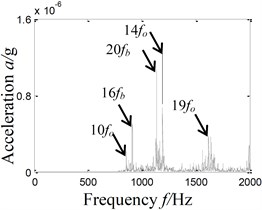
c) Hilbert envelope spectrum
5. Conclusions
The paper combines wavelet transform and PCA algorithm to study the characteristic extraction of combined faults of rolling bearings. It can be concluded that the 2D target matrix building method proposed in this paper is clearly better than other ways and enables the characteristic extraction of different combined faults.
References
-
Pankaj Gupta, Pradhan M. K. Fault detection analysis in rolling element bearing: A review. Materials Today: Proceedings, Vol. 4, Issue 2, 2017, p. 2085-2094.
-
Wang Guobiao, He Zhengjia, et al. Basic research on machinery fault diagnosis – what is the prescription. Journal of Mechanical Engineering, Vol. 49, Issue 1, 2013, p. 63-72.
-
Bouhali, Tadjine, Bendjama, et al. Fault diagnosis of bladed disc using wavelet transform and ensemble empirical mode decomposition. Australian Journal of Mechanical Engineering, Vol. 18, 2020, p. S165-S175.
-
Wang Heng, Ni Guangxian, Chen Jinhai, Qu Jiangming Research on rolling bearing state health monitoring and life prediction based on PCA and Internet of things with multi-sensor. Measurement, Vol. 157, 2020, p. 107657.
-
Chen Juntang, Liao Shiyong, et al. Application of kurtosis analysis on fault feature extraction of engine noise signal. Movable Power Station and Vehicle, Vol. 1, 2011, p. 15-18.
About this article

This work was supported by National Natural Science Foundation of China (Grant No. 51605309), Natural Science Foundation of Liaoning Province (Grant No. 2019-ZD-0219), Aeronautical Science Foundation of China (Grant No. 201933054002) and Provincial Education Department of Liaoning Province (Grant No. JYT19042).
