Abstract
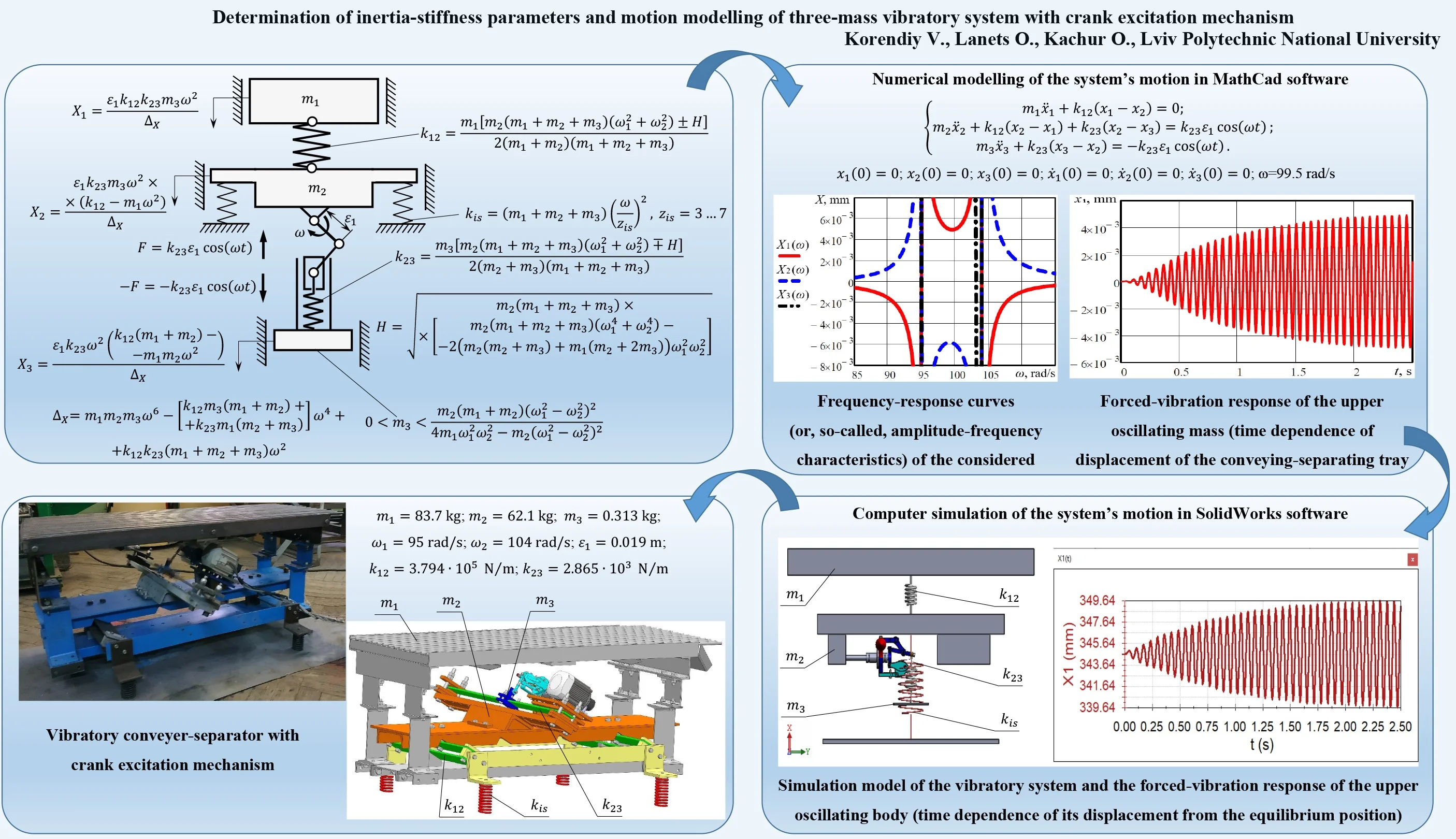
Vibratory technological equipment is widely used in various industries. The vast majority of existing vibratory machines are equipped by single- or double-mass oscillatory systems and inertial or electromagnetic vibration exciters. The novelty of the present study consists in development and investigation of the three-mass oscillatory system with crank excitation mechanism. Such a system can be effectively implemented in various designs of vibratory equipment, e.g., conveyers, separators, feeders, shakers, batchers, sieves, etc. Based on the mathematical model derived in the form of differential equations of the system’s motion, there are deduced the analytical expressions for determining its inertia-stiffness parameters ensuring the energy-efficient resonance operation mode. Using the solid model of the vibratory conveyer-separator designed in SolidWorks software, there is determined the input data for calculating the parameters of the oscillatory system. Based on the results of calculations, the numerical modelling of the system’s motion is carried out in MathCad software. In order to verify the correctness of the theoretical investigations, the simulation of the system’s motion is carried out in SolidWorks Motion software. The comparative analysis of the results of numerical modelling and computer simulation is performed, and the prospects of their implementation are considered.
Highlights
- The three-mass oscillatory system of the vibratory conveyer-separator with crank excitation mechanism is considered and the differential equations describing its motion are derived.
- The analytical expressions for determining the oscillatory system's inertia-stiffness parameters ensuring the energy-efficient resonance operation mode are deduced.
- The solid model of the conveyer-separator is designed and its experimental prototype is implemented in practice. The numerical modelling and computer simulation of the system’s motion are carried out.
- The obtained results can be used while analyzing the conveying speed and the conveying regime (detached (lifted-off) or non-detached) for different types of products (bulky, loose, piecewise etc.).
1. Introduction
The problems of reducing the energy consumption of various technological equipment are currently of significant interest among the scientists and designers. One of the ways of improving the energy efficiency of vibratory machines consists in implementation of three-mass oscillatory systems ensuring the possibilities of operation in so-called “multi-frequency” and “inter-resonance” modes [1-3]. Herewith, the vibrations can be excited by electromagnetic vibrators [1], air-operated vibrators [2], inertial drives [3-6], eccentric-type and crank mechanisms [7-10]. Each type of vibration exciter has its specific advantages and drawbacks, as well as the areas of implementation. The problems of parametric synthesis and dynamic behavior analysis of various oscillatory systems with electromagnetic and inertial vibrators are thoroughly investigated in numerous publications, e.g. [1, 3-6], whereas the air-operated vibrators are not widely used in industrial vibratory equipment because of their design complexity and low efficiency [2].
The crank excitation mechanisms are effectively used for actuating single- and double-mass oscillatory systems of vibratory machines [7-10]. However, the problems of exciting the oscillations of three-mass systems with the help of crank mechanisms are currently of significant interest. The novelty of the present paper consists in developing the technique of determining the inertia-stiffness parameters of the three-mass vibratory system excited by the crank mechanism, as well as modelling and simulation of its motion under near-resonance conditions.
2. Mathematical model and technique of determining the inertia-stiffness parameters of the three-mass vibratory system with crank excitation mechanism
The discrete three-mass vibratory system to be analyzed is presented in Fig. 1. The upper mass and the intermediate mass are connected by the spring . The intermediate mass is supported on the unmovable (stationary) base by two springs considered as vibration isolators. The excitation mechanism consists of the crank 1 hinged to the intermediated mass , and the connecting rod 2 simultaneously hinged to the crank 1 and to the slider 3. The lower mass is connected to the slider 3 of the crank mechanism by the spring .
Let us consider the case when the masses , , oscillate translationally relative to one another due to the uniform rotation of the crank 1 described by the constant angular speed (circular frequency) . The motion of the system can be completely described by the coordinates , and , which define the displacements of the masses from the corresponding equilibrium positions at any time .
Fig. 1Three-mass vibratory system: 1 – crank; 2 – connecting rod; 3 – slider (piston)
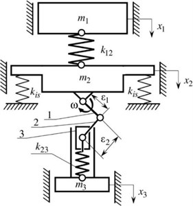
The differential equations of motion of the considered three-degree-of-freedom system can be written in the following form:
where , are the lengths of the crank and of the connecting rod, respectively.
Let us assume that ; this allows us to consider the periodic (harmonic) excitation of the vibratory system. In addition, let us neglect the stiffness of vibration isolators , because its value is considerably smaller than the values of and . In such a case, the system of differential Eq. (1) can be rewritten as follows:
In the case when the system is subjected to the harmonic force , we assume the steady-state solutions to be as follows:
where , , are the amlitude values of displacements of the corresponding oscillating masses that depend on and on the system’s parameters.
Substitution of Eq. (3) into Eq. (2) leads to:
System Eq. (4) represents three algebraic equations in the unknowns , , . The determinant of the coefficients of , , is equal to:
Equalizing the determinant in Eq. (5) to zero, let us derive the frequency (characteristic) equation, whose positive roots are the natural frequencies of the system’s oscillations:
Setting the values of the natural frequencies, and substituting them into Eq. (6), let us derive the analytical expressions for determining the stiffness coefficients and :
where:
Therefore, the input parameters for calculating the inertia-stiffness parameters of the three-mass vibratory system are following: the values of two natural frequencies , , and two masses , . The value of the mass can be estimated taking into account the following assumptions: the radicand in Eq. (8) and the numerators in Eq. (7) must take positive values:
To plot the frequency-response curves (or, so-called, amplitude-frequency characteristics) of the three-mass vibratory system, let us solve Eq. (4) for the unknowns , , :
3. Results of numerical modelling and computer simulation
3.1. Design peculiarities of the vibratory machine
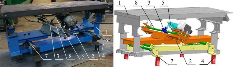
The vibratory conveyer-separator was designed in SolidWorks software and implemented as an experimental prototype (see Fig. 2). It consists of the upper conveying-separating tray 1, intermediate frame 2 supported on the unmovable (stationary) base 6 by vibration isolators 4, and the crank excitation mechanism 5 installed between the intermediate frame 2 and the lower frame (disturbing body) 3. The movable members of the machine (upper tray 1, intermediate frame 2, disturbing body 3) are connected to one another by means of flat springs 7 and 8.
In order to carry out further investigations, it is necessary to prescribe the input parameters using the machine’s solid model and experimental prototype: the mass of the tray ; the mass of the intermediate frame 62.1 kg; the first and the second natural frequencies , ; the lengths of the crank and the connecting rod , . Substituting the input data into Eqs. (7-9), we can estimate the value of the lower mass and calculate the values of the stiffness coefficients , : 0.894 kg; let us adopt ; 3.794∙105 N/m, 2.865∙103 N/m for the first case (see Eq. (7)), or for the second case (see Eq. (7)) 3.28∙105 N/m, 3.314∙103 N/m. In further investigations, let us accept the first case for the calculated values of , .
Fig. 2Vibratory conveyer-separator with crank excitation mechanism: 1 – upper conveying-separating tray; 2 – intermediate frame; 3 – lower frame (disturbing body); 4 – vibration isolators; 5 – crank excitation mechanism; 6 – unmovable (stationary) base; 7, 8 – flat springs
3.2. Numerical modelling of the system’s motion in MathCad software
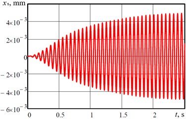
Using Eq. (11), let us plot the frequency-response curves (or, so-called, amplitude-frequency characteristics) of the considered three-mass vibratory system with the help of MathCad software (see Fig. 3). Based on the obtained results, it can be concluded that the resonance effects take place at the frequencies 95 rad/s, 104 rad/s, which correspond to the ones prescribed by the input parameters. Numerical solution of the differential Eq. (2) has been obtained with the help of the Runge-Kutta method using MathCad software taking into account the following initial conditions: ; . As an example, the plot of forced-vibration response of the upper oscillating mass (time dependence of the mass’s displacement from its equilibrium position) is presented in Fig. 4. The vibratory system excited at the forced frequency 99.5 rad/s runs into the steady-state operation mode in 2-3 s after the starting. The maximal displacement of the upper oscillating mass from its equilibrium position, i.e., the amplitude of vibration of the conveying-separating tray, is equal to 5 mm.
Fig. 3Frequency-response curves (or, so-called, amplitude-frequency characteristics) of the considered three-mass vibratory system
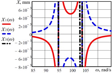
Fig. 4Forced-vibration response of the upper oscillating mass (time dependence of displacement of the conveying-separating tray from its equilibrium position)
3.3. Computer simulation of the system’s motion in SolidWorks software
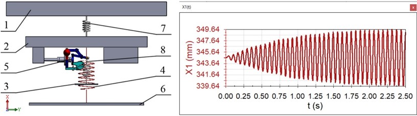
In order to verify the correctness of the results obtained by theoretical investigations and numerical modelling, let us carry out computer simulation of the vibratory system’s motion in SolidWorks Motion software. The corresponding solid model is presented in Fig. 5. It consists of the upper oscillating body 1 (), which is connected by the spring 7 ( 3.794∙105 N/m) with the intermediate oscillating body 2 ( 62.1 kg). The body 2 is supported by the spring 4 (vibration isolator) on the unmovable (stationary) base 6. The crank excitation mechanism 5 is attached to the body 2, and the hinge of its pusher is connected with the spring 8 ( 2.865∙103 N/m) joined to the lower oscillating body 3 ( 0.313 kg). All the other input simulation parameters correspond to the ones prescribed for numerical modelling: forced frequency (angular velocity of the crank rotation) 99.5 rad/s; the lengths of the crank and the connecting rod 0.019 m, 0.078 m. The results of computer simulation are presented as the plot of forced-vibration response of the upper oscillating body (time dependence of the body’s displacement from its equilibrium position, Fig. 5), and are in satisfactory agreement with the results of numerical modelling (Fig. 4).
Fig. 5Simulation model of the vibratory system and the forced-vibration response of the upper oscillating body (time dependence of its displacement from the equilibrium position): 1, 2, 3 – upper, intermediate, and lower oscillating body, respectively; 4 – vibration isolator; 5 – crank excitation mechanism; 6 – unmovable (stationary) base; 7, 8 – springs
4. Conclusions
Based on the carried out investigations, the following conclusions can be drawn:
1) The three-mass oscillatory systems with crank excitation mechanisms are of significant interest among the researchers and designers of vibratory equipment because of their design simplicity, reduced energy consumption, improved possibilities of frequency and amplitude regulation in accordance with the technological requirements etc.
2) The simplified diagram of the three-mass vibratory system has been considered; the differential equations describing the motion of the oscillating masses have been derived; the analytical expressions allowing determination of the inertia-stiffness parameters of the system have been deduced; the frequency-response dependencies have been proposed.
3) Prescribing the input parameters obtained on the basis of solid modelling of the vibratory conveyer-separator in SolidWorks software and implementing it as an experimental prototype, the numerical and computer simulation of the system’s motion has been carried out; the results of theoretical investigations (numerical modelling) have been compared with the results of computer simulation, and the conclusion about their satisfactory agreement has been drawn.
Prescribing the masses 83.7 kg, 62.1 kg, and the natural frequencies 95 rad/s, 104 rad/s, there have been determined the values of the lower mass , and the stiffness coefficients 3.794∙105 N/m, 2.865∙103 N/m. The oscillations of the three-mass vibratory system of the conveyer-separator have been excited by the crank mechanism characterized by the lengths of the crank and the connecting rod 0.019 m, 0.078 m. The numerical modelling and computer simulation showed that at the forced frequency 99.5 rad/s the amplitude of vibration of the upper tray reaches 5 mm.
The results of numerical modelling and computer simulation can be used in further investigations on the subject of the present paper while analyzing all the other kinematic parameters of the masses’ oscillations, in particular, the velocity and acceleration of the tray, which characterize the conveying speed and the conveying regime (detached (lifted-off) or non-detached) for different types of products (bulky, loose, piecewise etc.).
References
-
Gursky V., Kuzio I., Korendiy V. Optimal synthesis and implementation of resonant vibratory systems. Universal Journal of Mechanical Engineering, Vol. 6, Issue 2, 2018, p. 38-46.
-
Kuzo I. V., Lanets O. V., Gurskyi V. M. Synthesis of low-frequency resonance vibratory machines with an aeroinertia drive. Naukovyi Visnyk Natsionalnoho Hirnychoho Universytetu, Vol. 2, 2013, p. 60-67, (in Ukrainian).
-
Yatsun V., Filimonikhin G., Haleeva A., Krivoblotsky L., Machok Y., Mezitis M., Podoprygora N., Sadovyi M., Strautmanis G. Searching for the two-frequency motion modes of a three-mass vibratory machine with a vibration exciter in the form of a passive auto-balancer. Eastern-European Journal of Enterprise Technologies, Vol. 4, Issues 7-106, 2020, p. 103-111.
-
Yaroshevich N., Puts V., Yaroshevich T., Herasymchuk O. Slow oscillations in systems with inertial vibration exciters. Vibroengineering Procedia, Vol. 32, 2020, p. 20-25.
-
Kim A., Doudkin M., Ermilov A., Kustarev G., Sakimov M., Mlynczak M. Analysis of vibroexciters working process of the improved efficiency for ice breaking, construction and road machines. Journal of Vibroengineering, Vol. 22, Issue 3, 2020, p. 465-485.
-
Lanets O. S., Dmytriv V. T., Borovets V. M., Derevenko I. A., Horodetskyy I. M. Analytical model of the two-mass above resonance system of the eccentric-pendulum type vibration table. International Journal of Applied Mechanics and Engineering, Vol. 25, Issue 4, 2020, p. 116-129.
-
Alşverişçi G. F. The nonlinear behavior of vibrational conveyers with single-mass crank-and-rod exciters. Mathematical Problems in Engineering, Vol. 2012, 2012, p. 534189.
-
Mikheyev V. V. New type of vibration generator with vibratory force oriented in preferred direction. Journal of Vibrational Engineering and Technologies, Vol. 6, Issue 2, 2018, p. 149-154.
-
Igumnov A. L., Metrikin S. V., Nikiforova V. I. The dynamics of eccentric vibration mechanism (Part 1). Journal of Vibroengineering, Vol. 19, Issue 7, 2017, p. 4854-4865.
-
Igumnov A. L., Metrikin S. V., Nikiforova V. I., Fevral’skikh L. N. The dynamics of eccentric vibration mechanism (Part 2). Advanced Structured Materials, Vol. 137, 2021, p. 173-190.
Cited by
About this article

