Abstract
The paper considers the motion conditions of a semidefinite vibratory system placed upon a rough horizontal surface. Such systems are sometimes called unrestrained or degenerate ones, and are usually used in various vibration-driven robots and capsules. Unlike the numerous existent investigations dedicated to a similar subject, the novelty of the present paper consists in the implementation of a crank mechanism for exciting oscillations of a double-mass vibro-impact system setting into planar locomotion a robot’s movable body. A general design diagram of the improved semidefinite vibro-impact system is proposed, and the corresponding mechanical diagram is considered. The differential equations describing the system sliding (planar locomotion) along a rough horizontal surface are derived. A thorough analysis of the main inertia-stiffness, design, and excitation parameters influencing the system motion conditions is carried out. Performing the numerical modeling in MathCad software, the dynamic behavior of the robot’s movable body is studied under the specified system’s parameters and operational conditions.
Highlights
- A general design diagram of the improved semidefinite vibro-impact system is proposed, and the corresponding mechanical diagram is considered.
- The differential equations describing the system sliding (planar locomotion) along a rough horizontal surface are derived.
- A thorough analysis of the main inertia-stiffness, design, and excitation parameters influencing the system motion conditions is carried out.
- The dynamic behavior of the robot’s movable body is studied under different system’s parameters and operational conditions.
1. Introduction
It is well-known that the motion of a semidefinite vibratory system is composed of translation and vibration. In such a case, one of the system’s natural frequencies is equal to zero; this means that the system doesn’t oscillate, and translationally moves as a single rigid body without any relative movements of the masses forming this system [1]. That’s why such systems are usually used in various vibration-driven robots and capsules.
The vibration-driven system consisting of a movable rigid body and two internal masses set into oscillatory motion by orthogonally directed periodical forces is studied in [2]. The similar system driven by two orthogonally oscillating internal masses and sliding along a rough horizontal plane is investigated in [3]. In [4], there are considered two types of vibro-impact capsule systems with different types of constraints. The paper [5] is dedicated to the analysis of a stick-slip motion of a 2-DOF vibration-driven system.
In [6], the authors studied the dynamic behavior of a semidefinite vibratory system with a rotating internal mass. The improved design diagram of a vibration-driven system (vibration manipulator) is proposed in [7]. In [8], there is analyzed the dynamic behavior of a vibro-impact locomotion system subjected to the action different friction levels. The paper [9] presents a thorough comparative analysis of two vibration-driven locomotion systems: a common vibratory system and a vibro-impact one.
The novelty of the present paper consists in the implementation of a crank mechanism for exciting oscillations of a double-mass vibro-impact system setting into planar locomotion a robot’s movable body. Some aspects of this topic regarding the sliding motion of the double-mass vibratory system were presented in the paper [10]. The possibilities of implementation of the optimized vibro-impact systems operating under the resonance conditions were considered in [11]. The improved design of a crank mechanism used for exciting oscillations of vibratory equipment was presented in [12]. The present paper is aimed at combining the controllable crank excitation mechanism with a double-mass vibro-impact system in order to provide the effective conditions of the robot motion.
2. Design diagram of semidefinite vibratory system
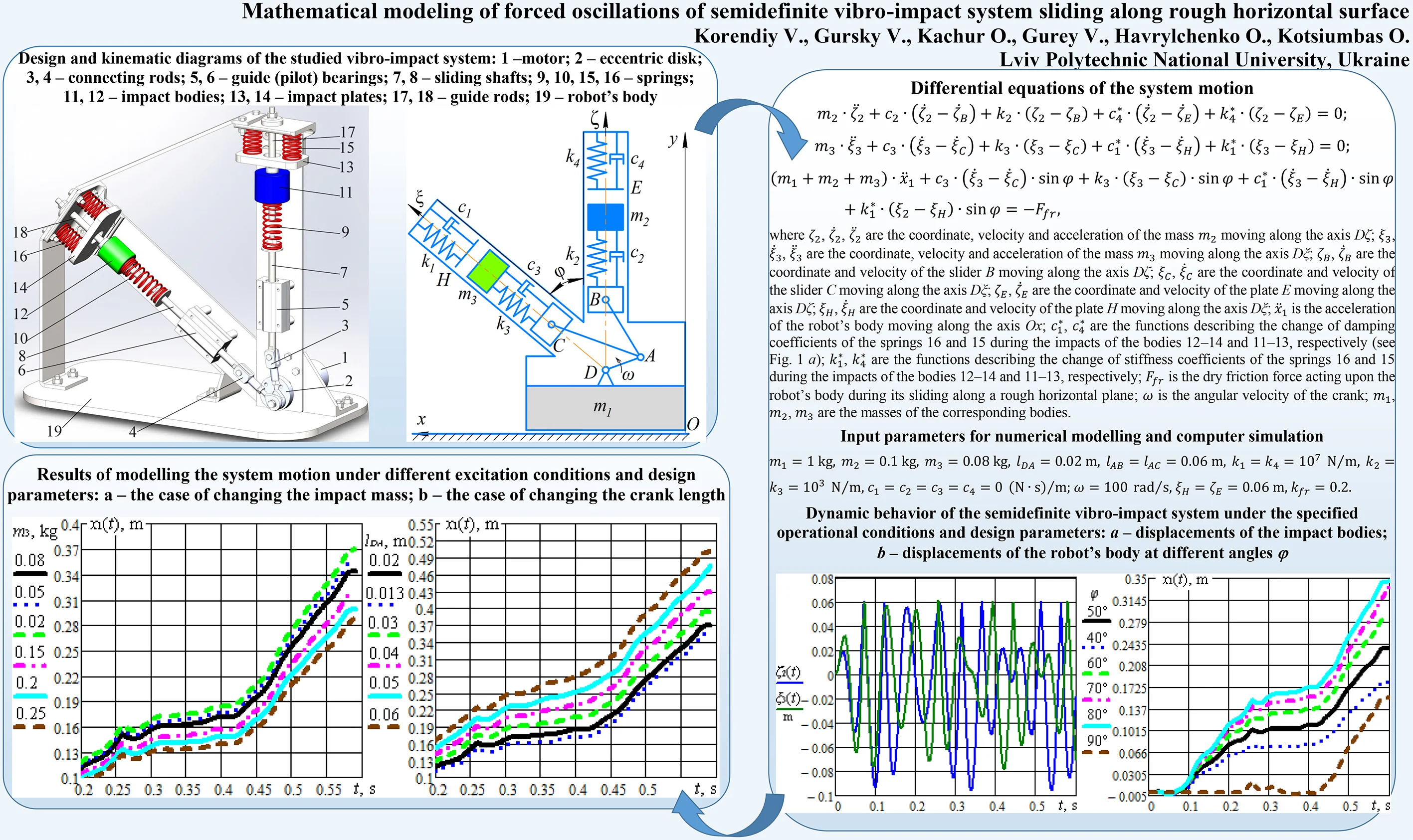
The proposed design diagram of a semidefinite vibro-impact system is presented in Fig. 1(a). The electric motor 1 with changeable rotor speed sets into motion the eccentric disk 2. The latter is hingedly joined with the connecting rods 3 and 4. The sliding shafts 7 and 8 are hinged to the rods 3 and 4, respectively, and translationally move in the guide (pilot) bearings 5 and 6. The springs 9 and 10 are connected to the free ends of the sliding shafts 7 and 8, and, at the same time, to the impact bodies 11 and 12 sliding along the guide rods 17 and 18. The impact plates 13 and 14 are connected to the robot’s body 19 with the help of the springs 15 and 16.
The main idea of the proposed mobile vibratory system consists in setting the robot’s body into the translational motion by implementing the vibro-impact operation modes. The steady-state rotation of the disk 2 causes the straight-line oscillations of the shafts 7 and 8. The corresponding shafts influence the springs 9 and 10 exciting the oscillations of the bodies 11 and 12. The latter ones can impact the plates 13 and 14 under specific operational conditions. The kinetic energy being released during the impact of the body 11 and the plate 13 causes the reduction of the vertical force exerted by the robot’s body upon the supporting surface. Similarly, the kinetic energy being released during the impact of the body 12 and the plate 14 causes both the reduction of the vertical force exerted by the robot’s body upon the supporting surface, and the sliding of the robot’s body along the surface. The mentioned impacts are shifted in time (displaced in phase) and can be easily controlled by changing the gaps between the impact bodies 11, 12 and the corresponding impact plates 13, 14. The angle between the sliding shafts 7 and 8 is also a controllable parameter effecting the system’s operation.
Fig. 1The proposed semidefinite vibro-impact system: a) general design; b) kinematic diagram
a)
b)
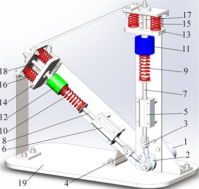
While designing and implementing such vibro-impact systems, the special attention must be paid to substantiation of the inertial, stiffness, design and excitation parameters in accordance with the specific operational conditions in order to ensure the maximal locomotion speed and the minimal energy consumption. To solve the stated problem let us consider the corresponding kinematic diagram of the semidefinite vibro-impact system (Fig. 1(b)). The driving mechanism consists of the crank DA joined with the connecting rods AB and AC. The angular velocity of the crank is considered to be constant. The connecting rods AB and AC are hinged to the sliders B and C. The corresponding springs are characterized by the stiffness coefficients , , , , and damping coefficients , , , . The impact bodies are modelled as spring-loaded sliders (oscillating masses) , . The robot’s body is characterized by the mass .
3. Differential equations describing the system motion
The studied semidefinite vibro-impact system is characterized by three degrees of freedom. The robot’s body (mass ) is considered to move translationally along a rough horizontal plane in the direction of the axis. The sliders B and C are driven by the crank mechanism rotating at the constant angular velocity . The sliders set the masses , into the oscillatory motion along the axes and , respectively. The system of differential equations describing the motions of all the bodies is following:
where , , are the coordinate, velocity and acceleration of the mass moving along the axis ; , , are the coordinate, velocity and acceleration of the mass moving along the axis ; , are the coordinate and velocity of the slider B moving along the axis ; , are the coordinate and velocity of the slider C moving along the axis ; , are the coordinate and velocity of the plate E moving along the axis ; , are the coordinate and velocity of the plate H moving along the axis ; is the acceleration of the robot’s body moving along the axis ; , are the functions describing the change of damping coefficients of the springs 16 and 15 during the impacts of the bodies 12–14 and 11–13, respectively (see Fig. 1(a)); , are the functions describing the change of stiffness coefficients of the springs 16 and 15 during the impacts of the bodies 12–14 and 11–13, respectively (see Fig. 1(a)); is the dry friction force acting upon the robot’s body during its sliding along a rough horizontal plane.
The coordinate of the slider B moving along the axis and driven by the crank DA rotating at the constant angular velocity can be determined as follows:
where , are the lengths of the rods DA and AB, respectively.
The coordinate of the slider C moving along the axis and driven by the crank DA rotating at the constant angular velocity can be determined as follows:
where is the length of the rod AC.
The functions describing the change of damping and stiffness coefficients of the springs 16 and 15 during the impacts of the bodies 12, 14, and 11, 13, respectively, are following:
The dry friction force acting upon the robot’s body during its sliding along a rough horizontal plane can be determined as follows:
where is the function describing the change of the kinetic friction force acting upon the robot’s body during its sliding along a rough horizontal plane; is the function describing the change of all the internal inertial forces acting upon the robot’s body in the axis direction; is the velocity of the robot’s body (mass ).
The kinetic friction force can be described by the following function:
where is the coefficient of kinetic (sliding) friction.
The function describing the change of all the internal inertial forces acting upon the robot’s body in the axis direction can be written as follows:
Substituting Eq. (2)–(7) into Eq. (1), the mathematical model describing forced oscillations of the semidefinite vibro-impact system can be developed.
4. Results of numerical modeling
In order to verify the correctness of the developed mathematical model let us carry out simulation of the system motion in MathCad software. In accordance with the 3D model of the vibro-impact system designed in SolidWorks software, let us specify the following parameters: 1 kg, 0.1 kg, 0.08 kg, 0.02 m, 0.06 m, 50° = 0.873 rad, 107 N/m, 103 N/m, 0 (N∙s)/m; 100 rad/s, 0.06 m, 0.2.
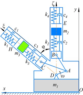
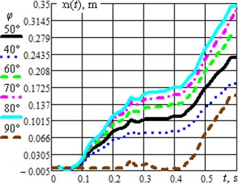
Fig. 2(a) presents the time dependencies of displacements of the impact bodies (masses and ); the masses are set into oscillatory motion due to the crank rotation at a constant angular velocity. The operation of the vibro-impact system causes the translational motion of the robot’s body whose displacement changes in time according to the dependences presented in Fig. 2(b); the simulation was carried out for different values of the angle : 40°, 50°, 60°, 70°, 80°, 90°. Based on the obtained results, it can be concluded that the average speed of the robot’s body motion reaches its maximal value at the angle 80°. Further increase of the inclination angle over 85…90° causes reduction of the average translational speed.
Fig. 2Dynamic behavior of the semidefinite vibro-impact system under the specified operational conditions and design parameters: a) displacements of the impact bodies; b) displacements of the robot’s body at different angles φ
a)
b)
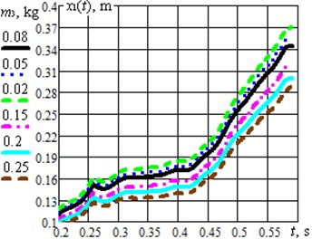
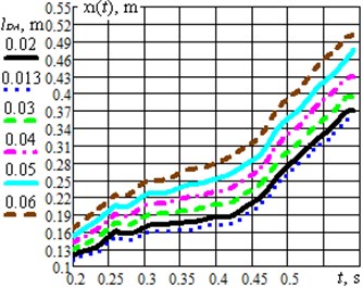
Fig. 3Results of modelling the system motion under different excitation conditions and design parameters: a) the case of changing the impact mass; b) the case of changing the crank length
a)
b)
During further optimization of the studied system it is necessary to consider the possibilities of maximization of the robot translational speed by changing the design and excitation parameters. As the first example, let us consider the change of the impact mass at the optimal angle 80° (Fig. 3(a)). The gradual increase of the mass from 0.08 kg to 0.25 kg causes the reduction of the robot average translational speed, whereas the decrease of the mass to 0.02 kg ensures the maximal value of the speed. One more parameter effecting the robot speed is the driving mechanism eccentricity value, or the length of the driving crank . The simulation showed that the optimal values 80°, 0.02 kg provide the quickest motion of the robot’s body under the condition of 0.06 m (Fig. 3(b)). The larger value of eccentricity is ensured, the larger robot average speed can be reached.
Further investigations on the subject of the paper should include the analysis and solution of the system optimization problem. The latter consists in maximizing the robot’s body average speed and minimizing the power consumption :
5. Conclusions
The paper substantiates the possibilities of implementation of a crank mechanism for exciting oscillations of a double-mass vibro-impact system setting into planar locomotion a robot’s movable body. The improved design of a semidefinite vibro-impact system is proposed, and the corresponding kinematic diagram is developed. The system consists of two impact bodies (internal masses); one mass moves along a vertical axis, whilst the other one moves along an inclined axis. The masses are spring-loaded and set into the oscillatory motion be the crank excitation mechanism. The maximal displacements of the masses are limited by the spring-loaded impact plates. The kinetic energy being released during the impact of the bodies and the plates causes both the reduction of the vertical force exerted by the robot’s body upon the supporting surface, and the sliding of the robot’s body along the surface.
The studied semidefinite vibro-impact system is characterized by three generalized coordinates (degrees of freedom): two of them describe the translational motions of the impact bodies along the corresponding guide axes, and the last one considers the translational motion of the robot’s body along a rough horizontal surface. Based on the developed mathematical model of forced oscillation of the studied semidefinite vibro-impact system, the simulation of the impact masses and the robot’s body motions is carried out in MathCad software. All the input parameters are specified in accordance with the 3D model of the vibro-impact system designed in SolidWorks software. The results of simulation of the system dynamic behavior allowed to draw the conclusions about the certain optimal design and excitation parameters: the optimal angle between the guide axes of the impact bodies 80°, the optimal value of the inclined impact mass 0.02 kg, the optimal driving mechanism eccentricity value (the length of the driving crank) 0.06 m.
References
-
Rao S. S., Mechanical Vibrations. Sixth Edition in SI Units. Harlow, United Kingdom: Pearson Education Limited, 2018.
-
X. Zhan, J. Xu, and H. Fang, “Planar locomotion of a vibration-driven system with two internal masses,” Applied Mathematical Modelling, Vol. 40, No. 2, pp. 871–885, Jan. 2016, https://doi.org/10.1016/j.apm.2015.06.016
-
Fritzkowski P. and Starosta R., “Dynamics of an inertially driven robot,” Vibrations in Physical Systems, Vol. 29, pp. 1–9, 2018.
-
Y. Yan, Y. Liu, and M. Liao, “A comparative study of the vibro-impact capsule systems with one-sided and two-sided constraints,” Nonlinear Dynamics, Vol. 89, No. 2, pp. 1063–1087, Jul. 2017, https://doi.org/10.1007/s11071-017-3500-7
-
P. Li and Z. Jiang, “Bifurcation analysis of stick-slip motion of the vibration-driven system with dry friction,” Mathematical Problems in Engineering, Vol. 2018, No. 3, pp. 1–10, Aug. 2018, https://doi.org/10.1155/2018/2305187
-
B. Bardin and A. Panev, “On dynamics of a rigid body moving on a horizontal plane by means of motion of an internal particle,” Vibroengineering PROCEDIA, Vol. 8, pp. 135–141, Oct. 2016, https://doi.org/10.1063/1.5034582
-
K. Ragulskis, B. Spruogis, M. Bogdevičius, A. Matuliauskas, V. Mištinas, and L. Ragulskis, “Motion of vibration manipulators with self stopping device in one direction with interactions of two non deformable elements in one direction,” Mechanics, Vol. 26, No. 6, pp. 526–531, Dec. 2020, https://doi.org/10.5755/j01.mech.26.6.25527
-
K.-T. Nguyen, N.-T. La, K.-T. Ho, Q.-H. Ngo, N.-H. Chu, and V.-D. Nguyen, “The effect of friction on the vibro-impact locomotion system: modeling and dynamic response,” Meccanica, Vol. 56, No. 8, pp. 2121–2137, Aug. 2021, https://doi.org/10.1007/s11012-021-01348-w
-
N.-T. La, T.-T. Nguyen, and V.-D. Nguyen, “A comparative study on the two vibration driven locomotion systems in various friction levels,” Vietnam Journal of Mechanics, Vol. 43, pp. 121–137, Apr. 2021, https://doi.org/10.15625/0866-7136/15662
-
V. Korendiy, “Dynamics of two-mass mobile vibratory robot with electromagnetic drive and vibro-impact operation mode,” Ukrainian Journal of Mechanical Engineering and Materials Science, Vol. 4, No. 2, pp. 80–93, 2018, https://doi.org/10.23939/ujmems2018.02.080
-
V. Gursky, I. Kuzio, and V. Korendiy, “Optimal synthesis and implementation of resonant vibratory systems,” Universal Journal of Mechanical Engineering, Vol. 6, No. 2, pp. 38–46, Mar. 2018, https://doi.org/10.13189/ujme.2018.060202
-
O. Lanets, O. Kachur, V. Korendiy, and V. Lozynskyy, “Controllable crank mechanism for exciting oscillations of vibratory equipment,” in Lecture Notes in Mechanical Engineering, pp. 43–52, 2021, https://doi.org/10.1007/978-3-030-77823-1_5
Cited by
About this article

