Abstract
Vibration-driven locomotion principles are currently of significant interest among designers and researchers dealing with mobile robotics. Among a great variety of robots chasses, the wheeled ones are the most commonly used. The major purpose of this study consists in defining the dynamic characteristics of the wheeled vibration-driven robot equipped with the centrifugal (inertial) vibration exciter (unbalanced rotor) and overrunning clutches ensuring the robot’s wheels rotation in one direction. The research methodology is divided into three basic stages: developing the robot’s dynamic diagram and deriving the motion equations followed by numerical modeling in the Mathematica software; designing the 3D-model and simulating the robot motion in the SolidWorks software; creating the experimental prototype and conducting the full-scale tests. The obtained results show the time dependencies of the robot’s body acceleration, speed, and displacement at certain operational conditions. The main scientific novelty of the paper resides in substantiating the relationships between the robot’s design parameters and its dynamic characteristics under different operational conditions. The performed investigations can be useful for researchers and designers dealing with vibration-driven robots, capsule-type locomotion systems, pipelines inspecting vehicles, etc.
Highlights
- The paper considers the dynamics of a wheeled vibration-driven robot with the centrifugal vibration exciter (unbalanced rotor) and overrunning clutches ensuring the wheels rotation in one direction.
- The results of numerical modeling, computer simulation, and experimental investigations showed that the robot average locomotion speed reaches 130 mm/s at the forced frequency of 89 rad/s (850 rpm).
- The performed investigations can be useful for researchers and designers dealing with vibration-driven robots, capsule-type locomotion systems, pipelines inspecting vehicles, etc.
1. Introduction
Mobile robotics is a relatively young branch of scientific research. In most cases, mobile robots and other vehicles use wheeled or tracked (caterpillar) chasses with an active transmission connecting the motor (or engine) with the corresponding actuators (wheels, tracks, etc.). In distinction to the classical vehicles’ designs, mobile robots are sometimes equipped with vibration-driven locomotion systems. One of the most widespread locomotion principles is based on the anisotropic friction conditions occurring when two bodies are in contact and move relative to one another. This phenomenon is comprehensively studied in numerous publications, particularly in [1, 2], which are dedicated to theoretical and experimental research on the mobile robot’s dynamic behavior under friction-induced stick-slip locomotion conditions. In [3], the authors studied the influence of the excitation conditions frequency and duration of the pulse-width signal) on the average translational speed of the vibration-driven capsule-type robot. The bifurcation analysis of the stick-clip locomotion of a similar vibration-driven system is studied in [4], taking into account different dry friction conditions. In [5, 6], the authors considered the possibilities of optimizing the control algorithms of the vibration-driven robots in order to maximize their translational speed and minimize power consumption. The papers [7, 8] are devoted to improving the locomotion systems of the vibration-driven capsule-type robots and to investigating the friction influence on the robot’s oscillatory system dynamic response.
The initial idea of this paper is based on the investigations presented in [9, 10, 11], in which an interesting design of the wheeled robot driven by the centrifugal vibration exciter was proposed. This design idea acquired further development in the papers [12, 13, 14], where the improved crank-type exciter was implemented in the robot’s drive in order to provide efficient vibro-impact locomotion conditions. The possibilities of equipping the in-pipe vibration-driven robot with the centrifugal (inertial) exciter (unbalanced rotor) are thoroughly studied in [15, 16]. The major purpose of this study consists in defining the dynamic characteristics of the wheeled robot equipped with the centrifugal vibration exciter (unbalanced rotor) and overrunning clutches ensuring the robot’s wheels rotation in one direction.
2. Research methodology
2.1. 3D-model of vibratory conveyor
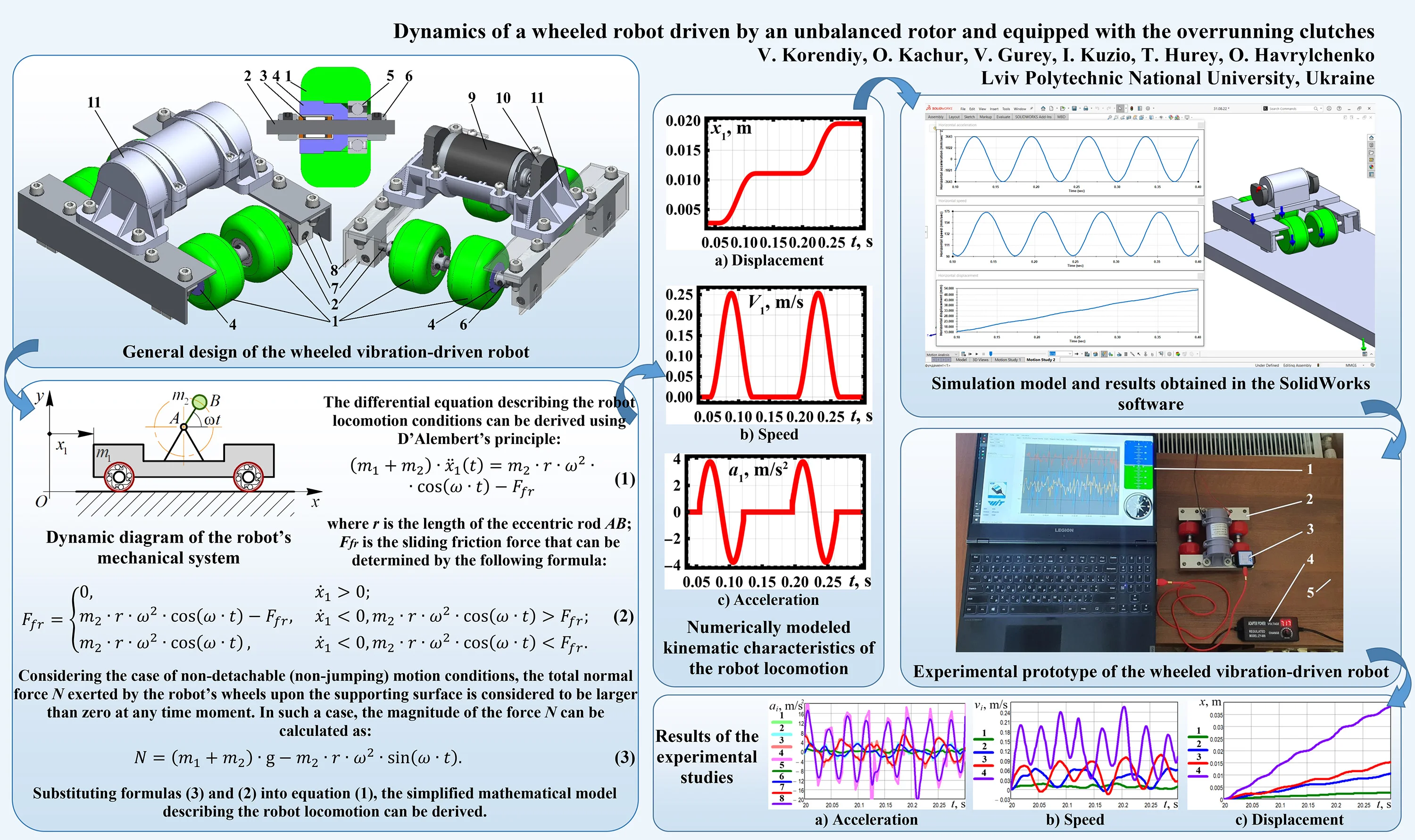
The proposed design of the wheeled vibration-driven robot is shown in Fig. 1. The robot consists of four rubber wheels 1 which are in contact with the horizontal supporting surface. The front and rear wheels 1 are installed on the corresponding axes 2 with the help of the overrunning (free-wheel) clutches 3 using the bushings (bosses) 4. The clutches 3 allow the unidirectional (single-way) rotation of the wheels 1. Additionally, the ball bearings 5 are used to join the wheels 1 with the axes 2 and to hold the extra loading. In order to eliminate the wheels sliding along the axes 2, the clamps 6 are used. The axes 2 are fixed to the angles 8 of the robot’s body with the help of the clamps 7. The DC electric motor 9 with the unbalanced rotor 10 is installed in the housing 11, which is fixed to the angles 8. The centrifugal forces generated due to the unbalanced masses rotation act through the motor 9 upon the housing 11 and cause the pushing effect on the robot’s body. When the line of action of the centrifugal forces coincides with the direction, along which the clutches 3 allow the robot to move, the wheels 1 start rotating. On the other hand, when the centrifugal forces are characterized by the opposite direction, the clutches 3 block (restrain) the wheels 1, and the robot remains at rest.
Fig. 1General design of the wheeled vibration-driven robot
2.2. Dynamic diagram of the robot and differential equation of its locomotion
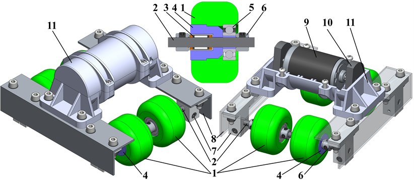
The simplified dynamic diagram of the robot’s mechanical system is presented in Fig. 2. The robot of the mass moves along a straight horizontal surface due to the action of centrifugal forces generated by the mass rotating around the hinge at the constant angular speed . The inertial coordinate system is related with the unmovable surface. The generalized coordinate is adopted for describing the robot’s horizontal displacement. The wheels are connected to the robot’s body with the help of the overrunning (free-wheel) clutches being engaged in one direction and free in the other. Therefore, the wheels are allowed to rotate in a clockwise direction, and the robot can move to the right. The leftward motion of the robot is not possible because the wheels become blocked (restrained) by the overrunning clutches. Let us assume that the contact between the wheels and the surface is ideal, i.e., there is no rolling friction for the clockwise rotation of the wheels, while the counterclockwise rotation is restricted. Herewith, the sliding friction coefficient is equal to . Any energy losses and viscous friction effects are also assumed to be negligibly small.
Fig. 2Dynamic diagram of the robot’s mechanical system
The differential equation describing the robot locomotion conditions can be derived using D’Alembert’s principle:
where is the length of the eccentric rod (see Fig. 2); is the sliding friction force that can be determined by the following formula:
Considering the case of non-detachable (non-jumping) motion conditions, the total normal force exerted by the robot’s wheels upon the supporting surface is considered to be larger than zero at any time moment. In such a case, the magnitude of the force can be calculated as:
Substituting formulas Eqs. (3) and (2) into Eq. (1), the simplified mathematical model describing the robot locomotion can be derived.
2.3. Experimental technique and equipment
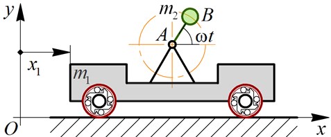
The experimental prototype of the wheeled vibration-driven robot has been implemented in practice at the Vibroengineering Laboratory of Lviv Polytechnic National University. It totally corresponds to the 3D-model designed in the SolidWorks software and described above (see Fig. 1). The general photo of all the equipment used for conducting the experimental studies on the robot locomotion conditions is presented in Fig. 3. In order to register the data obtained from the acceleration sensor 3 (WitMotion WT901CL), the corresponding WitMotion software has been installed on the laptop 1. The accelerometer uses the USB Type-C connection interface and allows for registering the robot’s acceleration at the retrieval rate of 200 measurements per second and the baud rate of 115200. The robot 2 moves along the flat horizontal surface 5 due to the application of the periodic disturbing force generated by the inertial exciter (unbalanced rotor). The forced frequency (the angular speed of the rotor) is changed by means of regulating the voltage supplied to the DC motor that actuates the unbalanced rotor. In this case, the controllable voltage adapter 4 (ZY-009) has been used to change the voltage from 0 V to 24 V and to regulate the robot’s translational speed. The corresponding relationships allowing for determining the forced frequency (the unbalanced rotor angular speed) at the given voltage value have been established by performing numerous starts of the DC electric motor.
Fig. 3Experimental prototype of the wheeled vibration-driven robot
3. Results and discussion
3.1. Numerical modeling of the robot locomotion in the Mathematica software
Let us perform the robot locomotion numerical modeling in the Mathematica software using the integrated Runge-Kutta methods. The following input parameters have been adopted: 1.05 kg, 0.1 kg, 0.028 m, 89 rad/s (850 rpm), 0.7. The obtained results are shown in Fig. 4 in the form of time response curves and time dependencies of the robot’s speed and acceleration. The numerical modeling showed that the robot passed a distance of about 0.02 m during two cycles of its stepwise locomotion, i.e., during 0.15 s. The speed varies in the range of 0…0.26 m/s, while its average value equals 0.13 m/s. The acceleration changes from –4 m/s2 to 4 m/s2. It is observed that the robot’s speed does not take negative values.
Fig. 4Numerically modeled kinematic characteristics of the robot locomotion
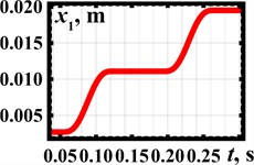
a) Displacement
b) Speed
c) Acceleration
3.2. Simulation of the robot motion in the SolidWorks software
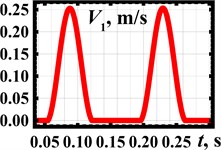
The robot’s simulation model is presented in Fig. 5. The geometrical and inertial characteristics and the operational parameters are similar to those adopted earlier. The robot can move to the right, while its leftward motion is functionally restricted. The unbalanced rotor rotates at the forced frequency of 850 rpm in the clockwise direction. During the time interval of 0.3 s, the robot’s body has passed a distance of about 40 mm. This fact allows for concluding that its average speed exceeds 130 mm/s. The maximal and minimal values of the robot’s translational speed are equal to 90 mm/s and 175 mm/s, respectively. The acceleration of the robot’s body changes in the range of –3643…3643 mm/s2. The simulation results satisfactorily agree with the ones obtained during the numerical modeling in the Mathematica software.
Fig. 5Simulation model and results obtained in the SolidWorks software
3.3. Results of experimental investigations
The following forced frequencies have been accepted to perform experimental studies: 48 rad/s (460 rpm), 73 rad/s (700 rpm), 103 rad/s (980 rpm), 167 rad/s (1600 rpm). The experimental results showing the time dependences of the robot’s body accelerations at different forced frequencies are presented in Fig. 6(a). The curves 1, 2, 3, 4 present the data obtained from the accelerometer and registered in the WitMotion software. The curves 5, 6, 7, 8 correspond to the previous four ones and show the experimental data that have been numerically interpolated in the MathCad software. The larger values of accelerations of about 16…20 m/s2 are obtained at the largest forced frequency of 167 rad/s (1600 rpm) (curves 4 and 8). The smallest values that do not exceed 1…1.5 m/s2 correspond to the smallest forced frequency of 48 rad/s (460 rpm) (curves 1 and 5). Numerical interpolation and integration of the experimental data were performed in the MathCad software. This allowed for obtaining the time dependencies of the robot speed and displacement presented in Fig. 6(b-c). The largest speed of about 0.2…0.25 m/s is observed at the forced frequency of 167 rad/s (1600 rpm) (curve 4). The lowest speed does not exceed 0.02 m/s at 48 rad/s (460 rpm) (curve 1). Considering the time interval of 20…20.3 s, when the robot reached the steady-state locomotion conditions, it passed the distance of about 0.038 m at the largest forced frequency and the distance of 0.003 m at the smallest one. Therefore, based on the experimental investigations, the robot’s average speed varies in the range of 0.01…0.127 m/s.
Fig. 6Results of the experimental studies
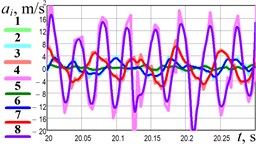
a) Acceleration
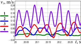
b) Speed
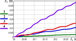
c) Displacement
4. Conclusions
The presented research is devoted to investigating the dynamic behavior and kinematic characteristics of the vibration-driven robot equipped with the inertial (centrifugal) exciter and unidirectionally rotating wheels. The results of numerical modeling, computer simulation, and experimental investigations showed that the robot’s average locomotion speed is about 130 mm/s at the forced frequency of 89 rad/s (850 rpm). The robot’s body acceleration changes within –4…4 m/s2. The performed studies can be useful for researchers and designers dealing with vibration-driven robots, capsule-type systems, pipelines inspecting vehicles, etc. The prospects of further research consist in substantiating the robot’s inertial and excitation parameters to maximize its translational speed and minimize the consumed power.
References
-
Z. Du, H. Fang, X. Zhan, and J. Xu, “Experiments on vibration-driven stick-slip locomotion: A sliding bifurcation perspective,” Mechanical Systems and Signal Processing, Vol. 105, pp. 261–275, May 2018, https://doi.org/10.1016/j.ymssp.2017.12.001
-
J. Xu and H. Fang, “Improving performance: recent progress on vibration-driven locomotion systems,” Nonlinear Dynamics, Vol. 98, No. 4, pp. 2651–2669, Dec. 2019, https://doi.org/10.1007/s11071-019-04982-y
-
A. Nunuparov, F. Becker, N. Bolotnik, I. Zeidis, and K. Zimmermann, “Dynamics and motion control of a capsule robot with an opposing spring,” Archive of Applied Mechanics, Vol. 89, No. 10, pp. 2193–2208, Oct. 2019, https://doi.org/10.1007/s00419-019-01571-8
-
P. Li and Z. Jiang, “Bifurcation analysis of stick-slip motion of the vibration-driven system with dry friction,” Mathematical Problems in Engineering, Vol. 2018, pp. 1–10, Aug. 2018, https://doi.org/10.1155/2018/2305187
-
B. Diao, X. Zhang, H. Fang, and J. Xu, “Bi-objective optimization for improving the locomotion performance of the vibration-driven robot,” Archive of Applied Mechanics, Vol. 91, No. 5, pp. 2073–2088, May 2021, https://doi.org/10.1007/s00419-020-01870-5
-
B. Diao, X. Zhang, H. Fang, and J. Xu, “Optimal control of the multi-module vibration-driven locomotion robot,” Journal of Sound and Vibration, Vol. 527, p. 116867, Jun. 2022, https://doi.org/10.1016/j.jsv.2022.116867
-
V. Du Nguyen and N. T. Lam, “An improvement of vibration-driven locomotion module for capsule robots,” Mechanics Based Design of Structures and Machines, Vol. 49, No. 7, pp. 1–15, 2020.
-
K.-T. Nguyen, N.-T. La, K.-T. Ho, Q.-H. Ngo, N.-H. Chu, and V.-D. Nguyen, “The effect of friction on the vibro-impact locomotion system: modeling and dynamic response,” Meccanica, Vol. 56, No. 8, pp. 2121–2137, Aug. 2021, https://doi.org/10.1007/s11012-021-01348-w
-
I. A. Loukanov and S. P. Stoyanov, “Experimental determination of dynamic characteristics of a vibration-driven robot,” IOSR Journal of Mechanical and Civil Engineering, Vol. 12, No. 4, pp. 62–73, 2015, https://doi.org/10.9790/1684-12426273
-
I. A. Loukanov, V. G. Vitliemov, and I. V. Ivanov, “Dynamics of a mobile mechanical system with vibration propulsion (VibroBot),” International Journal of Research in Engineering and Science, Vol. 4, No. 6, pp. 44–51, 2016.
-
I. A. Loukanov, V. G. Vitliemov, and I. V. Ivanov, “Dynamics of a vibration-driven one-way moving wheeled robot,” IOSR Journal of Mechanical and Civil Engineering, Vol. 13, No. 3, pp. 14–22, 2016, https://doi.org/10.9790/1684-1303051422
-
V. Korendiy, V. Gursky, O. Kachur, P. Dmyterko, O. Kotsiumbas, and O. Havrylchenko, “Mathematical model and motion analysis of a wheeled vibro-impact locomotion system,” Vibroengineering Procedia, Vol. 41, pp. 77–83, Apr. 2022, https://doi.org/10.21595/vp.2022.22422
-
V. Korendiy et al., “Motion simulation and impact gap verification of a wheeled vibration-driven robot for pipelines inspection,” Vibroengineering Procedia, Vol. 41, pp. 1–6, Apr. 2022, https://doi.org/10.21595/vp.2022.22521
-
V. Korendiy, O. Kachur, V. Gursky, V. Gurey, R. Pelio, and O. Kotsiumbas, “Experimental investigation of kinematic characteristics of a wheeled vibration-driven robot,” Vibroengineering Procedia, Vol. 43, pp. 14–20, Jun. 2022, https://doi.org/10.21595/vp.2022.22721
-
V. Korendiy, O. Kotsiumbas, V. Borovets, V. Gurey, and R. Predko, “Mathematical modeling and computer simulation of the wheeled vibration-driven in-pipe robot motion,” Vibroengineering Procedia, Vol. 44, pp. 1–7, Aug. 2022, https://doi.org/10.21595/vp.2022.22832
-
V. Korendiy, O. Kachur, V. Gurey, R. Predko, R. Palash, and O. Havrylchenko, “Simulation and experimental investigation of kinematic characteristics of the wheeled in-pipe robot actuated by the unbalanced rotor,” Vibroengineering Procedia, Vol. 45, pp. 8–14, Oct. 2022, https://doi.org/10.21595/vp.2022.22971
Cited by
About this article

The authors have not disclosed any funding.
The datasets generated during and/or analyzed during the current study are available from the corresponding author on reasonable request.
The authors declare that they have no conflict of interest.
