Abstract
Mobile robotic systems are currently of significant interest due to the wide range of possible applications. Among a great variety of mobile robots, specific attention is paid to the wheeled ones. The main purpose of this research consists in substantiating the possibilities of improving the vibration-driven robot equipped with the unidirectionally rotating wheels. The methodology of the present study contains the development of the robot’s 3D-model in the SolidWorks software, constructing the simplified dynamic diagram of the robot’s oscillatory system, and developing its simulation model in the MapleSim software. The research results are obtained by numerical solving of the motion equations in the MapleSim software, by simulating the robot locomotion conditions in the SolidWorks software, and by conducting experiments. The results present the main kinematic characteristics of the robot motion under different operational conditions. The major scientific novelty of this paper consists in developing the improved design of the wheeled robot driven by the centrifugal (inertial) vibration exciter and substantiating its operational peculiarities. The obtained results can be effectively used while creating the production prototypes of mobile robotic systems, particularly those for cleaning the pipelines and monitoring (inspecting) their inner surfaces, welds, joints, couplings, etc.
Highlights
- The novel design of the wheeled vibration-driven in-pipe robot is developed based on the eight-wheel rocker-type mechanism actuated by the unbalanced rotor with controllable angular frequency.
- The computer simulation of the robot operation was carried out using MapleSim and SolidWorks software and substantiated the stepwise and jump-wise locomotion conditions of the robot’s body.
- The experimental prototype of the robot was implemented in practice and tested inside the rectangular-shaped box. The obtained experimental results totally agree with the simulation ones.
1. Introduction
Mobile robotic systems are currently widely used in different fields of industry and are becoming more and more important in the daily life of people all over the world. The locomotion principles of mobile robots are of a great variety: wheeled, caterpillar (tracked), walking (stepping), jumping, sliding, etc. In most cases, electric motors are used for driving the robots’ wheels, caterpillars, or other movers using the additional transmission system. Such mobile robots are currently well-studied and manufactured by numerous companies worldwide. In contrast to traditional robots designs, another prospective direction of mobile robotics is being actively developed. It deals with the vibration-driven locomotion principles. In such cases, the robots are not equipped with the active transmission, and instead of it, the certain vibration exciter is used. The so-called stick-slip locomotion is usually generated due to the anisotropic (non-homogeneous) dry friction phenomena occurring between the contacting bodies that move relative to each other [1]. In the mentioned paper, the authors presented the results of comprehensive theoretical and experimental investigations on the dynamics of the dry friction-induced stick-slip locomotion of a mobile robot sliding along a rough surface.
In the paper [2], the authors investigated the average translational velocity of the capsule-type vibration-driven robot under different excitation conditions (the period and the pulse duration of the pulse-width excitation signal). A similar vibration-driven system is studied in [3] from the viewpoint of bifurcation analysis of its stick-clip locomotion under the conditions of dry friction. The paper [4] is focused on the optimization of the control algorithms for maximizing the translational speed and minimizing the power consumption of the vibration-driven robots. In [5, 6], the authors proposed an improved locomotion system for capsule-type robots, studied the friction effects on the system’s dynamic response, and investigated the robot’s motion conditions on the inclined track. A separate direction of investigations of the stick-slip locomotion is dedicated to the anisotropic friction conditions ensuring this locomotion. In particular, the research [7] analysed the influence of the piecewise smooth nonholonomic constraints on the dynamic behaviour of vibration-driven systems.
An interesting design of the in-pipe vibration-driven robot is proposed in [8]. The walking robot is based on the double-mass oscillatory system driven by the twin centrifugal (inertial) vibration exciter, whose unbalanced rotors are synchronized by the non-circular gear transmission. Unlike the walking locomotion principles, the wheeled drives are more widely used in mobile robotics. The major idea of the present research has originated on the basis of the investigations presented in [9, 10]. In these papers, the authors proposed a novel design and studied the dynamic behaviour of the mobile (wheeled) robot equipped with the centrifugal (inertial) vibration exciter and unidirectionally rotating wheels. This idea has been improved (modernized) in the papers [11, 12], where the authors proposed to use the vibro-impact operational conditions by implementing the enhanced crank-type exciter into the robot’s drive in order to improve its operational efficiency. The present paper continues the authors’ previous investigations initiated in [13] and is focused on developing the improved design of the transformable wheeled robot driven by the centrifugal (inertial) vibration exciter and equipped with the overrunning clutches providing the unidirectional rotation of the robot’s wheels.
2. Research methodology
2.1. General design of the mobile robot
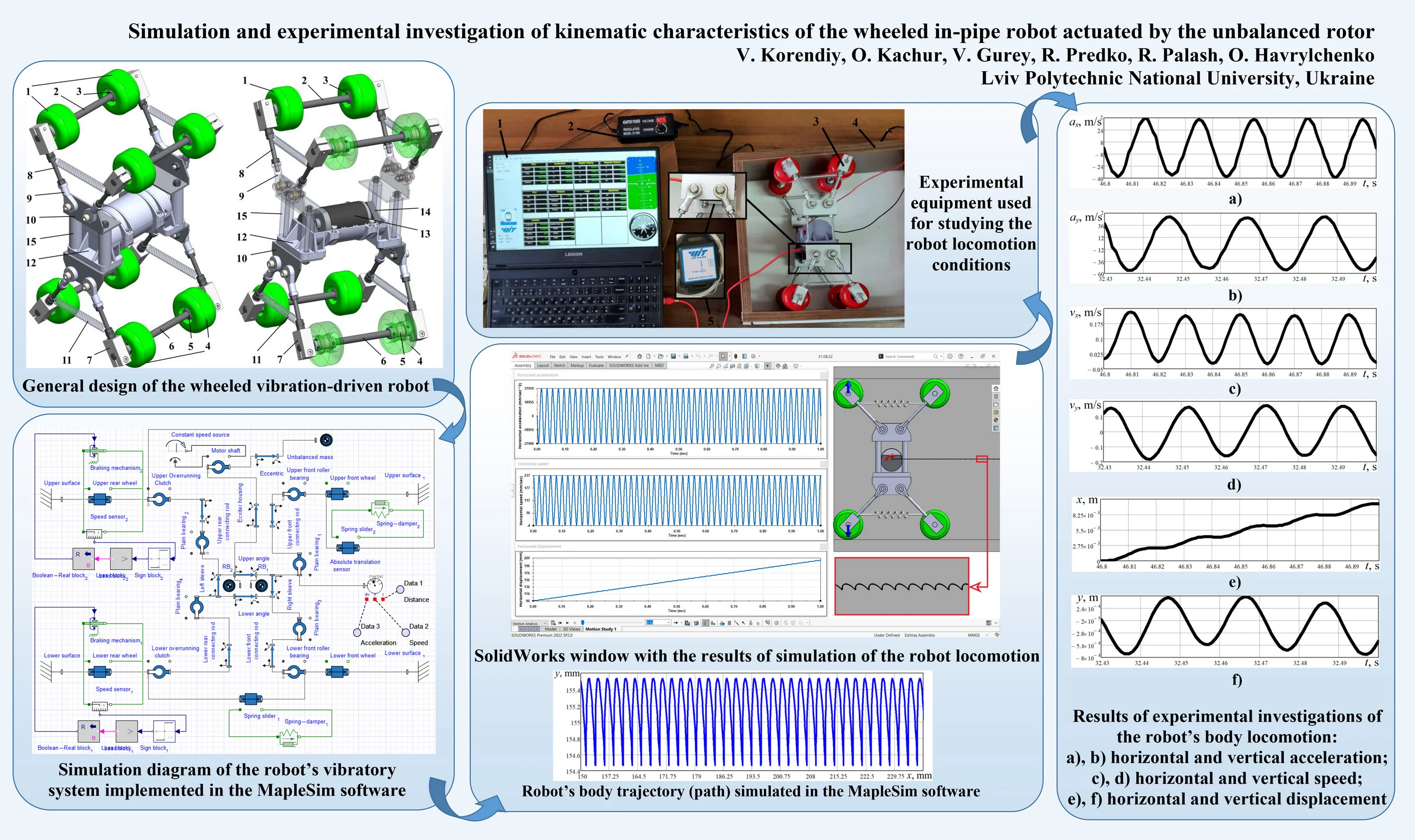
The improved design of the wheeled robot is shown in Fig. 1. The rubber wheels are contacting with the inner surfaces of the pipe or tube. The front wheels 1 are installed on the axis 2 with the help of the roller bearings 3. The rear wheels 4 are joined with the corresponding axis 6 by the overrunning (free-wheel) clutches 5 allowing their unidirectional (single-way) rotation.
Fig. 1General design of the wheeled vibration-driven robot
The axes 2 and 6 are fixed by the clamps 7 to the connecting rods 8. The latter are joined by the plain bearings 9 to the angles 10, on which the body (housing) 12 of the inertial exciter is installed. The exciter consists of the DC electric motor 13 and the unbalanced masses 14 fixed to the motor’s shaft on its both ends. Two pairs of cylindrical coil tension springs 11 are installed between the front and rear clamps of the robot’s wheels axes. In order to adjust the motor’s unbalanced shaft to coincide with the geometrical centreline of a tube (pipe), the upper and lower wheeled systems are connected with each other by the distance (spacing) sleeves 15.
The rotation of the motor’s shaft and the unbalanced masses causes the generation of the inertial (centrifugal) forces acting upon the body (housing) 12. The latter performs oscillations in a vertical plane. When the body 12 moves down, the lower rear wheels become blocked, and the upper rear wheels move forward along the upper inner surface of the pipe (tube) due to the application of the overrunning clutches. When the housing 12 moves up, the upper rear wheels become blocked, while the lower rear ones move forward. In such a way, the robot performs stepwise translational locomotion along a pipe or tube.
2.2. Dynamic diagram of the robot’s oscillatory system simulated in MapleSim software
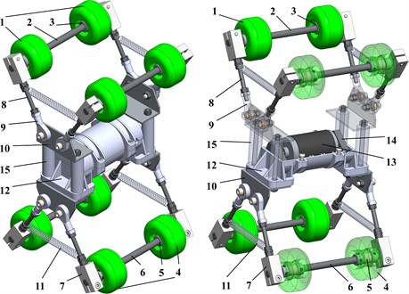
Considering numerous scientific papers, the dynamic behaviour of various physical systems is usually simulated with the help of various software. Let us use the MapleSim program to study the motion conditions of the wheeled vibration-driven robot. Its simulation model is presented in Fig. 2. The constant speed source sets the motor’s shaft into motion. The eccentric rod (crank) is fixed to the motor shaft, and the unbalanced mass is joined to the rod’s free end. The motor is installed in the housing mounted on the robot’s body. The latter consists of the lower and upper angles and the left and right sleeves. The mass of the robot’s body is simulated as two rigid bodies (RB1, RB2) placed symmetrically with respect to the upper angle. Four connecting rods are joined with the robot’s body by corresponding plain bearings. The free ends of the rods are fixed to the wheeled axes by the clamps. The upper and lower front wheels (simulated as sliders) are installed on the corresponding axes with the help of roller bearings.
Fig. 2Simulation diagram of the robot’s vibratory system implemented in the MapleSim software
The rear wheels are connected to the rear axes using the overrunning clutches. In order to simulate the clutches, the corresponding braking mechanisms have been constructed. The speed sensors and sign-blocks are used to define the motion direction of the wheels (sliders). Then, the less-block compares the speed value with zero. If the speed has a negative sign, the Boolean-real block sends the signal to the braking mechanism for stopping (restraining) the wheel.
The centrifugal forces generated during the unbalanced mass rotation cause the translational locomotion of the robot’s body. Due to the application of the braking mechanisms (overrunning clutches) in the rear wheels and the spring-dumper elements between the front and rear axes, the robot moves along a horizontal axis and performs the oscillations in a vertical direction. To determine the kinematic parameters of the robot’s body, the absolute translation sensor is used, allowing for registering its instantaneous displacement, speed, and acceleration in any direction.
3. Results and discussion
3.1. Simulation of the robot motion in the MapleSim and SolidWorks software
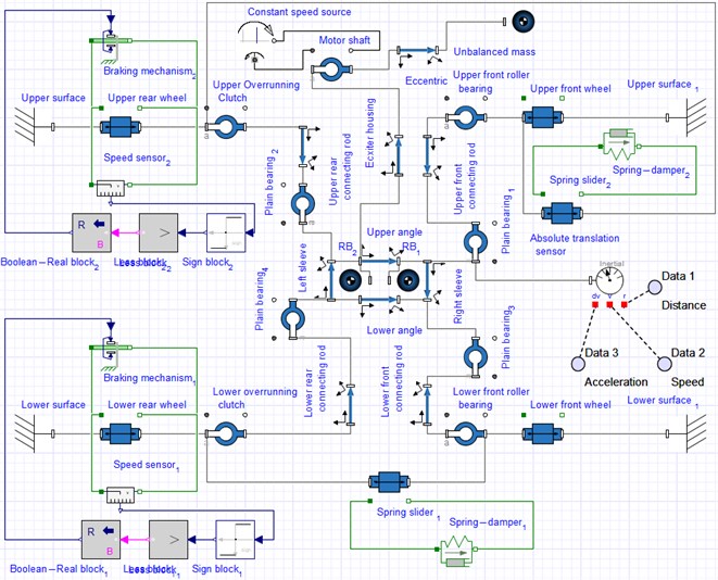
The simulation of the robot’s locomotion has been carried out both in the MapleSim and SolidWorks software. The obtained results present the time dependencies of the horizontal and vertical displacements, speeds, and accelerations of the robot’s body. Fig. 3 shows the SolidWorks Motion window with the simulation results. The robot moves inside the square-shaped tube with an average horizontal speed of about 120 mm/s at the forced frequency of 50 Hz (3000 rpm). The maximal horizontal speed reaches 237 mm/s, and its minimal value is –4 mm/s due to the sliding friction of the blocked wheels along the tube’s inner surfaces. The robot’s body horizontal acceleration varies in the range of –37909…37910 mm/s2. During the time period of 1 s, the robot’s body passed a distance of about 120 mm, and its trajectory (path) is characterized by a saw-like shape. Therefore, it can be stated that the implementation of the inertial vibration exciter in the form of the unbalanced rotor allows for providing the stepwise and jump-wise locomotion conditions of the robot’s body inside the square-shaped tube.
Fig. 3SolidWorks window with the results of simulation of the robot locomotion
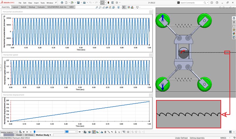
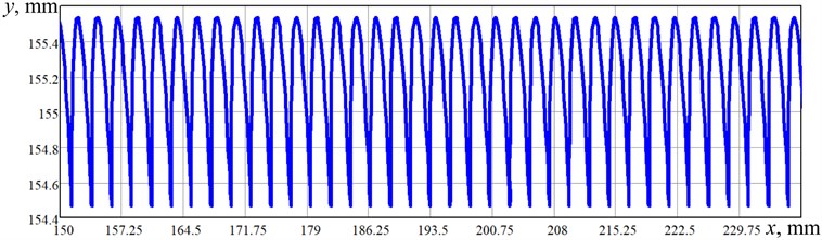
Taking into account the fact that the time dependencies of the robot kinematic parameters simulated in the SolidWorks and MapleSim software are almost the same, let us pay major attention to the robot’s body motion trajectory (path). Figure 4 shows the simulation results of the robot’s locomotion obtained in the MapleSim software. The trajectory curve (path) allows for concluding that the maximal vertical displacement of the robot’s body reaches 1 mm, and the length of one step made by the robot’s wheeled mechanism during one stepping period is about 2.4 mm. The simulation process lasted 0.75 s, and during this time, the robot passed a distance of about 90 mm. Therefore, its average horizontal locomotion speed is about 120 mm/s. The obtained results prove the previously drawn conclusions about the robot’s stepwise and jump-wise locomotion conditions simulated in the SolidWorks software.
Fig. 4Robot’s body trajectory (path) simulated in the MapleSim software
3.2. Experimental investigations of the robot motion
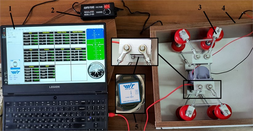
The verification of the simulation results was performed by testing the robot’s experimental prototype in the Vibroengineering Laboratory of the Department of Robotics and Integrated Mechanical Engineering Technologies of Lviv Polytechnic National University (see Fig. 5). The robot 3 was implemented in practice based on the 3D-design developed in the SolidWorks software (see Figs. 1 and 5). The laptop 1 with the installed WitMotion software was used for registering the data obtained from the accelerometer 5 fixed on the robot’s body. In order to control the forced frequency of the inertial vibration exciter (unbalanced rotor of the DC motor), the voltage regulator 2 was applied. The experimental prototype was placed inside the square-shaped box 4, and its acceleration was measured at the forced frequency of 50 Hz (3000 rpm) under the steady-state motion conditions.
Fig. 5Experimental equipment used for studying the robot locomotion conditions
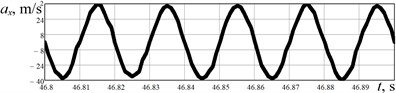
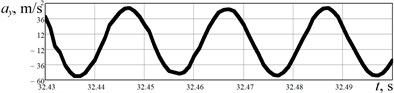
The results of experimental investigations are presented in Fig. 6. The acceleration data (Fig. 6(a), 6(b)) obtained from the WitMotion sensor was numerically integrated in the MathCad software. The robot’s body horizontal speed varies in the range of –0.01…0.24 m/s, while its average value is about 0.11 m/s. The robot’s body average horizontal displacement performed during one stepping cycle equals approximately 0.002 m. Considering the vertical acceleration, its maximal value is about 55 m/s2, and minimal one reaches –55 m/s2. The vertical speed is in the range of –0.2…0.2 m/s, and maximal displacement is about 0.001 m. Therefore, the results of experimental studies satisfactorily agree with the simulation results.
Fig. 6Results of experimental investigations of the robot’s body locomotion: a), b) horizontal and vertical acceleration; c), d) horizontal and vertical speed; e), f) horizontal and vertical displacement
a)
b)
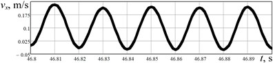
c)
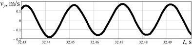
d)
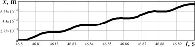
e)
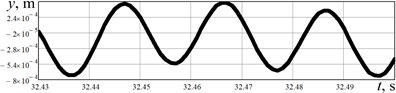
f)
4. Conclusions
The paper is focused on studying the dynamic behavior of the wheeled in-pipe robot actuated by the unbalanced rotor. While performing the investigations, the improved 3D-model of the robot was developed, the simulation models of its oscillatory system were constructed in the MapleSim and SolidWorks software, and the robot’s experimental prototype was implemented in practice. The simulation has shown that the robot moves inside the square-shaped tube with an average horizontal speed of about 120 mm/s at the forced frequency of 50 Hz (3000 rpm). The maximal horizontal speed reaches 237 mm/s, and the acceleration does not exceed 37910 mm/s2. The robot’s body average horizontal displacement performed during one stepping cycle equals approximately 2 mm. The experimental results proved the previously drawn conclusions about the robot’s stepwise and jump-wise locomotion conditions simulated in the SolidWorks and MapleSim software. The major scientific novelty of this paper consists in developing the improved design of the wheeled robot driven by the centrifugal (inertial) vibration exciter. The obtained results can be effectively used while creating the production prototypes of mobile robotic systems, particularly those for cleaning the pipelines and monitoring (inspecting) their inner surfaces, welds, joints, couplings, etc.
References
-
J. Xu and H. Fang, “Improving performance: recent progress on vibration-driven locomotion systems,” Nonlinear Dynamics, Vol. 98, No. 4, pp. 2651–2669, Dec. 2019, https://doi.org/10.1007/s11071-019-04982-y
-
A. Nunuparov, F. Becker, N. Bolotnik, I. Zeidis, and K. Zimmermann, “Dynamics and motion control of a capsule robot with an opposing spring,” Archive of Applied Mechanics, Vol. 89, No. 10, pp. 2193–2208, Oct. 2019, https://doi.org/10.1007/s00419-019-01571-8
-
P. Li and Z. Jiang, “Bifurcation analysis of stick-slip motion of the vibration-driven system with dry friction,” Mathematical Problems in Engineering, Vol. 2018, No. 12, pp. 1–10, Aug. 2018, https://doi.org/10.1155/2018/2305187
-
B. Diao, X. Zhang, H. Fang, and J. Xu, “Optimal control of the multi-module vibration-driven locomotion robot,” Journal of Sound and Vibration, Vol. 527, p. 116867, Jun. 2022, https://doi.org/10.1016/j.jsv.2022.116867
-
V.-D. Nguyen and N.-T. La, “An improvement of vibration-driven locomotion module for capsule robots,” Mechanics Based Design of Structures and Machines, Vol. 50, No. 5, pp. 1658–1672, May 2022, https://doi.org/10.1080/15397734.2020.1760880
-
T.-H. Duong et al., “Dynamic response of vibro-impact capsule moving on the inclined track and stochastic slope,” Meccanica, pp. 1–19, Apr. 2022, https://doi.org/10.1007/s11012-022-01521-9
-
V. Fedonyuk and P. Tallapragada, “Locomotion of a compliant mechanism with nonholonomic constraints,” Journal of Mechanisms and Robotics, Vol. 12, No. 5, p. 05100, Oct. 2020, https://doi.org/10.1115/1.4046510
-
D. Liu, J. Lu, Y. Cao, and X. Jin, “Dynamic characteristics of two-mass impact pipeline robot driven by non-circular gears,” Advances in Mechanical Engineering, Vol. 14, No. 5, p. 168781322210959, May 2022, https://doi.org/10.1177/16878132221095913
-
I. A. Loukanov and S. P. Stoyanov, “Experimental determination of dynamic characteristics of a vibration-driven robot,” IOSR Journal of Mechanical and Civil Engineering, Vol. 12, No. 4, pp. 62–73, 2015, https://doi.org/10.9790/1684-12426273
-
I. A. Loukanov, V. G. Vitliemov, and I. V. Ivanov, “Dynamics of a vibration-driven one-way moving wheeled robot,” IOSR Journal of Mechanical and Civil Engineering, Vol. 13, No. 3, pp. 14–22, 2016, https://doi.org/10.9790/1684-1303051422
-
V. Korendiy et al., “Kinematic and dynamic analysis of three-mass oscillatory system of vibro-impact plate compactor with crank excitation mechanism,” Vibroengineering Procedia, Vol. 40, pp. 14–19, Feb. 2022, https://doi.org/10.21595/vp.2022.22393
-
V. Korendiy et al., “Motion simulation and impact gap verification of a wheeled vibration-driven robot for pipelines inspection,” Vibroengineering Procedia, Vol. 41, pp. 1–6, Apr. 2022, https://doi.org/10.21595/vp.2022.22521
-
V. Korendiy, O. Kotsiumbas, V. Borovets, V. Gurey, and R. Predko, “Mathematical modeling and computer simulation of the wheeled vibration-driven in-pipe robot motion,” Vibroengineering Procedia, Vol. 44, pp. 1–7, Aug. 2022, https://doi.org/10.21595/vp.2022.22832
About this article

The authors have not disclosed any funding.
The datasets generated during and/or analyzed during the current study are available from the corresponding author on reasonable request.
The authors declare that they have no conflict of interest.
