Abstract
Vibratory machines are widely used for monitoring and cleaning various tubes, pipelines, intestines, vessels, etc. The problems of ensuring the prescribed dynamic characteristics of such equipment and simultaneous optimizing the power consumption are currently being solved by numerous researchers. The main purpose of this study is to investigate the locomotion characteristics of the novel vibration-driven design of the pipeline inspecting and cleaning robot actuated by an electromagnetic exciter and equipped with the size-adapting and self-locking mechanisms. The research methodology consists of four main stages: an overview of the enhanced robot design; constructing its dynamic diagram and deriving the differential equations of motion; performing the numerical modeling with the help of the Mathematica software and studying the robot’s kinematic characteristics; conducting virtual experiments by computer simulation of the robot motion in the SolidWorks software. The research results present the time dependencies of the robot’s displacement, speed, and acceleration at different working regimes (excitation forces, disturbing frequencies, etc.). The novelty of the performed investigations consists in substantiating the efficient locomotion conditions of the enhanced vibration-driven in-pipe robot. Further investigations can be focused on developing the full-scale laboratory prototype of the robot and conducting experimental studies. The obtained research results can be interesting for engineers and scientists who deal with similar vibration-driven pipeline robots.
Highlights
- The novel vibration-driven locomotion system equipped with the electromagnetic (solenoid-type) exciter and spring-lever self-blocking mechanism is proposed for inspecting and cleaning the pipelines.
- The robot’s dynamic behavior and locomotion characteristics are studied based on mathematical modeling using the Mathematica software and computer simulation with the help of the SolidWorks software.
- The maximal value of the robot’s average locomotion speed is in the range of 0.08…0.09 m/s and is reached at the forced frequency of 15 Hz and amplitude value of the excitation force of 15 N.
1. Introduction
The problems of maintaining, monitoring, inspecting, and cleaning the internal surfaces of various pipelines, tubes, vessels, intestines, etc., are often solved by implementing the so-called in-pipe or pipeline robots [1]. Among a great variety of such robotic systems, the ones using the wheeled, tracked (caterpillar), screw-drive, inchworm, and snake-type locomotion mechanisms are of the most widespread [2]. In many cases, the PIG-type (pipe inspection gauge) and other bio-inspired robots are used for performing in-pipe technological operations [1]. In order to ensure the robot’s adaptability to the changeable geometrical parameters of the pipes they are working in, various passive and active reconfigurable mechanisms are used [2]. One of the most widely used in-pipe robots is based on the wheeled chassis [3]. The authors of the present paper initiated the idea of the development of the four-wheel vibration-driven robot in the papers [4] and [5], which were dedicated to numerical modeling, computer simulation, and experimental investigations of the considered robot under different operating conditions.
The novel prototypes of the adaptive wheeled and crawling mechanisms of mobile pipeline robots are considered in [6] and [7]. The authors of [8] discussed the enhanced mechatronic systems intended for semi-automatic monitoring and cleaning of the pipelines. The investigations dealing with the novel double-rotor vibration exciters and generating the translational locomotion of the vibration-driven systems using inertial actuators are analyzed in [9] and [10]. Another research devoted to the novel inchworm robot equipped with a cam-linkage mechanism is carried out in [11]. The authors of [12] considered the locomotion conditions of the in-pipe robot with the fluid-structure coupling. The paper [13] reports the results of a comprehensive study of the optimal sliding models of the electromagnetically driven worm-like robot. An enhanced design of the V-shaped in-pipe robot and its control strategies are considered in [14].
The initial idea of the present paper was proposed in the authors’ papers [15] and [16]. The simplified dynamic diagram of the wheeled in-pipe robot was constructed in [15], where the mathematical modeling and computer simulation of the robot motion were also carried out. The paper [16] considers the robot locomotion characteristics at different operating conditions. This research is focused on developing the enhanced design of the autonomous vibration-driven robot equipped with the solenoid-type exciter, self-locking, and adapting mechanisms. The robot is intended to slide inside the circular pipelines and perform the cleaning operations on their internal surfaces. The paper is divided into several parts. The first one presents the general design of the proposed robot and considers its operational peculiarities. The second part is devoted to developing the dynamic diagram of the robot’s oscillatory system and deriving the differential equations to describe its locomotion conditions. The third and fourth parts deal with the numerical modeling and computer simulation of the robot's motion, while the last part presents conclusions.
2. General design and simplified mathematical model of the vibration-driven in-pipe robot
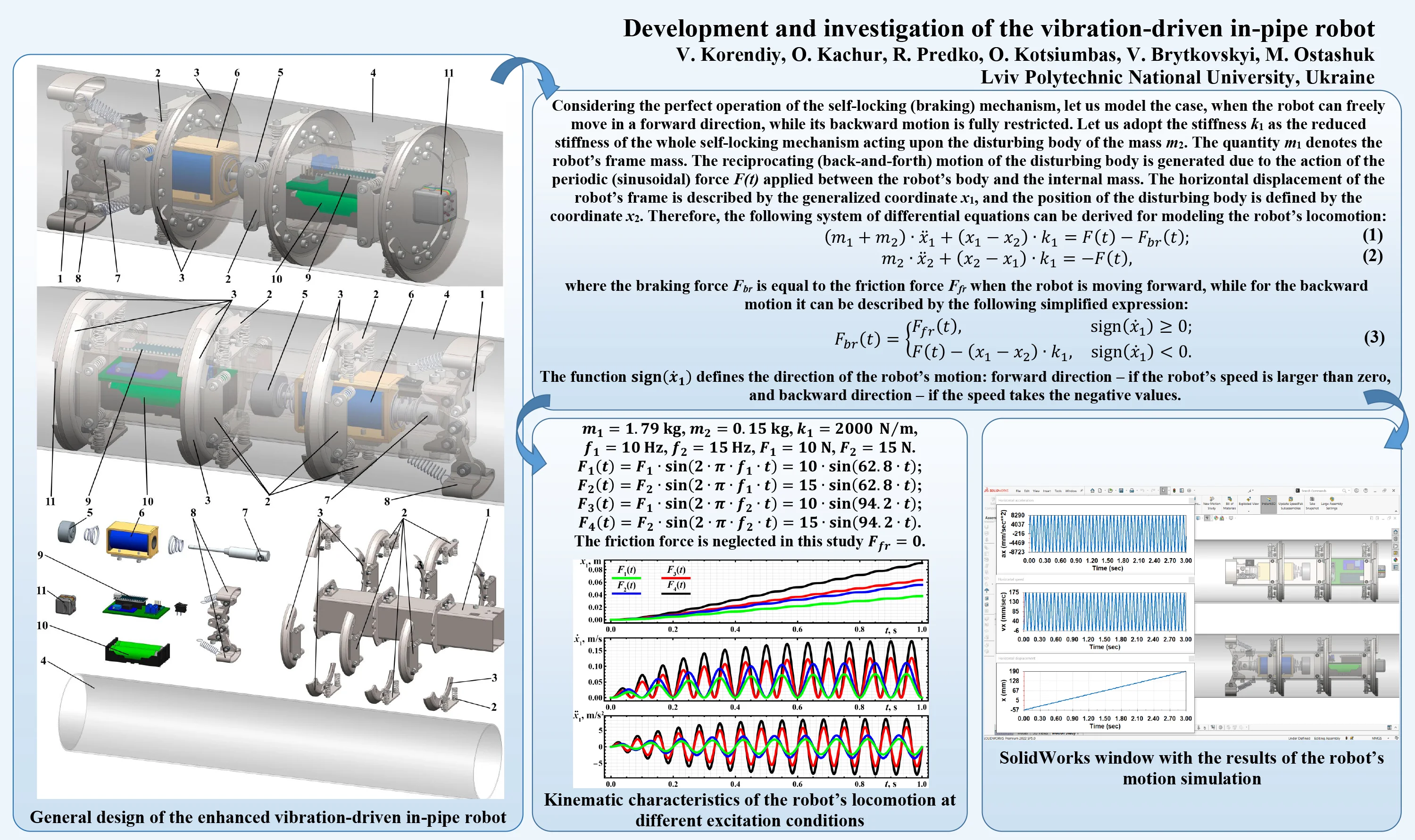
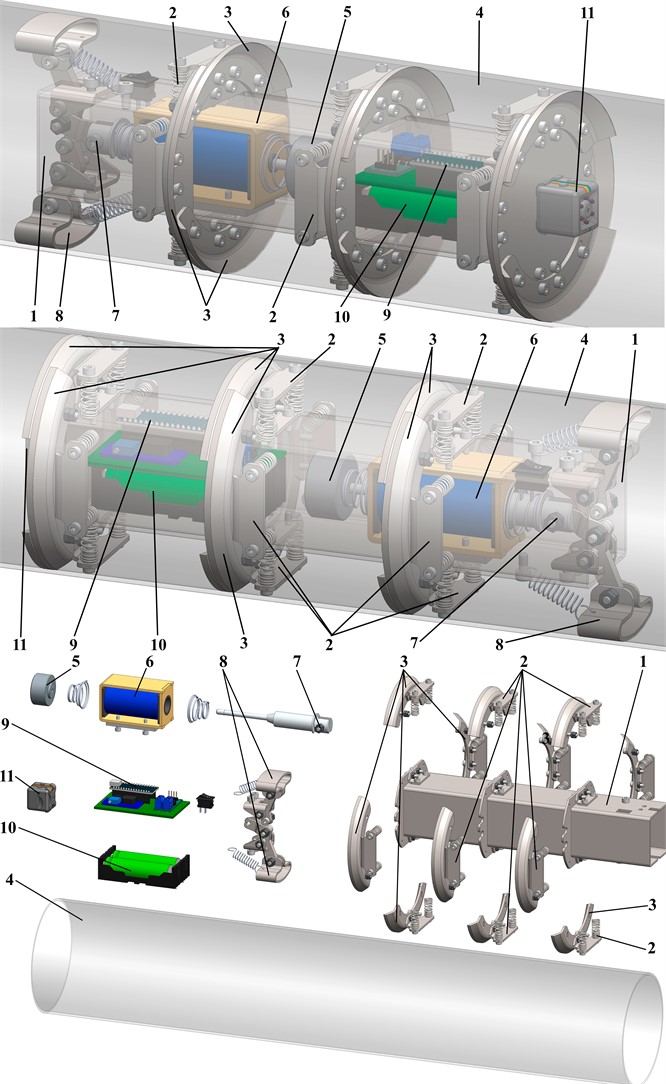
The proposed vibration-driven in-pipe robot consists of the frame (body) 1 made of the square tube, on which all the other components are installed (see Fig. 1). The spring mechanisms 2 are equipped with scrapers (skimmers, badgers) 3 used for supporting the robot’s body 1 and cleaning the internal surfaces of the pipeline 4. The vibrations of the internal (disturbing) body 5 are excited by the solenoid (electromagnet) 6. The rear end of the tappet (pusher, armature, plunger) 7 is hinged to a special lever-type braking mechanism 8 ensuring the self-locking (blocking) characteristics and unidirectional motion of the robot. The control system 9 is based on the Arduino hardware and software and is powered by a set of rechargeable batteries 10. In order to perform the video-inspection of the internal surfaces of the pipeline the robot is working in, the corresponding camera 11 is mounted on the front end of the robot’s body. Therefore, the robot slides inside the pipeline 4 in one direction due to the periodic excitation caused by the reciprocating (back-and-forth) motion of the internal (disturbing) body 5. The self-locking mechanism 8 actuated by the solenoid armature 7 restricts the robot’s backward motion.
Considering the perfect operation of the self-locking (braking) mechanism, let us model the case, when the robot can freely move in a forward direction, while its backward motion is fully restricted. Let us adopt the stiffness as the reduced stiffness of the whole self-locking mechanism acting upon the disturbing body of the mass . The quantity denotes the robot’s frame mass. The reciprocating (back-and-forth) motion of the disturbing body is generated due to the action of the periodic (sinusoidal) force applied between the robot’s body and the internal mass. The horizontal displacement of the robot’s frame is described by the generalized coordinate , and the position of the disturbing body is defined by the coordinate . Therefore, the following system of differential equations can be derived for modeling the robot’s locomotion:
where the braking force is equal to the friction force when the robot is moving forward, while for the backward motion it can be described by the following simplified expression:
The function defines the direction of the robot’s motion: forward direction – if the robot’s speed is larger than zero, and backward direction – if the speed takes the negative values.
Fig. 1General design of the enhanced vibration-driven in-pipe robot
3. Modeling and simulation of the robot locomotion
Let us use the Runge-Kutta methods integrated into the Mathematica software for solving the differential Eqs. (1) and (2) describing the robot’s dynamic behavior. The initial conditions are assumed to be zero: . The robot’s design parameters are defined on the basis of its 3D-model developed in the SolidWorks software (see Fig. 1): the robot’s frame mass is 1.79 kg; the disturbing mass is 0.15 kg; the reduced stiffness of the spring system is approximately 2000 N/m. While carrying out numerical modeling, let us adopt the forced frequencies of 10 Hz, 15 Hz, and the amplitude values of the sinusoidal excitation force of 10 N, 15 N. In such cases, the time dependencies of the excitation force mentioned in (1) and (2) can be presented as follows: ; ; ; . The friction force is neglected in this study . The corresponding modeling results are shown in Fig. 2 and present the time dependencies of the robot’s displacement, speed, and acceleration during its operation under different working regimes (forced frequencies, excitation force amplitude values).
Fig. 2Kinematic characteristics of the robot’s locomotion at different excitation conditions
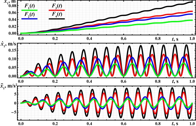
The distance traveled by the robot during the time interval of 1 s at the excitation conditions of , , , correspondingly equals 0.09 m, 0.064 m, 0.056 m, 0.042 m (see Fig. 2). Therefore, its average locomotion speed is approximately 0.09 m/s, 0.064 m/s, 0.056 m/s, 0.042 m/s. The robot’s dynamics is characterized by the periodic stepwise (abrupt) locomotion along the straight horizontal line. The maximal amplitude value of the robot’s speed of about 0.18 m/s is observed at the forced frequency of 15 Hz and the amplitude value of the excitation force of 15 N. The smallest amplitude value of the speed does not exceed 0.08 m/s at the 10 Hz forced frequency and 10 N excitation force amplitude. The horizontal acceleration of the robot’s body reaches the maximal amplitude values of approximately 8.5 m/s2 at the largest excitation conditions and equals about 2 m/s2 at the lowest forced frequency and excitation force.
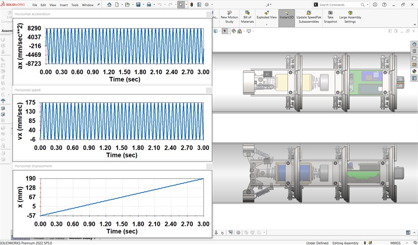
The computer simulation of the robot’s locomotion is carried out in the SolidWorks Motion software at the forced frequency of 15 Hz and amplitude value of the excitation force of 15 N. The corresponding window with the simulation results is presented in Fig. 3. During the simulation time equal to 3 s, the robot’s body changed its position from –57 mm to 190 mm. This means that the robot passed a distance of about 247 mm. In such a case, its average speed is approximately 82 mm/s. Due to the imperfection of the self-locking (blocking, braking) mechanism, the robot’s body periodically moves backward at the maximal speed of 6 mm/s, while the maximal forward speed reaches 175 mm/s. Considering the maximal and minimal acceleration values, they are equal to 8290 mm/s2 and – 8723 mm/s2, respectively. In general, the obtained simulation results (Fig. 4) are in good agreement with the results of theoretical investigations performed in the Mathematica software (see Fig. 2). The robot’s locomotion conditions correspond to the ones previously modeled and experimentally tested in [15] and [16].
Fig. 3SolidWorks window with the results of the robot’s motion simulation
The following stage of the presented above investigations will deal with developing the full-scale laboratory prototype of the proposed vibration-driven in-pipe robot. The experimental studies are aimed at substantiating the real performance parameters and locomotion characteristics of the considered robot, as well as defining its optimal operating conditions providing minimal power consumption and maximal translational speed while performing the inspecting and cleaning of the internal surfaces of pipelines. Some aspects of the locomotion conditions optimization of the electromagnetically-driven robots are considered in [13]. In addition, the experimental investigations will allow us to improve the robot’s control system and choose the appropriate autonomous power supply source. These problems are partially solved in [14] and [17].
4. Conclusions
The paper presents the novel vibration-driven locomotion system intended for inspecting and cleaning the pipelines and equipped with an electromagnetic (solenoid-type) exciter and the spring-lever self-locking (blocking, braking) mechanism. In addition, the proposed robot can perform additional video-monitoring of the pipelines’ internal surfaces. The dynamic behavior and the robot’s locomotion characteristics are studied based on mathematical modeling using the Mathematica software and computer simulation with the help of the SolidWorks software. The investigations are carried out at the forced frequencies of 10 and 15 Hz, and the amplitude values of the excitation force of 10 and 15 N. The modeling and simulation results showed that the maximal value of the robot’s average locomotion speed is in the range of 0.08…0.09 m/s and is reached at the forced frequency of 15 Hz and amplitude value of the excitation force of 15 N.
The obtained results can be implemented in practice while designing new prototypes of the in-pipe robots, developing their control systems, and defining the most efficient working regimes. Further investigations may be focused on creating and testing the experimental prototype of the vibration-driven robot based on the proposed design. The experimental studies must help to substantiate the real performance parameters and locomotion characteristics of the robot, define its optimal operating conditions, improve the control system, and choose the power supply source.
References
-
H. Jang et al., “A review: technological trends and development direction of pipeline robot systems,” Journal of Intelligent and Robotic Systems, Vol. 105, No. 3, pp. 1–20, Jul. 2022, https://doi.org/10.1007/s10846-022-01669-2
-
C. Rusu and M. O. Tatar, “Adapting mechanisms for in-pipe inspection robots: a review,” Applied Sciences, Vol. 12, No. 12, p. 6191, Jun. 2022, https://doi.org/10.3390/app12126191
-
E. Cao, H. Tan, Y. Bian, Z. Guo, and F. Zhou, “Design and realization of a 6-wheeled in-pipe robot,” in Journal of Physics: Conference Series, Vol. 2356, No. 1, p. 012010, Oct. 2022, https://doi.org/10.1088/1742-6596/2356/1/012010
-
V. Korendiy, V. Gursky, O. Kachur, P. Dmyterko, O. Kotsiumbas, and O. Havrylchenko, “Mathematical model and motion analysis of a wheeled vibro-impact locomotion system,” Vibroengineering Procedia, Vol. 41, pp. 77–83, Apr. 2022, https://doi.org/10.21595/vp.2022.22422
-
V. Korendiy et al., “Motion simulation and impact gap verification of a wheeled vibration-driven robot for pipelines inspection,” Vibroengineering Procedia, Vol. 41, pp. 1–6, Apr. 2022, https://doi.org/10.21595/vp.2022.22521
-
A. Kaiwart, N. D. Dubey, F. Naseer, A. Verma, and S. Pradhan, “Design of adaptive wheel driven pipeline inspection robot,” in Lecture Notes in Mechanical Engineering, Singapore: Springer Singapore, 2022, pp. 583–595, https://doi.org/10.1007/978-981-16-9613-8_54
-
S. Kazeminasab and M. K. Banks, “SmartCrawler: a size-adaptable in-pipe wireless robotic system with two-phase motion control algorithm in water distribution systems,” Sensors, Vol. 22, No. 24, p. 9666, Dec. 2022, https://doi.org/10.3390/s22249666
-
M. M. Salvatore, A. Galloro, L. Muzzi, G. Pullano, P. Odry, and G. Carbone, “Design of PEIS: a low-cost pipe inspector robot,” Robotics, Vol. 10, No. 2, p. 74, May 2021, https://doi.org/10.3390/robotics10020074
-
V. Gurskyi, V. Korendiy, P. Krot, R. Zimroz, O. Kachur, and N. Maherus, “On the dynamics of an enhanced coaxial inertial exciter for vibratory machines,” Machines, Vol. 11, No. 1, p. 97, Jan. 2023, https://doi.org/10.3390/machines11010097
-
V. Korendiy and O. Kachur, “Dynamic behavior of a vibratory plate compactor working on a horizontal elastic-viscous-plastic surface,” in Lecture Notes in Mechanical Engineering, pp. 434–443, 2023, https://doi.org/10.1007/978-3-031-16651-8_41
-
Q. Xie, S. Liu, and X. Ma, “Design of a novel inchworm in-pipe robot based on cam-linkage mechanism,” Advances in Mechanical Engineering, Vol. 13, No. 9, p. 168781402110451, Sep. 2021, https://doi.org/10.1177/16878140211045193
-
H. Zhang, M. Gao, Z. Li, and Q. Wu, “Vibration analysis of an in-pipe inspection robot considering fluid-structure coupling,” International Journal of Structural Stability and Dynamics, Vol. 22, No. 5, pp. 1–30, Apr. 2022, https://doi.org/10.1142/s0219455422500559
-
L. Xiao, R. R. Sattarov, Y. Zhu, and X. Huang, “Optimal sliding mode control of electromagnetic worm-like locomotion systems for in-pipe robots,” International Journal of Dynamics and Control, Vol. 11, No. 1, pp. 324–337, Feb. 2023, https://doi.org/10.1007/s40435-022-00972-y
-
Y. Oka, A. Kakogawa, Y. Tian, and S. Ma, “Control technique of a V-shaped in-pipe robot composed of two underactuated roll-pitch joints,” Advanced Robotics, Vol. 36, No. 4, pp. 205–216, Feb. 2022, https://doi.org/10.1080/01691864.2021.2012513
-
V. Korendiy, O. Kotsiumbas, V. Borovets, V. Gurey, and R. Predko, “Mathematical modeling and computer simulation of the wheeled vibration-driven in-pipe robot motion,” Vibroengineering Procedia, Vol. 44, pp. 1–7, Aug. 2022, https://doi.org/10.21595/vp.2022.22832
-
V. Korendiy, O. Kachur, V. Gurskyi, and P. Krot, “Studying the influence of the impact gap value on the average translational speed of the wheeled vibration-driven robot,” Engineering Proceedings, Vol. 24, No. 1, p. 25, Sep. 2022, https://doi.org/10.3390/iecma2022-12897
-
V. Korendiy, O. Kachur, and R. Predko, “Development of a remote-control system for a mobile vibration-driven robot,” in 2023 17th International Conference on the Experience of Designing and Application of CAD Systems (CADSM), pp. 6–10, Feb. 2023, https://doi.org/10.1109/cadsm58174.2023.10076517
Cited by
About this article

The authors have not disclosed any funding.
The datasets generated during and/or analyzed during the current study are available from the corresponding author on reasonable request.
The authors declare that they have no conflict of interest.
