Abstract
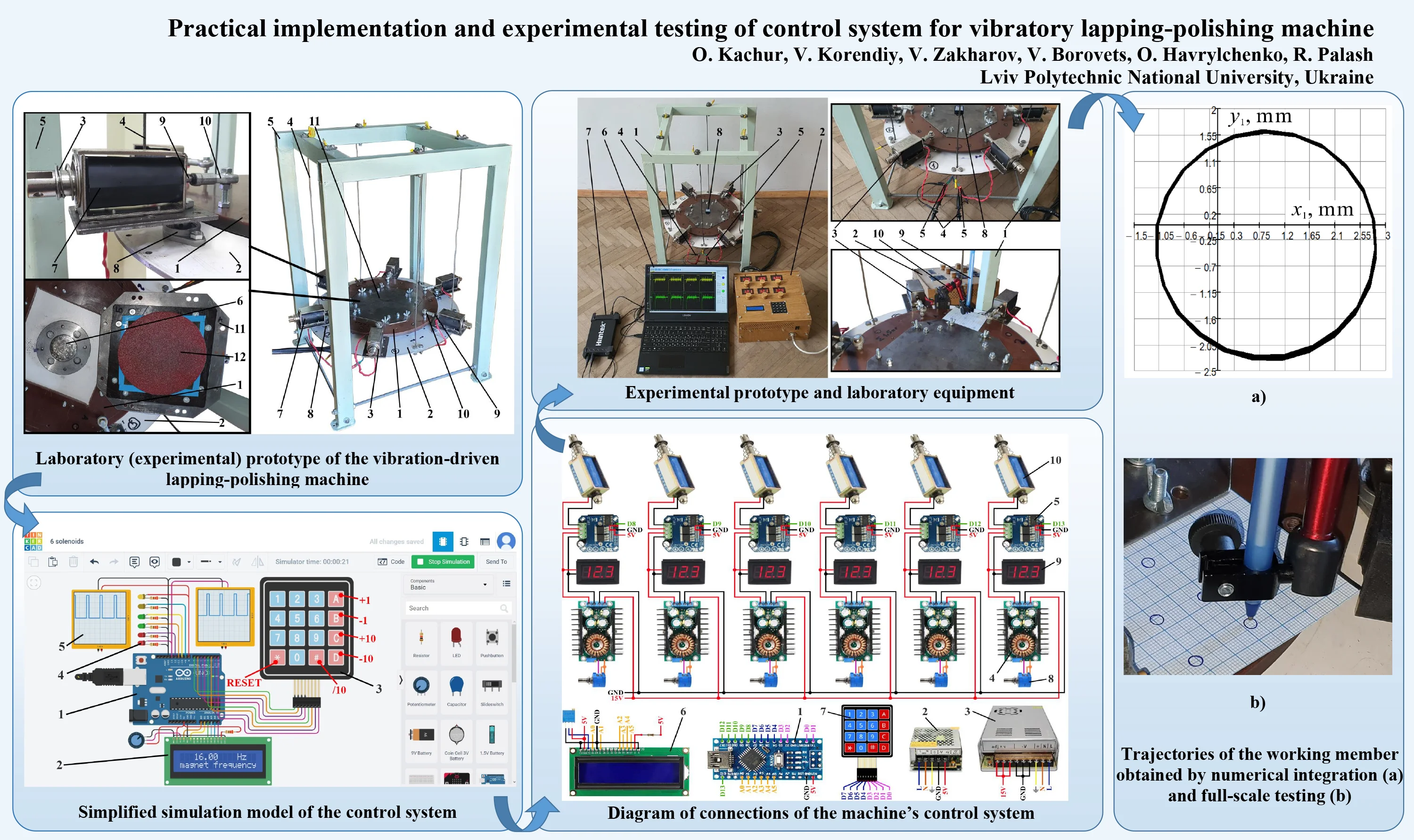
Vibratory technological machines are widely implemented in various branches of industrial, manufacturing, and mechanical engineering. Particularly, such equipment can be effectively used while conducting finishing technological operations, e.g., lapping and polishing of different machine parts. The present paper is focused on developing the control system for the novel design of a vibratory lapping-polishing machine driven by six solenoids. The main purpose consists in providing the circular trajectory of the working member and ensuring the machining uniformity at each point of the surface being treated. In such a case, it is proposed to actuate the solenoids with the specified time shift depending on the forced frequency needed to be provided. The duration of the signal actuating the solenoid is equal to one-sixth of the total duration of a cycle (period) of the working body oscillation. The corresponding control approach is developed and simulated in the Tinkercad application, while the control system is designed based on the Arduino software and hardware. In addition, the laboratory prototype of the vibratory lapping-polishing machine and the corresponding control system are implemented in practice. The performed experimental investigations substantiate the possibilities of generating the circular oscillations of the working member of the vibratory lapping-polishing machine. The obtained results may be useful for engineers and technologists dealing with control systems of various vibratory technological equipment based on electromagnetic and solenoid-type drives.
Highlights
- There is substantiated the possibility of the control system to generate sequential signals when the solenoids are activated with the specified time shift depending on the required forced frequency.
- The proposed control system allows for efficient regulation of the machine’s operational parameters (working member trajectory and speed) depending on the prescribed technological requirements.
- The proposed control system allows for generating the circular oscillations of the working member (lap, polisher, etc.) ensuring the machining uniformity at each point of the surface being treated.
1. Introduction
A wide range of various treatment, processing, and machining operations are used to provide the necessary chemical, mechanical, physical, and technological properties of different materials and parts [1]. Among numerous technological processes (machining, conveying, compacting, etc.), the ones implementing active vibrations of the working members are of the most widespread and efficient [2]. Even the high-tech aviation industry, which requires the improved reliability and accuracy of the corresponding parts and components, usually uses vibratory lapping and polishing operations while performing finishing treatment [3]. Numerous scientific papers are dedicated to investigating the operational peculiarities of various vibratory technological equipment. In particular, the paper [4] considers the simplified models of vibratory finishing machines; in [5] the authors presented the novel approaches of vibratory strengthening the drill and casing pipes; the operations of volumetric vibration treatment of the metal parts placed in rotary devices filled with a special abrasive working medium are studied in [6]. The paper [7] analyzes similar vibration processing of different parts with the help of abrasive liquefied and granulated media. In [8], the authors investigated the peculiarities of implementing the vibratory polishing processes for improving the residual stresses of hard coatings.
In most cases, the lapping operations are conducted using planetary-type mechanisms that simultaneously rotate the parts being treated around two parallel axes. The problems of performing the double-sided lapping of the pure copper parts made in the form of thin substrates are considered in [9]. The paper [10] is dedicated to studying the surface quality of parts that are subject to double-sided planetary-type lapping. In order to ensure sufficient surface quality and treatment accuracy, various techniques are used for dressing the working members (laps, polishers, etc.) [11]. The novel approaches of predicting and monitoring the surface profile during the lapping process are considered in [12], while the possibilities of improving the surface quality by enhancing the lapping machine design are presented in [13].
Numerous other publications deal with planetary-type finishing equipment and technologies, however, the possibilities of implementing the vibration-driven mechanisms for conducting the finishing operations are currently of significant interest among scientists, engineers, and technologists. The present research continues the authors’ previous investigations [14]-[17] dedicated to the development and implementation of vibratory finishing equipment. This paper is focused on developing a special control system for the solenoid-type actuators of the vibratory lapping-polishing machine and providing a circular trajectory of the working member in order to ensure the machining (lapping, polishing) uniformity at each point of the surface being treated.
2. Research methodology
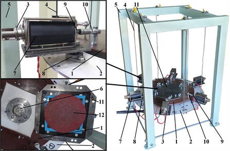
The laboratory (experimental) prototype of the vibration-driven lapping-polishing machine is presented in Fig. 1. The main working members are the upper lap (polisher) 1 and lower carrier 2, in which the metal cylindrical parts are fixed. The oscillations of the upper lap 1 relative to the lower carrier 2 are excited by the system of electromagnets (solenoids) that are uniformly mounted on the lower carrier in a circle. The carrier is suspended by the system of ropes 4 from the machine’s frame (body) 5. The ropes hold the whole oscillatory system and allow its translational motion in a horizontal plane. The parts 6 being treated are fixed on the upper surface of the carrier and are subject to the continuous wear action of the lower processing surface 12 of the plate 11 during the machine operation. The solenoid-type (electromagnetic) exciter consists of the body 7 (with the coil) that is mounted on the plate able to rotate due to the application of the special bearing unit 8. The solenoid rod (armature, pusher) 9 is joined with the upper lap using the spherical hinge 10, and its motion is restricted by the spring 3. The main purpose of the control system to be developed is to provide the circular trajectory of the working member and ensure the machining uniformity at each point of the surface being treated.
Fig. 1Laboratory (experimental) prototype of the vibration-driven lapping-polishing machine
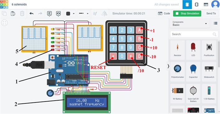
Let us first develop the simplified simulation model of the control system in the Tinkercad software (see Fig. 2). The control system consists of the Arduino UNO board 1, liquid crystal display (LCD) 2, keypad 3, light-emitting diodes (LEDs) 4, and oscilloscopes 5. The LEDs are used to simulate the operation of the solenoids (electromagnets). In order to reduce the sizes of the designed scheme, let us use only two oscilloscopes to define the signals sent to two sequential LEDs. The keypad is programmed to provide the possibility of manually setting the necessary forced frequency from the range of 0.01 Hz to 99.99 Hz that is displayed on the LCD. In order to simplify the setting-up technique, the additional keys are programmed to increase or decrease the forced frequency by 1 Hz or 10 Hz, as well as to divide the present frequency by 10. To stop the machine at any time moment, the RESET button is used. The LCD brightness can be regulated by the potentiometer. The Arduino board is powered by a USB switch.
The simulation results shown on the oscilloscopes (see Fig. 2) substantiate the possibility of generating sequential signals when the LEDs are activated with the specified time shift depending on the forced frequency needed to be provided. In the considered case, the forced frequency is 16 Hz. The duration of the signal activating each LED is equal to one-sixth of the total duration of the whole cycle (period) and can be determined as 1/(16·6) s or approximately 0.01 s. Therefore, by sequential activation of six LEDs (one after another) during the time period of 0.01 s it is possible to generate the oscillations at the forced frequency of 16 Hz. The control program reads the information (the technologically prescribed (necessary) frequency) set by the keypad and regulates the corresponding durations of the signal activating each sequential LED.
Fig. 2Simplified simulation model of the control system
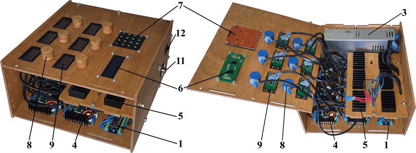
The control system is based on the Arduino software and hardware (see Figs. 3 and 4). Its main component is Arduino Nano board 1. The AC/DC adaptor 2 is used to power the Arduino board 1. Another AC/DC adaptor 3 supplies the 15 V voltage to the DC/DC adjustable step-down converters 4 regulated by the potentiometers 8. The converters 4 allow for manual regulation of the voltage supplied to the drivers 5 of the electromagnets 10 within the range of 1.2…15 V using the potentiometers 8. The electromagnets’ drivers BTS7960 (position 5) are controlled by the Arduino Nano board using the 3.3…5 V signals. The voltages supplied to the drivers are registered by the digital voltmeters 9. The double-pole (on/off) switch KCD1-4-201N (position 12 in Fig. 4) is used to start the system or turn it off. The additional circular connectors GX25F and GX16F (positions 10 and 11 in Fig. 4) are used to connect the control system with the electromagnets and AC power supply network. For exciting the oscillations, the electromagnets (double-acting (push-pull) solenoids ZUIDID KK-1564B) are used. They are characterized by the maximal consumed voltage of 12 V, nominal traction force of 65 N, and the rods’ traveling distance (maximal displacement) of 20 mm. The converters 4 and potentiometers 8 change the voltage magnitude supplied to the electromagnets 10, while the control signals sent by the Arduino board 1 define the forced frequency of the electromagnetic excitation.
The duration of the signal activating each electromagnet is equal to one-sixth of the total duration of the whole cycle (period) and can be determined as 1/(·6) s, where is the technologically required forced frequency. The control program reads this information (prescribed frequency), which is set by the machine operator with the help of the membrane-type keypad 9 and shown on the LCD QC1602A display 6. Therefore, by sequential activation of six electromagnets (one after another) during the time period of 1/(·6) s it is possible to generate circular oscillations of the machine’s working member (lap, polisher, etc.). The diameters of the circles can be controlled by adjusting the voltage supplied to the drivers and electromagnets.
Fig. 3Diagram of connections of the machine’s control system
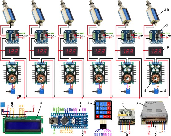
Fig. 4Breadboard model of the machine’s control system
3. Results and discussion
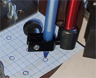
The experimental prototype of the lapping-polishing machine and the corresponding laboratory equipment are presented in Fig. 5. The machine 1 is mounted on the unmovable base. The control system box 2 is powered from the AC supply network and is connected with the electromagnets (solenoids) 3. The probes 4 and 5 of the oscilloscope 7 (Hantek 6022BE) are connected with the wires, which supply power to two sequential solenoids (acting one after another). The oscilloscope 7 is also connected to the laptop 6 using the USB interface. The Hantek software is installed on the laptop to register the measurements, which represent voltage signals supplied to each of the two sequential electromagnets. To determine the kinematic parameters of the working member motion (acceleration, speed, displacement) in two axes of the horizontal plane (working surface), the accelerometer 8 (WitMotion BWT901CL) is fixed on the upper lap (polisher). The accelerometer is connected to the laptop using the Bluetooth interface, and the corresponding WitMotion software is used to register the acceleration of the working member. The experimental data is subjected to further analysis and numerical integration in the MathCad software to receive the speeds and displacements of the working member. The holder 10 and pen 9 are mounted on the lower carrier for drawing the trajectory of the upper lap.
The machine’s control system is tested at the forced frequencies of 4.33 Hz and supplied voltage of 12 V. The corresponding results are presented in Fig. 6. The plot shows that the signals activating the first and the second solenoids have a duration of about 0.04 s each. The end time moment of the first signal (yellow curve) coincides with the start time of the second signal (green curve). The measured signal duration allows for determining the total period of one cycle. Considering the operation of six solenoids, the period is equal to 0.24 s and, hence, the forced frequency is approximately 4.17 Hz which almost corresponds to the initially prescribed value. The signal step-down at the end of the solenoid activation can be explained by its self-induction. All the other signal jumps can be considered as impulse and modulation noises.
Fig. 5Experimental prototype and laboratory equipment
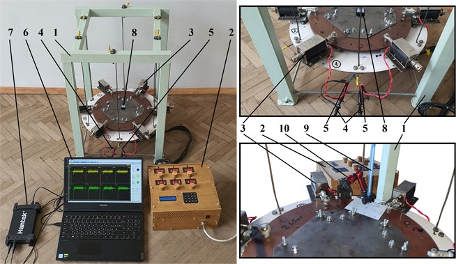
Fig. 6Results of testing the control system
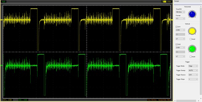
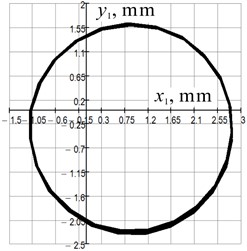
Fig. 7a) Trajectories of the working member obtained by numerical integration and b) full-scale testing
a)
b)
The last stage of the research is dedicated to full-scale testing of the machine operation under the action of the developed control system. The experimental measurements (lap accelerations) are registered by the WitMotion sensor and sent to the corresponding software installed on the laptop. The obtained data is numerically integrated in the MathCad software which allows for defining the time dependencies of the working member speed and displacement along two mutually perpendicular axes of the horizontal plane (working surface). The numerically obtained plot describing the trajectory of the working member motion during the machine operation at the forced frequencies 4.33 Hz and supplied voltage of 12 V are shown in Fig. 7(a). The real-time paths of the working member drawn by a pen mounted in a fixed holder are presented in Fig. 7(b). The diameter of the lap’s (polisher’s) circular trajectory is approximately equal to 4 mm for both “numerical integration” and “pen-drawing” experimental techniques.
4. Conclusions
The research is focused on the development, computer simulation, and experimental testing of the control system of the vibratory lapping-polishing machine (Fig. 4). The simulation results (Fig. 2) substantiate the possibility of the control system to generate sequential signals when the solenoids are activated with the specified time shift depending on the forced frequency needed to be provided. The results of experiments (Fig. 7) proved that the proposed control system allows for efficient regulation of the machine’s operational parameters depending on the prescribed technological requirements and provides the circular oscillations of the working member (lap, polisher, etc.) ensuring the machining uniformity at each point of the surface being treated. The results of the carried-out investigations may be used by engineers and technologists dealing with control systems of various vibratory technological equipment based on electromagnetic and solenoid-type drives while adjusting the operational conditions and improving the performance.
References
-
Y. Kharchenko et al., “Nanostructural changes in a Ni/NiO cermet during high-temperature reduction and reoxidation,” Springer Proceedings in Physics, Vol. 246, pp. 219–229, 2021, https://doi.org/10.1007/978-3-030-51905-6_17
-
V. Gurskyi, V. Korendiy, P. Krot, R. Zimroz, O. Kachur, and N. Maherus, “On the dynamics of an enhanced coaxial inertial exciter for vibratory machines,” Machines, Vol. 11, No. 1, p. 97, Jan. 2023, https://doi.org/10.3390/machines11010097
-
R. Mediratta, K. Ahluwalia, and S. H. Yeo, “State-of-the-art on vibratory finishing in the aviation industry: an industrial and academic perspective,” The International Journal of Advanced Manufacturing Technology, Vol. 85, No. 1-4, pp. 415–429, Jul. 2016, https://doi.org/10.1007/s00170-015-7942-0
-
F. Hashimoto and S. P. Johnson, “Modeling of vibratory finishing machines,” CIRP Annals, Vol. 64, No. 1, pp. 345–348, 2015, https://doi.org/10.1016/j.cirp.2015.04.004
-
I. S. Aftanaziv, L. I. Shevchuk, L. R. Strutynska, and O. I. Strogan, “Vibrational-centrifugal surface strengthening of drill and casing pipes,” Naukovyi Visnyk Natsionalnoho Hirnychoho Universytetu, No. 5, pp. 88–97, 2018, https://doi.org/10.29202/nvngu/2018-5/7
-
V. Borovets, O. Lanets, V. Korendiy, and P. Dmyterko, “Volumetric vibration treatment of machine parts fixed in rotary devices,” in Lecture Notes in Mechanical Engineering, pp. 373–383, 2021, https://doi.org/10.1007/978-3-030-68014-5_37
-
J. Kundrák, M. Morgan, A. V. Mitsyk, V. A. Fedorovich, and A. I. Grabchenko, “Mathematical simulation of the vibration treatment of parts in a liquefied abrasive working medium,” The International Journal of Advanced Manufacturing Technology, Vol. 120, No. 7-8, pp. 5377–5398, Jun. 2022, https://doi.org/10.1007/s00170-022-08843-8
-
C. Micallef, K. Walton, Y. Zhuk, and A. I. Aria, “Surface finishing and residual stress improvement of chemical vapour deposited tungsten carbide hard coatings by vibratory polishing,” Surface and Coatings Technology, Vol. 439, p. 128447, Jun. 2022, https://doi.org/10.1016/j.surfcoat.2022.128447
-
J. Guo et al., “Stress-induced deformation of thin copper substrate in double-sided lapping,” Chinese Journal of Mechanical Engineering, Vol. 36, No. 1, pp. 1–10, Feb. 2023, https://doi.org/10.1186/s10033-022-00824-y
-
L. Yang, X. Guo, R. Kang, X. Zhu, and Y. Jia, “Effect of kinematic parameters considering workpiece rotation on surface quality in YAG double-sided planetary lapping with the trajectory method,” The International Journal of Advanced Manufacturing Technology, Vol. 123, No. 7-8, pp. 2679–2690, Dec. 2022, https://doi.org/10.1007/s00170-022-10288-y
-
L. Zhao et al., “A real-time dressing method for metal lapping pads based on the thermal deformation effect,” The International Journal of Advanced Manufacturing Technology, Vol. 120, No. 1-2, pp. 945–958, May 2022, https://doi.org/10.1007/s00170-022-08869-y
-
Z. Geng, P. Zhou, L. Meng, Y. Yan, and D. Guo, “Prediction of surface profile evolution of workpiece and lapping plate in lapping process,” Journal of Manufacturing Science and Engineering, Vol. 144, No. 8, p. 08100, Aug. 2022, https://doi.org/10.1115/1.4053279
-
Z. Chen, D. Wen, J. Lu, J. Yang, and H. Qi, “Surface quality improvement by using a novel driving system design in single-side planetary abrasive lapping,” Materials, Vol. 14, No. 7, p. 1691, Mar. 2021, https://doi.org/10.3390/ma14071691
-
V. Korendiy, V. Zakharov, V. Gurey, P. Dmyterko, I. Novitskyi, and O. Havrylchenko, “Modelling the operation of vibratory machine for single-sided lapping of flat surfaces,” Vibroengineering Procedia, Vol. 38, pp. 1–6, Jun. 2021, https://doi.org/10.21595/vp.2021.22001
-
V. Korendiy, O. Kachur, V. Zakharov, I. Kuzio, O. Havrylchenko, and T. Hurey, “Dynamics and control of vibratory finishing machine with translational motion of lapping-polishing plates,” Vibroengineering Procedia, Vol. 44, pp. 8–14, Aug. 2022, https://doi.org/10.21595/vp.2022.22842
-
V. Korendiy, O. Kachur, V. Zakharov, and I. Kuzio, “Studying the dynamics of a vibratory finishing machine providing the single-sided lapping and polishing of flat surfaces,” Engineering Proceedings, Vol. 24, No. 1, p. 9, Sep. 2022, https://doi.org/10.3390/iecma2022-12898
-
V. Korendiy, O. Kachur, V. Zakharov, I. Kuzio, I. Hurey, and R. Predko, “Experimental study of the lap motion trajectory of vibratory finishing machine,” Vibroengineering Procedia, Vol. 46, pp. 1–7, Nov. 2022, https://doi.org/10.21595/vp.2022.23002
About this article

The authors have not disclosed any funding.
The datasets generated during and/or analyzed during the current study are available from the corresponding author on reasonable request.
The authors declare that they have no conflict of interest.
