Abstract
Vibratory equipment is widely used for performing various finishing processes, machining and forcing of different parts and materials. Numerous researchers and technologists pay specific attention to the possibilities of implementing vibration-driven machinery for conducting the lapping and polishing operations on flat surfaces. The present paper is dedicated to studying the laps kinematic parameters of the vibratory finishing machine actuated by six electromagnets. The paper’s scientific novelty consists in the experimental verification of the previously modelled and simulated circular trajectories of the laps under different operational conditions. The methodology of research contains two basic stages: changing the excitation frequency at the constant traction force and changing the traction force at the constant excitation frequency. The improved 3D-design of the vibratory finishing machine was developed in the SolidWorks software. The experimental prototype was implemented in practice, and full-scale tests were carried out using the WitMotion sensors and software. Based on the obtained experimental data, the trajectories of the machine’s laps were constructed and analyzed in the MathCad software. The research results substantiate the possibilities of providing circular oscillations of the laps at different operational conditions. The results can be used by technologists and engineers while choosing the appropriate design and control parameters for similar vibratory equipment intended for lapping and polishing of flat surfaces.
Highlights
- The enhanced design and experimental prototype of a vibratory finishing machine, used for lapping-polishing of flat surfaces and actuated by six electromagnets installed in a circle, are developed.
- Experimental investigations on the kinematic characteristics of the machine's working element (lap, polisher) are conducted at Vibroengineering Laboratory of Lviv Polytechnic National University.
- The obtained results allow for substantiating the possibilities of generating circular trajectories of a working element, which provide the improved efficiency and accuracy of the lapping process.
1. Introduction
Finishing treatment is one of the most important technological operations. It can be performed by numerous methods and with the help of various technological equipment. Specific attention is currently paid to the vibratory treatment [1]-[6], which can be implemented while conducting grinding, lapping, polishing, strengthening, hardening, compacting, drying, cooling, cleaning, stress relieving, cutting, and other operations. The characteristic feature of vibratory finishing equipment consists in utilizing the vibrations excited by a certain type of actuator for performing various treatment and processing tasks.
Among a large number of finishing operations, the lapping and polishing ones are the most commonly used [7]-[12]. For example, the problems of practical implementation of the double-sided polishing processes are thoroughly studied in [7]. The paper [8] considers the double-sided lapping processes performed with the help of the fixed diamond abrasive pad. In [9], the authors investigated the influence of the carriers’ planetary motion parameters on the efficiency of the double-sided lapping of cylindrical surfaces of the bearing rollers. The model describing the wear processes affecting the lapping plates while implementing the planarization technologies is developed in [10]. The paper [11] defines the relationships between the lapping conditions and technological parameters of the surface being treated. In [12], the authors proposed a novel design of the planetary-type mechanism for conducting a single-sided lapping process.
The present research continues the authors’ previous investigations published in [13]-[15]. The main idea of the improved design of the vibratory lapping-polishing machine consists in providing the circular oscillatory motion of the upper lap relative to the parts being treated. This allows for ensuring the uniformity of the relative velocities of any point of the lapping plate and improving the efficiency and accuracy of the lapping process. This paper is focused on the first stage of investigations dealing with the kinematic parameters of the lap, while further studies will be dedicated to substituting its technological efficiency.
2. Research methodology
2.1. 3D-design and experimental prototype of vibratory lapping machine
The initial design of the vibratory lapping machine (Fig. 1(a, b)) has been proposed in [14]. The corresponding experimental prototype (Fig. 1(c, d)) has been manufactured in the Vibroengineering Laboratory of Lviv Polytechnic National University.
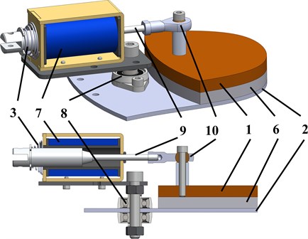
Fig. 13D-model and experimental prototype of the vibratory lapping machine
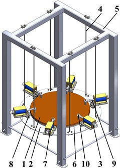
a) General design
b) Scheme of the electromagnets installation
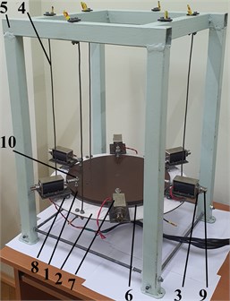
c) Experimental prototype
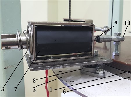
d) Electromagnetic exciter
The vibratory lapping machine (Fig. 1) consists of the upper lap 1 whose bottom surface acts upon the parts’ upper surfaces being treated (polished, lapped). The parts are fixed in the carrier 6 connected to the lower plate 2. The latter is suspended by the ropes 4 from the machine’s frame (body) 5. The actuating electromagnets (linear solenoids) 7 are installed on the lower plate 2 with the help of the bearing units 8. The latter allow electromagnets 7 to rotate in the horizontal plane. The retractable rods 9 of the electromagnets 7 are constrained by the springs 3 and are connected to the upper lap by the plain bearings 10. The electromagnets set the upper and the lower plate into the oscillatory motion. By applying the specific phase shifts and magnitudes of the voltage signals supplied to the electromagnets, it is expected to obtain the circular oscillatory motion of the upper lap relative to the parts being treated.
2.2. Experimental technique and equipment
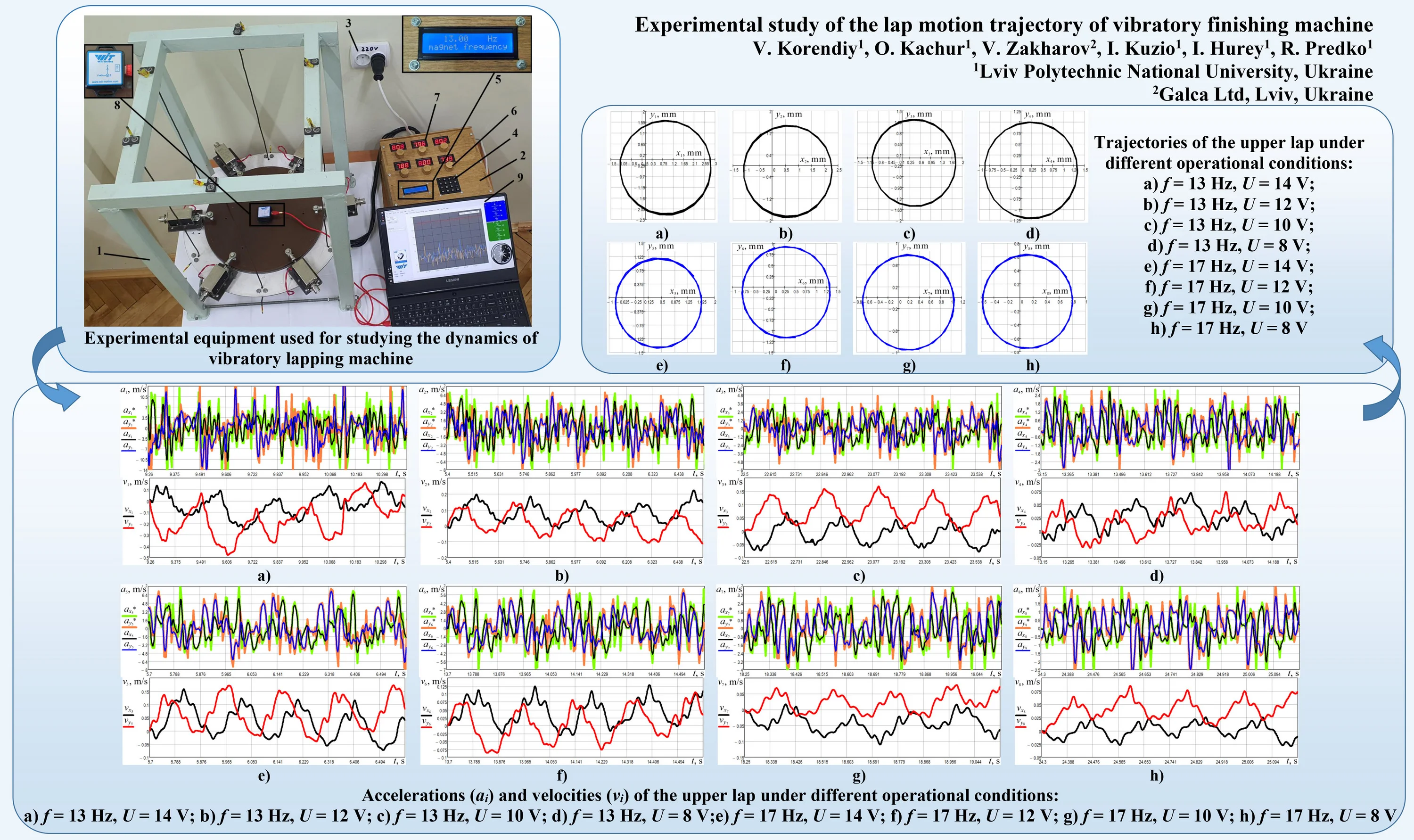
The electromagnets (linear solenoids) of the vibratory lapping machine 1 are powered by the supply unit 2, which is plugged in at the socket 3 of the single-phase alternating current. The supplied voltage is 220 V. The power unit 2, based on the pulse-duration (pulse-width) modulators, transforms the sinusoidal voltage signal into the rectangular one characterized by the controllable voltage whose value manually changes from 0 to 12 V and frequency – in the range of 0…50 Hz. The control system allows for setting the necessary frequency using the keyboard 4, and the corresponding value is shown on the screen 5. The regulation of the voltage magnitude is manually performed with the help of the potentiometers (adjustable resistors) 6, and the corresponding voltmeters 7 show the voltage value supplied to a particular electromagnet. In order to study the kinematic characteristics of the vibratory finishing machine, the WitMotion accelerometer 8 is fixed on the upper lap. The experimental data is sent from the accelerometer to the laptop 9 with the installed WitMotion software.
The retrieval rate of the accelerometer is equal to 200 Hz. This allows for measuring two components of the upper lap horizontal acceleration every 0.005 s. The registered data is interpolated using the built-in functions in the MathCad software. Then, the processed (interpolated) time dependencies of accelerations are numerically integrated with respect to time, and the plots of the lap speeds and displacements are obtained. Using the time dependencies of the lap displacements along two horizontal axes, the corresponding trajectories are plotted, and the possibilities of generating circular oscillations of the upper lap are considered.
Fig. 2Experimental equipment used for studying the dynamics of vibratory lapping machine
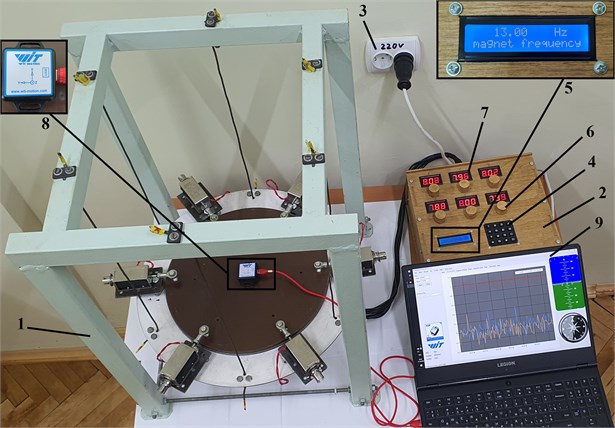
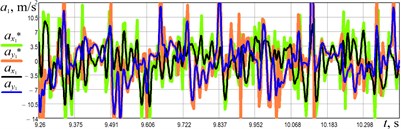
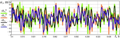
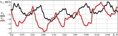
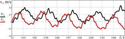
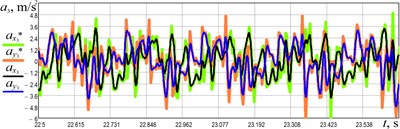
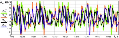
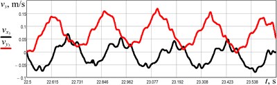
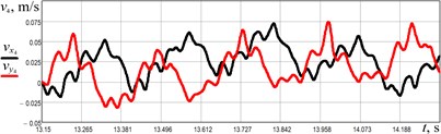
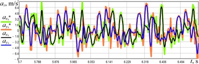
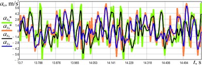
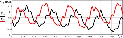
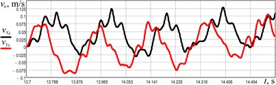
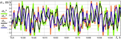
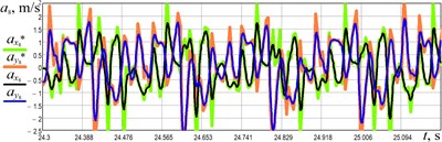
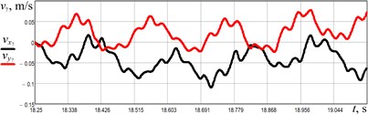
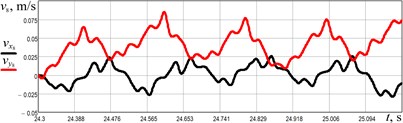
Fig. 3Accelerations (ai) and velocities (vi) of the upper lap under different operational conditions: a) f= 13 Hz, U= 14 V; b) f= 13 Hz, U= 12 V; c) f= 13 Hz, U= 10 V; d) f= 13 Hz, U= 8 V; e) f= 17 Hz, U= 14 V; f) f= 17 Hz, U= 12 V; g) f= 17 Hz, U= 10 V; h) f= 17 Hz, U= 8 V
a)
b)
c)
d)
e)
f)
g)
h)
3. Results and discussion
The experimental investigations were carried out at different values of the forced frequency and supplied voltage . The obtained results are presented in Fig. 3.
The obtained experimental data allows for concluding that the largest accelerations of the upper lap of over 10 m/s2 take place at the supplied voltage of 14 V (Fig. 3(a, e)). In these cases, the lap maximal speeds are in the range of 0.1…0.2 m/s. The smallest accelerations of about 3 m/s2 are observed at the supplied voltage of 8 V (Fig. 3(d, h)). Herewith, the minimal speeds do not exceed 0.08 m/s. Comparing the experimental results obtained at the same supplied voltage and at different forced frequencies, it can be concluded that the increase in the forced frequency causes a decrease in the lap acceleration and speed. In turn, this will cause a decrease in the lap displacement.
In particular, considering Fig. 3(b) and 3(f), the maximal acceleration and speed reach approximately 8 m/s2 and 0.22 m/s at the forced frequency of 13 Hz, whilst the maximal values for the frequency of 17 Hz do not exceed 7 m/s2 and 0.13 m/s, respectively. Similar conclusions can be made at other supplied voltages. In general, the lap motion is characterized by strict periodicity (repetition) and spacing at all the considered operational conditions.
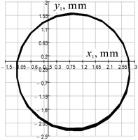
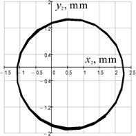
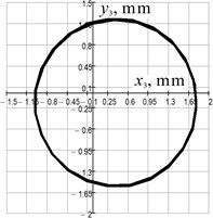
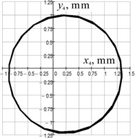
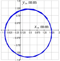
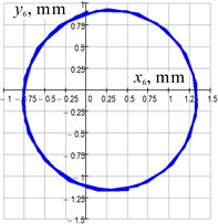
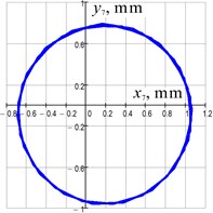
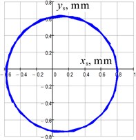
The lats stage of this research is focused on analyzing the lap trajectories. Using the time dependencies of the lap velocities under different operational conditions, the corresponding displacements have been obtained by numerical integration in the MathCad software. This allows for plotting the plane curves describing the lap trajectories (Fig. 4). Analyzing the obtained results, it can be concluded that the lap performs circular oscillations under different operational conditions when all the magnets are powered by the voltage of the same magnitude and frequency. Herewith, it is necessary to mention that the phase shift of the voltage supply to the neighbouring electromagnets is equal to /6 (60°). The larger amplitudes of the lap oscillations are observed at the larger supplied voltages. For example, at the forced frequency of 13 Hz, the maximal radius of the lap circular trajectory is about 2 mm at the voltage of 14 V, whilst the minimal radius of 1.1 mm is observed at 8 V (see Fig. 4(a, d)). Considering the case of the same supplied voltage and different forced frequencies, it can be concluded that the increase in the forced frequency causes a decrease in the lap amplitude. For example, at the voltage of 14 V, the radius of the lap circular trajectory is about 2 mm at the forced frequency of 13 Hz, whilst the radius of approximately 1.2 mm is observed at 17 Hz (see Fig. 4(a, d)).
Fig. 4Trajectories of the upper lap under different operational conditions: a) f= 13 Hz, U= 14 V; b) f= 13 Hz, U= 12 V; c) f= 13 Hz, U= 10 V; d) f= 13 Hz, U= 8 V; e) f= 17 Hz, U= 14 V; f) f= 17 Hz, U= 12 V; g) f= 17 Hz, U= 10 V; h) f= 17 Hz, U= 8 V
a)
b)
c)
d)
e)
f)
g)
h)
4. Conclusions
The paper is dedicated to the experimental study of the kinematic characteristics of the novel vibratory finishing machine actuated by six electromagnets (linear solenoids). The machine has been designed and implemented in practice in the Vibroengineering Labotarory of Lviv Polytechnic National University. The experimental tests were performed at different forced frequencies (13 and 17 Hz) and supplied voltages (8, 10, 12, 14 V). Ensuring the phase shift of the voltage supply to the neighbouring electromagnets equal to /6 (60°), the possibilities of providing circular oscillations of the lap were substantiated at different operational conditions. The largest accelerations, speeds, and displacements of the upper lap of over 10 m/s2, 0.2 m/s, and 2 mm, respectively, take place at the supplied voltage of 14 V and forced frequency of 13 Hz. The obtained results and drawn conclusions can be used by technologists and engineers while choosing the appropriate design and control parameters for similar vibratory equipment intended for lapping and polishing of flat surfaces.
References
-
D. A. Davidson, “Vibratory finishing: Versatile, effective, and reliable,” Metal Finishing, Vol. 106, No. 5, pp. 30–34, May 2008, https://doi.org/10.1016/s0026-0576(08)80123-7
-
F. Hashimoto and S. P. Johnson, “Modeling of vibratory finishing machines,” CIRP Annals, Vol. 64, No. 1, pp. 345–348, 2015, https://doi.org/10.1016/j.cirp.2015.04.004
-
R. Mediratta, K. Ahluwalia, and S. H. Yeo, “State-of-the-art on vibratory finishing in the aviation industry: an industrial and academic perspective,” The International Journal of Advanced Manufacturing Technology, Vol. 85, No. 1-4, pp. 415–429, Jul. 2016, https://doi.org/10.1007/s00170-015-7942-0
-
V. Borovets, O. Lanets, V. Korendiy, and P. Dmyterko, “Volumetric vibration treatment of machine parts fixed in rotary devices,” in Lecture Notes in Mechanical Engineering, pp. 373–383, 2021, https://doi.org/10.1007/978-3-030-68014-5_37
-
J. Kundrák, M. Morgan, A. V. Mitsyk, V. A. Fedorovich, and A. I. Grabchenko, “Mathematical simulation of the vibration treatment of parts in a liquefied abrasive working medium,” The International Journal of Advanced Manufacturing Technology, Vol. 120, No. 7-8, pp. 5377–5398, Jun. 2022, https://doi.org/10.1007/s00170-022-08843-8
-
V. Korendiy et al., “Kinematic and dynamic analysis of three-mass oscillatory system of vibro-impact plate compactor with crank excitation mechanism,” Vibroengineering Procedia, Vol. 40, pp. 14–19, Feb. 2022, https://doi.org/10.21595/vp.2022.22393
-
B. E. Klamecki, “Comparison of material removal rate models and experimental results for the double-sided polishing process,” Journal of Materials Processing Technology, Vol. 109, No. 3, pp. 248–253, Feb. 2001, https://doi.org/10.1016/s0924-0136(00)00806-2
-
H.-M. Kim, R. Manivannan, D.-J. Moon, H. Xiong, and J.-G. Park, “Evaluation of double sided lapping using a fixed abrasive pad for sapphire substrates,” Wear, Vol. 302, No. 1-2, pp. 1340–1344, Apr. 2013, https://doi.org/10.1016/j.wear.2012.11.075
-
J. Yuan, W. Yao, P. Zhao, B. Lyu, Z. Chen, and M. Zhong, “Kinematics and trajectory of both-sides cylindrical lapping process in planetary motion type,” International Journal of Machine Tools and Manufacture, Vol. 92, pp. 60–71, May 2015, https://doi.org/10.1016/j.ijmachtools.2015.02.004
-
N. Piotrowski, “Tool wear prediction in single-sided lapping process,” Machines, Vol. 8, No. 4, p. 59, Sep. 2020, https://doi.org/10.3390/machines8040059
-
T. Deaconescu and A. Deaconescu, “Developing an analytical model and computing tool for optimizing lapping operations of flat objects made of alloyed steels,” Materials, Vol. 13, No. 6, p. 1343, Mar. 2020, https://doi.org/10.3390/ma13061343
-
Z. Chen, D. Wen, J. Lu, J. Yang, and H. Qi, “Surface quality improvement by using a novel driving system design in single-side planetary abrasive lapping,” Materials, Vol. 14, No. 7, p. 1691, Mar. 2021, https://doi.org/10.3390/ma14071691
-
V. Korendiy, V. Zakharov, V. Gurey, P. Dmyterko, I. Novitskyi, and O. Havrylchenko, “Modelling the operation of vibratory machine for single-sided lapping of flat surfaces,” Vibroengineering Procedia, Vol. 38, pp. 1–6, Jun. 2021, https://doi.org/10.21595/vp.2021.22001
-
V. Korendiy, O. Kachur, V. Zakharov, and I. Kuzio, “Studying the Dynamics of a Vibratory Finishing Machine Providing the Single-Sided Lapping and Polishing of Flat Surfaces,” Engineering Proceedings, Vol. 24, No. 1, p. 9, Sep. 2022, https://doi.org/10.3390/iecma2022-12898
-
V. Korendiy, O. Kachur, V. Zakharov, I. Kuzio, O. Havrylchenko, and T. Hurey, “Dynamics and control of vibratory finishing machine with translational motion of lapping-polishing plates,” Vibroengineering Procedia, Vol. 44, pp. 8–14, Aug. 2022, https://doi.org/10.21595/vp.2022.22842
Cited by
About this article

The authors have not disclosed any funding.
The datasets generated during and/or analyzed during the current study are available from the corresponding author on reasonable request.
The authors declare that they have no conflict of interest.
