Abstract
For maintaining the safe operation of structures, it is necessary to develop SHM methods that can detect not only the presence of cracks in the structure but also any alterations of its fastening conditions. The current paper presents a method for developing an Artificial Intelligent model that can detect if a beam is affected by transverse cracks and at the same time, by improper boundary conditions. To this aim, a cantilever steel beam is considered as the in the current study. The training data for the artificial neural network (ANN) is created using an original analytic method which allows calculating the natural frequency loss caused by the occurrence of transverse cracks even if the beam is improperly fastened. The intelligent model is trained by employing the MATLAB software and tested using data acquired from numerical simulations. The results show very high accuracy in determining the presence of transverse cracks, and the capability of detecting the presence and severity of improper clamping conditions.
1. Introduction
The loss of integrity of structures can be attributed not only to the presence of cracks but also to joint failure, especially for beam-type structures [1]. The use of modal parameters has been proven reliable for the detection and evaluation of transverse cracks in beams by applying several techniques like the frequency response function FRF [2], others by considering the derived stiffness matrix [3], the local flexibility matrix [4], and flexibility coefficients [5]. Due to the nature of engineering structures, preventive maintenance plays a very important role in assuring their overall integrity. Structural Health Monitoring methods should also consider, besides the degradation of the structure, the possibility of joint loosening [6], which is a type of damage that is difficult to model and even more difficult to detect by using traditional non-destructive methods such as ultrasonic methods.
In the current paper, we present an analytic method for determining the frequency loss in cantilever beams that are affected by transverse cracks and joint loosening [7] by considering the Relative Frequency Shift (RFS) determined by applying an energy loss method developed by our research team [8]. After the severity values for the cracks and improper clamping conditions are determined, the RFS values are generated for various damage scenarios, and a database is created. Considering the modal approach in damage detection, a large amount of data is usually necessary, making it difficult to establish the damage signature [5]. To overcome this shortcoming, machine learning methods can be applied to develop intelligent damage detection models [6, 9].
In this research for analyzing the data and finding a model that is suitable for the detection of weak clamping and transverse cracks, the Machine Leaning module integrated into MATLAB software is used. After the intelligent model is developed, we tested this approach by considering steel cantilever beams having transverse cracks with or without weak clamping. The proposed method is verified by using results obtained involving the finite element method.
2. RFS database
The Relative Frequency Shift values for a damaged cantilever are determined for any mode of transverse vibration by considering the natural frequency of the structure both in damage and undamaged state [10, 11].
The natural frequency drop is dependent to the crack depth and location along the beam, as shown in relation 1, where represents the severity of the crack and the normalized modal curvature:
The relations for the modal curvatures depend on the boundary conditions and are well known; examples for different are presented in [12]. Here we discuss the case of the cantilever beam, but the method can be likewise applied for double-clamped beams if the right curvature relations for the curvatures are used. In earlier studies, see for instance paper [8], our research team developed a method to evaluate the severity of transverse cracks. The relation used considers the deflection under own weight of the cantilever both in damaged and undamaged state :
Furthermore, for determining the RFS values in case of an improper fastening condition, we consider the weak clamping acting like a transverse crack which is always located at the fixed end of the beam [13]. In this case, the frequency drop is:
In relation Eq. (3) the severity of the clamping condition is denoted and the severity of the transverse crack . The method for determining is presented in the paper [14].
In the current research, we determine the RFS values for the first eight weak-axis vibration modes for different damage scenarios, as shown in Fig. 1. For perfect clamping the RFS for a damage located on inflection points and at the free end of the beam is 0, hence the horizontal axis for this case is marked with Min. ideal clamping. The weaker the clamping, the greater the RFS values for the above-mentioned points and consequently the displacement of the axis downward.
We consider in this study six classes of damaged beams, as described below.
For the ideal clamping conditions, the RFS minimum and maximum values are close to the 0 axis, in the light blue region in Fig. 1 and the crack severity is less than 20 %, damage scenario that we denote as Case 1. If the crack depth increases, the maximum value of the RFS will shift in the dark blue region and the output will be Case 2. If a slight alteration of the clamping condition is present, with the maximum severity value of 12 % and at the same time a crack with severity below 20 % the 0 axis will be displaced downward in the light red region, and the minimum and maximum intervals will increase, thus Case 3 is defined. Case 4 is for the same clamping condition but with the maximum RFS value in the dark blue region, thus indicating a more severe transverse crack. When the clamping conditions worsens, the 0 axis shifts to the dark red region in Fig. 1 thus indicating a weak clamping condition with severity over 12 %. For the weak clamping scenarios, depending on the crack depth, we can have Case 5 for crack severity up to 20 % and Case 6 when the crack severity is over 20 %.
Fig. 1The RFS values for proper and improper clamping
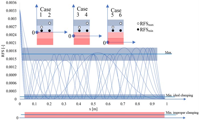
Table 1Damage scenarios and considered output
Damage type | Transverse crack severity [%] | Clamping type | Weak clamping [%] | Output (Case) |
Small damage | 10 to 20 | Ideal clamping | 0 | 1 |
Large damage | 20 to 36 | Ideal clamping | 0 | 2 |
Small damage | 10 to 20 | Strong clamping | 10 to 12 | 3 |
Small damage | 10 to 20 | Weak clamping | 12 to 20 | 4 |
Large damage | 20 to 36 | Strong clamping | 10 to 12 | 5 |
Large damage | 20 to 36 | Weak clamping | 12 to 20 | 6 |
The RFS values are calculated for damage scenarios consisting of transverse cracks with or without ideal clamping conditions. These values are used as input data for training the ANN. As output, we consider the classification of the damage type, where we consider six classifiers numbered from Case 1 to Case 6, describing the presence of a transverse crack, its severity, and the clamping condition. All possible outputs are shown in Table 1, relative to Fig. 1.
3. ANN model
The intelligent model is developed to detect transverse cracks and alterations in the fastening of beams while also evaluating the severity of the overall damage. For this objective, the machine learning module from MATLAB software is used. The development process consists of the training phase, learning phase and model testing. The type of artificial neural network used is feedforward-backpropagation with two hidden layers.
The feedforward network performs the required mathematical operations, to achieve the desired outcome. After performing the initial learning, the error between the resulted and desired outcome is determined and the backpropagation algorithm is employed for minimizing the error by changing the values of the weights and biases so that the network will give more accurate results. To construct a model structure as simple as possible for avoiding overfitting, the Bayesian Regularization training function is used. The number of neurons defined for the network is established by using Eq. (4):
where: – the number of hidden neurons, – number of samples, – the number of input neurons, – the number of output neurons, – scaling factor, which is set to 100.
The model is trained by introducing two inputs consisting of the minimum and maximum RFS values for each damage case and one output value from 1 to 6, relative to the severity of the damage.
The considered scenarios are determined for a cantilever steel beam that is affected at first only by a transverse crack with the severity range considered for a crack depth of 0,1…0,36 [mm], where represents the beams thickness. The range of the dataset is calculated for the severity values in relation to the crack depth , starting with the position of the crack near the fixed end at a distance 2 mm with a step of 2 mm until it reaches 998 mm resulting in 4000 damage signatures just for the cases with one crack and ideal clamping. Furthermore, we generate damage scenarios for a beam with a transverse crack that is affected by improper clamping also by considering the severity as if a transverse crack was present exactly at the fixed end. The considered severity values for the damaged cantilever cases with the structure affected by weak clamping, are equal to 10 %, 12 %, 16 % respectively 20 % of the beam section. Every damage scenario is denoted as , where represents the position of the crack, the transverse crack severity and the weak clamping severity.
To evaluate the gravity of the damage the model is trained to give as output an evaluation of the amount of damage, as defined in Table 1.
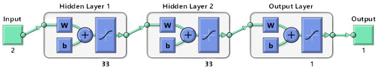
By considering the damage scenarios presented, we used Eq. (3) to generate a database consisting of the RFS values for the first eight weak axis bending vibration modes. As input values for the artificial neural network, for each scenario, we have considered two entries, the minimum and maximum RFS values, resulting in 20.000 input values. With the help of Eq. (4) we define the number of hidden neurons resulting in a network architecture consisting of two hidden layers, each containing 33 neurons, as presented in Fig. 2. After the architecture of the network is defined, the model is trained and evaluated with the help of the plotted validation graph provided by the MATLAB software.
Fig. 2Artificial neural network architecture
4. Experimental validation of the intelligent model
After the training phase, the developed neural network is tested by considering different damage scenarios generated through FEM simulations. All experimental values can be found in the free available online database [15].
We have conducted several simulations, in the ANSYS software, by defining specific damage scenarios. The structure considered is a prismatic cantilever beam with the length 1 m, width 0.02 m, and thickness 0.005 m, made of S355 JR steel applied from the ANSYS database. It is the same beam as that used for training but the training was made with results obtained involving the analytical method.
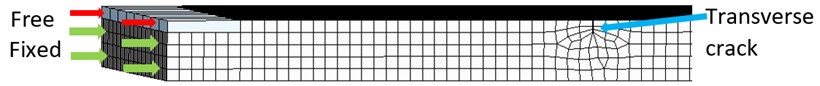
The damage scenarios consist of a transverse crack of different depths (severities) and in some cases, the beam is also affected by a known degree of weak clamping, comprised between 10 % and 20 % of the thickness of the beam. For this purpose, a fine mesh of hexahedral elements with a 1 mm maximum edge size is considered. The crack geometry is generated by cutting of material using a width of 0.04 mm at the desired location and depth with the Extruded Cut command. For the cases with weak clamping, the surface is split by a projection line and the desired clamping alteration is realized by defining the percent of the free surface, marked with red arrows, as presented in Fig. 3. A more detailed explanation of the simulation’s configuration is presented in the paper [16]. After the modal simulations are performed the natural frequencies for the first eight transverse modes of vibrations, for the beam, in an undamaged and damaged state, are recorded and the RFS values are calculated using Eq. (1). For all damage scenario the minimum and maximum values are given to the neural network and the outcome is evaluated.
Fig. 3Simulation beam model
All damage scenarios and the prediction given by the network are shown in Table 2.
From the results shown, one can observe that all predictions are correct, demonstrating the accuracy of the developed method for detecting an alteration in the fastening condition of a beam-type structure.
Table 2Obtained results for the FEM damage scenarios
Defined scenario | Expected output | Predicted output | Defined scenario | Expected output | Predicted Output |
C(81, 12, 0) | 1 | 1 | C(81, 10, 20) | 4 | 4 |
C(173, 10, 0) | 1 | 1 | C(760, 20, 16) | 4 | 4 |
C(687, 24, 0) | 2 | 2 | C(173, 24, 12) | 5 | 5 |
C(760, 36, 0) | 2 | 2 | C(687, 32, 10) | 5 | 5 |
C(81, 10, 12) | 3 | 3 | C(173, 30,16) | 6 | 6 |
C(760, 20, 10) | 3 | 3 | C(687, 36, 20) | 6 | 6 |
5. Conclusions
In the current paper, the authors propose to develop an intelligent model for detecting transverse cracks and the existence of improper clamping in beam-like structures. To this aim, an analytical method for generating the training data consisting of the minimum and maximum RFS values for each damage scenario is presented. The intelligent model relies on a machine learning algorithm that is developed in the MATLAB software. The model is trained to give specific output regarding the extent of the damage. From the results presented, the model demonstrates not only a high accuracy in detecting the presence of damages but also a precise classification of weak clamping and damage severities. The current model could easily be implemented in a more extended intelligent algorithm using the method presented in paper [9], thus predicting the severity and location of the crack and the presence of weak or strong clamping.
References
-
G. Santarsiero, M. Mishra, M. K. Singh, and A. Masi, “Structural health monitoring of exterior beam-column subassemblies through detailed numerical modelling and using various machine learning techniques,” Machine Learning with Applications, Vol. 6, p. 100190, Dec. 2021, https://doi.org/10.1016/j.mlwa.2021.100190
-
K. Dems and J. Turant, “Structural damage identification using frequency and modal changes,” Bulletin of the Polish Academy of Sciences Technical Sciences, Vol. 59, No. 1, pp. 23–32, 2011.
-
H. Nahvi and M. Jabbari, “Crack detection in beams using experimental modal data and finite element model,” International Journal of Mechanical Sciences, Vol. 47, No. 10, pp. 1477–1497, Oct. 2005, https://doi.org/10.1016/j.ijmecsci.2005.06.008
-
P. Das, A. Dutta, and S. Talukdar, “Assessment of damage in prismatic beams using modal parameters,” International Journal on Advanced Science Engineering and Information Technology, Vol. 2, No. 2, p. 192, 2012.
-
M. Karthikeyan, R. Tiwari, and S. Talukdar, “Identification of crack model parameters in a beam from modal parameters,” in 12th National Conference on Machines and Mechanisms (NaCoMM-2005), 2005.
-
I. Hilmy, M. M. A. Wahab, E. Y. T. Adesta, and T. Firdaus, “Damage detection based on the natural frequency shifting of a clamped rectangular plate model,” Journal of Physics: Conference Series, Vol. 628, No. 1, p. 012034, Jul. 2015, https://doi.org/10.1088/1742-6596/628/1/012034
-
D. Lupu, G. R. Gillich, D. Nedelcu, N. Gillich, and T. Manescu, “A method to detect cracks in the beams with imperfect boundary conditions,” Journal of Physics: Conference Series, Vol. 1781, No. 1, p. 012012, Feb. 2021, https://doi.org/10.1088/1742-6596/1781/1/012012
-
G.-R. Gillich et al., “Damage detection on a beam with multiple cracks: a simplified method based on relative frequency shifts,” Sensors, Vol. 21, No. 15, p. 5215, Jul. 2021, https://doi.org/10.3390/s21155215
-
N. Gillich et al., “Beam damage assessment using natural frequency shift and machine learning,” Sensors, Vol. 22, No. 3, p. 1118, Feb. 2022, https://doi.org/10.3390/s22031118
-
D. S. Singha, G. B. L. Chowdarya, and D. R. Mahapatraa, “Structural damage identification using artificial neural network and synthetic data,” arXiv, 2017, https://doi.org/10.48550/arxiv.1703.09651
-
G. R. Gillich, J. L. Ntakpe, M. Abdel Wahab, Z. I. Praisach, and M. C. Mimis, “Damage detection in multi-span beams based on the analysis of frequency changes,” in Journal of Physics: Conference Series, Vol. 842, p. 012033, May 2017, https://doi.org/10.1088/1742-6596/842/1/012033
-
G. R. Gillich, C. Tufisi, Z. I. Korka, C. O. Hamat, and N. Gillich, “Automatic detection of L and T shaped cracks in semifinished casting products,” IOP Conference Series: Materials Science and Engineering, Vol. 393, No. 1, p. 012016, Aug. 2018, https://doi.org/10.1088/1757-899x/393/1/012016
-
G.-R. Gillich, C. Tufisi, M. Abdel Wahab, and C. O. Hamat, “Crack assessment based on the use of severity-adjusted modal curvatures of the healthy beam,” Springer Proceedings in Physics, pp. 499–504, 2021, https://doi.org/10.1007/978-3-030-54136-1_50
-
C. Tufisi et al., “Determining the severity of open and closed cracks using the strain energy loss and the Hill-Climbing method,” Applied Sciences, Vol. 12, No. 14, p. 7231, Jul. 2022, https://doi.org/10.3390/app12147231
-
C. Tufisi, “FEM simulation results,” Mendeley Data, Vol. 1, Dec. 2021, https://doi.org/10.17632/dn4pxx6b3m.1
About this article

The authors have not disclosed any funding.
The datasets generated during and/or analyzed during the current study are available from the corresponding author on reasonable request.
The authors declare that they have no conflict of interest.
