Abstract
Structural health monitoring plays a crucial role in ensuring the integrity and safety of engineering structures such as steel beams. This research paper presents a comprehensive methodology for detecting transverse cracks in beams with a constant section and any boundary conditions. The proposed approach utilizes the normalized squared modal curvature of the beam, the damage severity, and the natural frequency of the undamaged beam. By analyzing the natural frequencies of both the undamaged and damaged states, Relative Frequency Shift (RFS) values are obtained. Subsequently, the Damage Location Coefficients (DLC) are calculated by normalizing the RFS values. These DLC values are then employed to establish a comprehensive database of known damage signatures, enabling the training of an artificial neural network (ANN) in MATLAB. The trained ANN can predict the locations of damages for new scenarios by utilizing DLC values obtained from measurements. To validate the effectiveness of the ANN, extensive simulations using Finite Element Method (FEM) and experimental measurements are conducted on a steel cantilever beam. The results demonstrate the ANN’s capability to accurately predict the locations of transverse cracks, showcasing its potential as a reliable tool for structural health monitoring of steel beams.
1. Introduction
Steel beams are widely used in various structural applications, and their integrity is of vital importance to ensure the safety and reliability of engineered systems. Transverse cracks can significantly compromise the structural performance of steel beams, leading to potential catastrophic failures if left undetected. Therefore, the development of effective techniques for early detection and localization of transverse cracks is crucial for structural health monitoring and maintenance practices [1]. Numerous methods have been proposed for crack detection in steel structures, including visual inspection, ultrasonic testing, magnetic particle inspection, and vibration-based techniques [2]. Among these, vibration-based approaches have gained considerable attention due to their non-destructive nature and ability to detect incipient cracks [3].
In recent years, the use of measured natural frequencies and modal parameters has emerged as a promising approach for crack detection in steel beams [4]. Numerous researchers [4, 5] have investigated the relationship between crack-induced changes in modal parameters and have demonstrated that changes in the natural frequencies of a beam can be indicative of crack presence and location.
One notable algorithm developed for calculating the natural frequencies of beams affected by transverse cracks is based on the normalized squared modal curvature, damage severity, and the undamaged natural frequency of the beam [5]. This algorithm allows for accurate determination of the damage severity and location along the beam. However, the challenge lies in utilizing these calculated natural frequencies to effectively detect and locate cracks in real-world scenarios. To address this, researchers have proposed the use of the Relative Frequency Shift (RFS) values, obtained by comparing the natural frequencies of the undamaged and damaged states [6, 7]. The RFS values can be further normalized to obtain Damage Location Coefficients (DLC), which serve as signatures for different crack scenarios. To harness the full potential of the DLC values and facilitate practical crack detection, this research paper proposes the utilization of an artificial neural network (ANN) [8]. The ANN is trained using a comprehensive database of known damage signatures created from DLC values, enabling accurate prediction of the position of cracks for new damage scenarios. The effectiveness of the ANN is evaluated through both FEM simulations and experimental measurements performed on a steel cantilever beam [8, 9].
2. Generating the damage scenarios
In this section, we present a mathematical relation that can be employed to determine the RFS values of a beam with any boundary condition, by using the required squared normalized modal curvature and the damage severity [10, 11]. This facilitates the development of a database that establishes a connection between the position of the crack and the decrease in natural frequencies of bending vibration modes. The mathematical relation is:
In this context, we represent the position of the crack as , the depth of the crack as , and represents the mode number. By using Eq. (1), we can derive the relative frequency shift (RFS) values, which refer to the normalized decrease in frequency caused by a crack:
The crack severity is evaluated using an energy-based approach, which states that a beam with a crack will have a reduced energy storage capacity compared to a similar crack-free beam [8]. Additionally, the cracked beam will experience greater deformation when subjected to a force [9]. Therefore, we can quantify the severity by utilizing a mathematical relationship [10]:
where, we used the notation to represent the deflection of the healthy beam and to represent the deflection of a beam with a crack of depth . Afterward, Eq. (4) can be employed for obtaining the DLC values for any crack position by dividing all RFS by the maximum value of the series, thus removing the effect of the severity:
By using the described approach, one can easily create a database containing the analytically contrived DLC values and because the effect of the damage severity is reduced, the DLC values will be repeated several times because they remain similar to other values for every specific damage location, thus assuring a better training of the ANN.
3. Training a feedforward ANN with backpropagation
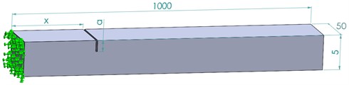
In this section, the development of a feedforward Artificial Neural Network (ANN) with backpropagation using the calculated DLC values for several scenarios of transverse open cracks with different depths is presented. The ANN serves as a predictive tool to accurately determine the position of cracks in a steel cantilever beam with the dimensions presented in Fig. 1. The damage scenario database required for training the ANN is calculated by removing the transverse crack with a step of 2 mm and by considering the severity values starting from 10 % and reaching 36 % relative to the beam’s thickness. The considered severity values are shown in Table 1.
Table 1Considered severity values
Severity | Crack depth [mm] | Severity | Crack depth [mm] |
0.000866543 | 0.5 | 0.005123933 | 1.2 |
0.001191134 | 0.6 | 0.007104848 | 1.4 |
0.002140983 | 0.8 | 0.009516999 | 1.6 |
0.003345971 | 1 | 0.012434481 | 2 |
Fig. 1Main dimensions of the cantilever beam
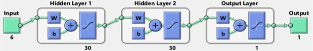
To develop the ANN, a large database of known damage signatures is created by analytically generating different crack scenarios considering the DLC values for the first six transverse vibration modes of a steel cantilever beam. These scenarios involve the consideration of transverse cracks at various positions and depths along the beam. The corresponding DLC values for each damage scenario are calculated using the previously described methodology. The ANN is trained using this database, where the DLC values serve as the input and the corresponding crack positions as the target output. The feedforward ANN architecture is chosen due to its simplicity and effectiveness in learning complex patterns and relationships. The ANN consists of an input layer, two hidden layers of 30 neurons each, and an output layer as shown in Fig. 2.
Fig. 2The structure of the ANN
The number of nodes in the input layer of the artificial neural network (ANN) is determined based on the DLC values obtained from the measurements. The training process of the ANN involves the application of the backpropagation algorithm, which encompasses two primary phases: forward propagation and backward propagation. During the forward propagation phase, the input DLC values are introduced into the ANN, and the neurons' weighted sums and activations are computed for each layer. This computation continues until the output layer is reached, resulting in the prediction of the crack position. Once the predicted crack position is obtained, it is compared to the actual crack position to determine the error. In the subsequent backward propagation phase, the weights and biases of the network’s neurons are adjusted to minimize this error. During the training phase, the performance of the ANN is continuously evaluated using validation data that is separate from the training dataset as 70 % for training, 15 % for validation, and 15 % for testing. This helps prevent overfitting and ensures the generalization of the network to new, unseen damage scenarios. Once the training process is completed, the ANN is capable of accurately predicting the position of cracks for new damage scenarios. These new scenarios can be obtained by inserting DLC values from measurements into the trained ANN. The network takes these DLC values as input and generates the predicted crack position as the output.
4. Testing the developed ANN
By utilizing FEM simulations and experimental measurements on the steel cantilever beam, the performance and accuracy of the ANN can be assessed. This evaluation provides insights into the reliability and effectiveness of the developed ANN in detecting and localizing transverse cracks in steel beams.
The FEM modal simulations are performed in ANSYS. The process of defining the FEM analysis starts with creating the geometry according to the specified dimensions in Fig. 1. After defining the geometry, the necessary constraints are applied to simulate a cantilever beam by completely fixing one end of the beam to represent rigid fixation while leaving the other end free.
Next, the material is assigned to the beam, which in this study is Structural Steel, having the parameters 210000 MPa and 7850 kg/m3.
Once the geometry, constraints, and material properties are set, the mesh is generated by using hexahedral elements of 2 mm maximum edge size, and the simulations are performed to extract the transverse vibration natural frequencies [12].
To simulate the presence of transverse cracks, the beam geometry is modified by cutting material with a specified width to represent the crack. The crack depth can be varied to simulate different levels of damage. Modal simulations are then conducted for the damaged beam configurations to obtain the natural frequencies in the presence of the crack [13].
After obtaining the natural frequencies for both the intact and damaged states, the Damage Location Coefficients (DLC) are calculated using the previously described methodology. These DLC values are then introduced into the trained ANN to predict the position of cracks. The accuracy of the ANN predictions can be evaluated by comparing them with the actual crack positions and assessing the performance of the network in detecting and localizing transverse cracks in the steel beam.
The defined FEM scenarios and DLC values which represent the input data are presented in Table 2.
Table 2Considered FEM damage scenarios
Target | Input DLC | ||||||
Damage location [mm] | Damage depth [mm] | Mode 1 | Mode 2 | Mode 3 | Mode 4 | Mode 5 | Mode 6 |
10 | 1 | 1 | 0.928371 | 0.870600 | 0.809829 | 0.750017 | 0.696220 |
55 | 1 | 1 | 0.635838 | 0.386356 | 0.196689 | 0.072116 | 0.015072 |
125 | 1 | 1 | 0.250022 | 0.017397 | 0.110020 | 0.364902 | 0.581511 |
363 | 1 | 0.614741 | 0.589864 | 0.809845 | 0.025322 | 1 | 0.596311 |
489 | 1 | 0.258190 | 1 | 0.023941 | 0.985002 | 0.035263 | 0.954652 |
604 | 1 | 0.122845 | 0.948614 | 0.612107 | 0.184099 | 1 | 0.062169 |
806 | 1 | 0.019223 | 0.158862 | 0.619890 | 1 | 0.833998 | 0.290839 |
870 | 1 | 0.014165 | 0.049472 | 0.223409 | 0.533812 | 0.846319 | 1 |
10 | 0.4 | 1 | 0.926822 | 0.894199 | 0.828445 | 0.759512 | 0.713162 |
55 | 1.6 | 1 | 0.633811 | 0.380316 | 0.190113 | 0.068483 | 0.010626 |
125 | 1.6 | 1 | 0.244426 | 0.008748 | 0.103481 | 0.362654 | 0.577921 |
363 | 1.6 | 0.601884 | 0.586747 | 0.800737 | 0.013022 | 1 | 0.585798 |
489 | 1.6 | 0.254437 | 1 | 0.010733 | 0.978212 | 0.029111 | 0.946661 |
604 | 0.4 | 0.158731 | 0.964829 | 0.689273 | 0.262632 | 1 | 0.127196 |
806 | 1.6 | 0.009289 | 0.152873 | 0.622442 | 1 | 0.826174 | 0.282909 |
870 | 0.4 | 0.077283 | 0.106428 | 0.297039 | 0.578020 | 0.860721 | 1 |
It can be observed from Table 2 that for different damage depths, even if the crack location is the same the DLC values have a small similarity, but because of the simulation and meshing errors the DLC are not identical, making it harder to detect the damage location, thus simulating the use of noisy data.
In our previous research [8], we performed measurements on a real cantilever steel beam with the same dimensions as shown in Fig. 1. The beam was fixed in a vise to ensure stability during measurement. To determine the beam’s natural frequency, we employed an excitation method using a loudspeaker. The loudspeaker was positioned near the beam and generated a controlled vibration at the required frequency for every mode of vibration, that excited the beam into oscillation.
To capture the response of the beam, we used a piezoelectric sensor. The sensor was placed at the free end of the beam to measure the acceleration data. The piezoelectric sensor converted the physical vibrations into electrical signals, which were then transferred through an interface to a computer for further analysis.
We utilized LabVIEW software to process the acquired signals and enhance their accurate readability. LabVIEW provided a user-friendly interface that allowed us to analyze and manipulate the captured data. We implemented signal processing techniques, such as filtering and spectral analysis, to extract the relevant information related to the beam's natural frequencies. Furthermore, to complement the capabilities of LabVIEW and enhance the accuracy of the analysis, we employed previously developed software in Python [8, 9]. This custom software, designed specifically for our research purposes, implemented advanced algorithms and statistical methods to further process the data and extract precise measurements of the natural frequencies. By combining the capabilities of LabVIEW and our custom Python software, we were able to effectively analyze and interpret the measured acceleration data to determine the natural frequencies of the cantilever steel beam. The experimental damage scenarios and DLC values which represent the target and input data are presented in Table 3.
Table 3Considered experimental damage scenarios.
Target | Input DLC | ||||||
Damage location [mm] | Damage depth [mm] | Mode 1 | Mode 2 | Mode 3 | Mode 4 | Mode 5 | Mode 6 |
310 | 0.8 | 0.631578947 | 0.045455 | 0.434783 | 0.831316 | 0.631578947 | 0.045455 |
587 | 1.2 | 0.368421053 | 1 | 0.608696 | 0.148148 | 0.368421053 | 1 |
395 | 1.2 | 0.947368421 | 0.454545 | 0.565217 | 0.762963 | 0.947368421 | 0.454545 |
795 | 2 | 0.263157895 | 0.340909 | 0.130435 | 1 | 0.263157895 | 0.340909 |
5. Obtained results
The obtained simulation values and measurements provided valuable input for our research and allowed us to validate our proposed methods for crack detection and localization using vibration-based techniques.
Table 4Obtained results for the FEM damage scenarios.
Damage location [mm] | Damage depth [mm] | Predicted values | Damage location [mm] | Damage depth [mm] | Predicted values | ||
Location [mm] | Error [%] | Location [mm] | Error [%] | ||||
10 | 1 | 10.3 | 0.03 % | 10 | 0.4 | 9.9 | 0.01 |
55 | 1 | 53.9 | 0.11 % | 55 | 1.6 | 54.5 | 0.05 |
125 | 1 | 118.2 | 0.68 % | 125 | 1.6 | 121.1 | 0.39 |
363 | 1 | 350.5 | 1.25 % | 363 | 1.6 | 357.5 | 0.55 |
489 | 1 | 486.5 | 0.25 % | 489 | 1.6 | 489.9 | 0.09 |
604 | 1 | 594.2 | 0.98 % | 604 | 0.4 | 598.9 | 0.51 |
806 | 1 | 799.2 | 0.68 % | 806 | 1.6 | 803 | 0.30 |
870 | 1 | 869.5 | 0.05 % | 870 | 0.4 | 870 | 0.00 |
The results obtained for the FEM scenarios are presented in Table 4 and the results obtained for the experimental scenarios are presented in Table 5.
Table 5Obtained results for the experimental damage scenarios
Damage location [mm] | Damage depth [mm] | Predicted values | Damage location [mm] | Damage depth [mm] | Predicted values | ||
Location [mm] | Error [%] | Location [mm] | Error [%] | ||||
310 | 0.8 | 285.9 | 2.41 | 395 | 1.2 | 372.1 | 2.29 |
587 | 1.2 | 557.5 | 2.95 | 795 | 2 | 799.5 | 0.45 |
6. Conclusions
This research paper presented a comprehensive approach for detecting and localizing transverse cracks in steel beams using natural frequencies. The developed algorithm, based on normalized squared modal curvature, damage severity, and undamaged natural frequency, are used for calculating the Damage Location Coefficients (DLC) for various damage scenarios. These DLC values were then used to train an artificial neural network (ANN) capable of predicting the position of cracks.
The results obtained from Finite Element Method (FEM) simulations demonstrated the accuracy of the proposed approach, with a maximum error of 1.25 % in localizing damages. The ANN successfully predicted the crack positions for new damage scenarios based on DLC values, indicating its capability to generalize and provide accurate predictions.
In the approach, when considering laboratory experiments with real cantilever steel beams, slightly larger errors were observed, but within acceptable limits. The maximum error in localizing damages for the measured laboratory experiments did not exceed 2.95 %.
Nonetheless, the overall performance of the approach, as evidenced by the FEM simulations and laboratory experiments, highlights its potential for practical implementation in structural health monitoring systems.
References
-
Wei Fan and Pizhong Qiao, “Vibration-based damage identification methods: a review and comparative study,” Structural Health Monitoring, Vol. 10, No. 1, pp. 83–111, Jan. 2011, https://doi.org/10.1177/1475921710365419
-
P. Cawley and R. Adams, “The location of defects in structures from measurements of natural frequencies,” Journal of Strain Analysis for Engineering Design, Vol. 34, No. 2, pp. 85-94, 1999.
-
P. Cawley and R. D. Adams, “The location of defects in structures from measurements of natural frequencies,” The Journal of Strain Analysis for Engineering Design, Vol. 14, No. 2, pp. 49–57, Apr. 1979, https://doi.org/10.1243/03093247v142049
-
Y. Yang, Y. Zhang, and X. Tan, “Review on vibration-based structural health monitoring techniques and technical codes,” Symmetry, Vol. 13, No. 11, p. 1998, Oct. 2021, https://doi.org/10.3390/sym13111998
-
P. K. Umesha, R. Ravichandran, and K. Sivasubramanian, “Crack detection and quantification in beams using wavelets,” Computer-Aided Civil and Infrastructure Engineering, Vol. 24, No. 8, pp. 593–607, Nov. 2009, https://doi.org/10.1111/j.1467-8667.2009.00618.x
-
G.-R. Gillich et al., “Damage detection on a beam with multiple cracks: a simplified method based on relative frequency shifts,” Sensors, Vol. 21, No. 15, p. 5215, Jul. 2021, https://doi.org/10.3390/s21155215
-
T. G. Chondros, A. D. Dimarogonas, and J. Yao, “A continuous cracked beam vibration theory,” Journal of Sound and Vibration, Vol. 215, No. 1, pp. 17–34, Aug. 1998, https://doi.org/10.1006/jsvi.1998.1640
-
N. Gillich et al., “Beam damage assessment using natural frequency shift and machine learning,” Sensors, Vol. 22, No. 3, p. 1118, Feb. 2022, https://doi.org/10.3390/s22031118
-
C. Tufisi et al., “Determining the severity of open and closed cracks using the strain energy loss and the Hill-Climbing method,” Applied Sciences, Vol. 12, No. 14, p. 7231, Jul. 2022, https://doi.org/10.3390/app12147231
-
C. Tufisi, G. R. Gillich, C. I. Barbinta, D. Nedelcu, and C. O. Hamat, “A new predictive model to estimate the frequencies for beams with branched cracks,” in IOP Conference Series: Materials Science and Engineering, Vol. 997, No. 1, p. 012063, Dec. 2020, https://doi.org/10.1088/1757-899x/997/1/012063
-
Cristian Tufisi, Nicoleta Gillich, Mario Ardeljan, Rusalin Lucian Paun, and Gilbert-Rainer Gillich, “A cost function to assess cracks in simply supported beams with artificial intelligence,” Romanian Journal of Acoustics and Vibration, Vol. 18, No. 1, pp. 46–52, Jul. 2021.
-
M.-V. Pop, C. Tufisi, and G.-R. Gillich, “Determining the position of two cracks in a cantilever beam using artificial neural networks,” Vibroengineering PROCEDIA, Vol. 46, pp. 14–20, Nov. 2022, https://doi.org/10.21595/vp.2022.22928
-
N. Touat M. Dahak and M. Kharoubi, “Damage detection in beam through change in measured frequency and undamaged curvature mode shape,” Inverse Problems in Science and Engineering, Vol. 27, No. 1, pp. 89–114, 2019.
About this article

The authors have not disclosed any funding.
The datasets generated during and/or analyzed during the current study are available from the corresponding author on reasonable request.
The authors declare that they have no conflict of interest.
