Abstract
This paper presents a two-step method for damage localization in beams by combining natural frequencies and mode shapes. The general locations of the damage are first identified from an indicator developed using relative natural frequency change (RNFC) curves and the values of RNFCs. A curvature-mode-shape-based method is then utilized to determine the specific location of the damage in the second step. The proposed two-step method is verified by detecting damage in a simulated simply-supported beam. The identified damage location agrees well with the actual damage location. A strategy for fast and accurate damage localization based on general localization using natural frequencies and specific localization using mode shapes is the main novelty of the paper.
1. Introduction
Vibration-based damage detection has been widely investigated in the past decades and is still an ongoing research focus in the civil, mechanical, and aerospace industries [1-3]. The basic premise of this group of methods is that damage in a structure will cause changes in structural modal parameters (natural frequencies, mode shapes, and modal damping), which in turn indicate the presence, location, and size of damage [2]. Damage detection using natural frequencies is mostly based on the solution of the inverse problem [4, 5]. This requires a prior knowledge of material properties and geometrical dimensions of the inspected structure. The authors developed a damage indicator by combining damage-induced relative natural frequency change (RNFC) curves and the values of RNFCs [6, 7]. The indicator was successfully used for damage localization in beam-like structures without knowledge of material properties and geometrical dimensions. However, there is a limitation that the indicator always stands out in a pair of areas including damage area and its symmetrical counterpart. To solve this problem, a two-step method is proposed in this study. The pair of areas covering damage are determined from the indicator in the first step. Mode shapes in the predetermined areas are then extracted and the corresponding curvature mode shapes are calculated and used to identify the specific location of damage in the second step. Compared to mode shapes, curvature mode shapes are more sensitive to damage and have been successfully used in damage detection [8, 9].
The rest of this paper is organized as follows. Section 2 formulates the two-step method. Section 3 provides a numerical case of a simply-supported beam with damage to verify the feasibility of the proposed method. Conclusions are given in Section 4.
2. Method formulation
2.1. Step 1: natural frequency-based general localization
Damage-induced RNFC curves in beams are denoted as with being the mode number and being the dimensional coordinate. The RNFC curves of a simply-supported beam can be obtained as [6, 7, 10]:
Natural frequencies of a beam before and after damage are known as and . The damage indicator is defined as follows [6, 7].
Unity-based normalization of RNFCs:
where represent RNFCs and are the normalized RNFCs.
Damage position function (DPF) curves:
where is the element number and is the dimensionless coordinate of the th element.
Fusion of multiple DPF curves:
where is called the Bayesian probability and is the fused mode number.
Improvement of Bayesian probability:
where is the maximum element number.
Z-score normalization:
where and are the mean and standard deviation of , respectively.
Probabilistic damage indicator (PDI):
The general locations of damage are indicated by the peaks in PDI.
2.2. Step 2: Mode shape-based specific localization
After determining the general locations of damage, the mode shapes of the areas covering the general locations are extracted and are denoted as . The curvature mode shapes can be approximated by the second-order central difference of mode shapes as:
where represent the curvature mode shapes and is the distance between two successive measured points.
3. Method verification
A simply-supported beam with dimensions of 1000×20×10 mm3 was simulated using a one dimensional beam model with 500 elements. The material properties of the beam model are as follows: elastic modulus 69 GPa and density 2720 kg/m3. Damage is simulated via a 20 % reduction in the elastic modulus of the 150th element. The dimensionless coordinate of the damage element is 0.3. The first six natural frequencies of the beam model before and after damage are shown in Table 1.
Table 1Natural frequencies of the beam model before and after damage (Hz)
State | Mode 1 | Mode 2 | Mode 3 | Mode 4 | Mode 5 | Mode 6 |
Intact | 22.84 | 91.31 | 205.31 | 364.67 | 569.14 | 818.42 |
Damaged | 22.83 | 91.27 | 205.30 | 364.61 | 568.86 | 818.27 |
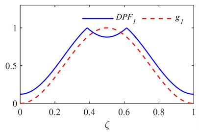
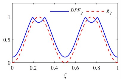
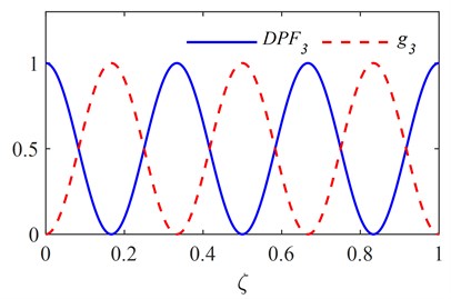
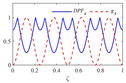
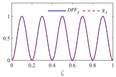
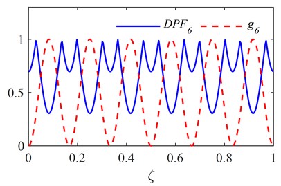
The first six RNFC curves and DPF curves are calculated as described in section 2.1 and are shown in Fig. 1. The PDI is obtained by fusing the first six DPF curves and is plotted in Fig. 2, in which the red dashed line indicates the actual damage location. It is clear from Fig. 2 that two symmetrical peaks stand out at the locations of damage and its symmetrical counterpart.
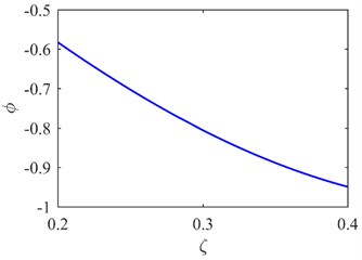
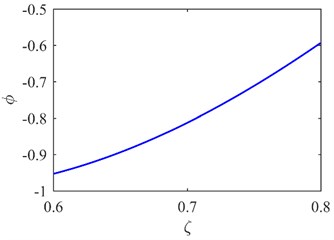
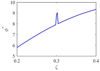
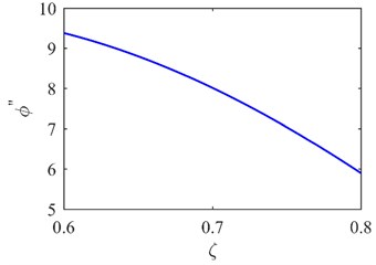
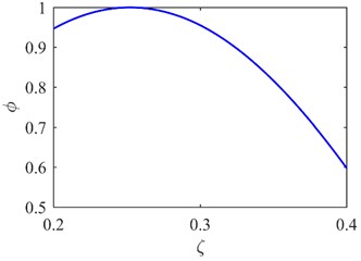
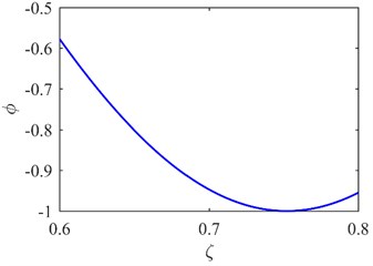
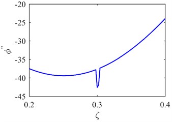
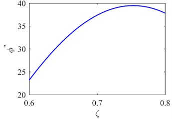
The first mode shapes of two areas (A1 and A2 in Fig. 3) covering the predetermined symmetrical locations are extracted as shown in Fig. 4(a) and (b). The corresponding curvature mode shapes are presented in Fig. 4(c) and (d). The specific damage location is identified from the singularity in Fig. 4(c). The result can be also seen from the second mode shapes and curvature mode shapes in Fig. 5.
It is noteworthy that the curvature mode shape is susceptible to any slight noise since the second-order central difference used to generate a mode shape curvature considerably amplifies any slight noise in the mode shape [11]. Thus, the ability of the proposed method to detect damage will be possibly frustrated under noisy conditions.
Fig. 1First six RNFC curves and DPF curves
a)
b)
c)
d)
e)
f)
Fig. 2PDI obtained by fusing the first six DPF curves
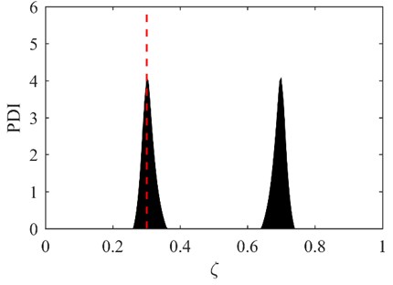
Fig. 3The areas where mode shapes are measured
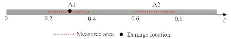
Fig. 4The first mode shape a) and curvature mode shape c) of A1; the first mode shape b) and curvature mode shape d) of A2
a)
b)
c)
d)
Fig. 5The second mode shape a) and curvature mode shape c) of A1; the second mode shape b) and curvature mode shape d) of A2
a)
b)
c)
d)
4. Conclusions
A two-step method for damage localization in beams is proposed in this study. The general locations of the damage are identified from an indicator developed using RNFC curves and the values of RNFCs in the first step. A curvature mode shape-based method is then used to identify the specific location of the damage in the second step. The effectiveness of the two-step method is confirmed by detecting damage in a simulated simply-supported beam.
References
-
D. Nedelcu and G.-R. Gillich, “A structural health monitoring Python code to detect small changes in frequencies,” Mechanical Systems and Signal Processing, Vol. 147, p. 107087, Jan. 2021, https://doi.org/10.1016/j.ymssp.2020.107087
-
G. Sha, R. Soman, M. Radzieński, M. Cao, W. Ostachowicz, and H. Zuo, “A two-step method for additional mass identification in beam structures by measurements of natural frequencies and guided waves,” Measurement, Vol. 186, p. 110049, Dec. 2021, https://doi.org/10.1016/j.measurement.2021.110049
-
M. S. Cao, G. G. Sha, Y. F. Gao, and W. Ostachowicz, “Structural damage identification using damping: a compendium of uses and features,” Smart Materials and Structures, Vol. 26, No. 4, p. 043001, Apr. 2017, https://doi.org/10.1088/1361-665x/aa550a
-
O. S. Salawu, “Detection of structural damage through changes in frequency: a review,” Engineering Structures, Vol. 19, No. 9, pp. 718–723, Sep. 1997, https://doi.org/10.1016/s0141-0296(96)00149-6
-
M. Dahak, N. Touat, and M. Kharoubi, “Damage detection in beam through change in measured frequency and undamaged curvature mode shape,” Inverse Problems in Science and Engineering, Vol. 27, No. 1, pp. 89–114, Jan. 2019, https://doi.org/10.1080/17415977.2018.1442834
-
G. Sha, M. Radzieński, M. Cao, and W. Ostachowicz, “A novel method for single and multiple damage detection in beams using relative natural frequency changes,” Mechanical Systems and Signal Processing, Vol. 132, pp. 335–352, Oct. 2019, https://doi.org/10.1016/j.ymssp.2019.06.027
-
G. Sha, M. Cao, J. Liu, R. Soman, M. Radzieński, and W. Ostachowicz, “Vibration-based damage growth monitoring in beam-like structures,” Vibroengineering PROCEDIA, Vol. 28, pp. 12–17, Oct. 2019, https://doi.org/10.21595/vp.2019.21085
-
A. K. Pandey, M. Biswas, and M. M. Samman, “Damage detection from changes in curvature mode shapes,” Journal of Sound and Vibration, Vol. 145, No. 2, pp. 321–332, Mar. 1991, https://doi.org/10.1016/0022-460x(91)90595-b
-
M. Cao, M. Radzieński, W. Xu, and W. Ostachowicz, “Identification of multiple damage in beams based on robust curvature mode shapes,” Mechanical Systems and Signal Processing, Vol. 46, No. 2, pp. 468–480, Jun. 2014, https://doi.org/10.1016/j.ymssp.2014.01.004
-
S. S. Rao, Vibration of Continuous Systems. New York: Wiley, 2007.
-
M. Chandrashekhar and R. Ganguli, “Damage assessment of structures with uncertainty by using mode-shape curvatures and fuzzy logic,” Journal of Sound and Vibration, Vol. 326, No. 3-5, pp. 939–957, Oct. 2009, https://doi.org/10.1016/j.jsv.2009.05.030
About this article

This work is partially supported by the National Natural Science Foundation of China (Nos. 12102184 and U1933202), the Natural Science Foundation of Jiangsu Province of China (No. BK20210270), and the Anhui Provincial International Joint Research Center of Data Diagnosis and Smart Maintenance on Bridge Structures (No. 2021AHGHYB02).
The datasets generated during and/or analyzed during the current study are available from the corresponding author on reasonable request.
The authors declare that they have no conflict of interest.
