Abstract
The paper presents the natural frequencies shift of a Warren truss with seven elements in the case that members of the structure are weakened by considering that the modulus of elasticity with a lower value. Taking into consideration that the slenderness ratio has a constant value and the transverse section of the truss bars is changed, the relative frequency shift for the first seven vibration mode were calculated by using the values obtained from numerical modal analysis. The conclusions reveal the fact from the dynamic behavior of the structure it can be obtained templates to identify the weakened truss bar of the structure.
1. Introduction
Warren truss are popular structures which are used in various engineering fields. Loads on the truss bars vary between compression and tension and the natural frequency depends upon stiffness and mass distributions and boundary conditions [1].
To determine the natural frequencies for trusses, generally, the finite element method or transfer matrix method can be used [2].
A good literature about natural frequency analysis with the transfer matrix method was published [3, 4] but drawback of this method consists of numerical difficulties when the transfer matrix manipulation involves differences of large numbers and roundoff and truncation errors by the progressive multiplication of transfer matrices [5-7].
In this paper, the numerical modal analysis for a single-span Warren truss with seven elements was used in order to obtain the natural frequencies and comparing them for the same structure, but in which for each element considered as weakened or damaged, the elasticity modulus has been deliberately changed. For the evaluation of the results obtained from the numerical modal analysis, three different cross-sections were considered for the elements of the structure. The paper is focused on the values obtained from finite elements method results by using SolidWorks software.
The analyzed Warren truss consists of a series of equilateral triangles, that means that every truss bar has the same length, and all the elements are hinged at both ends.
Fig. 1Single-span Warren truss with seven bar of equal length
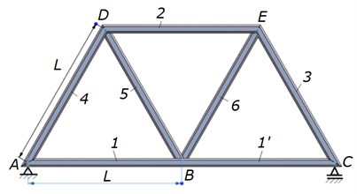
2. Analytical considerations
The analytical approach for a Warren truss (Fig. 1) from the point of view of dynamic behavior starts from the considerations that under the action of its own weight, the structural elements of the truss are subject to tension and compression.
It is known from the literature that in order to determine the longitudinal natural frequencies, the truss bars can have the following boundary conditions:
1) Fixed at one end and free to the other. The axial displacement is given by the relationship:
where is the integration coefficient and are the eigenvalues for the considered 1, 2, …. natural frequencies [Hz]. The values of and are determined from relations Eqs. (2) and (3):
where [m] is the length of the element, [N/m2] is the elastic or Young’s modulus, [kg/m3] is the mass density.
2) Fixed at both ends with axial displacement given with Eq. (1) and and determined from relations Eqs. (4) and (5):
Fig. 2Truss bar D-E
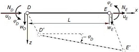
3) The transfer equations of a truss bar (Fig. 2), for example for the element from Fig. 1, are:
where, , – axial displacements at the beginning, , – transverse displacements, , – rotation of nodes and , , – axial forces at nodes and , [m2] – cross sectional area.
For the modal analysis cases presented below, only the values of the natural frequencies obtained from the numerical modal analysis using the finite element method were taken into account.
3. Numerical modal analysis
To visualize the vibration modes and to obtain the natural frequencies of the Warren truss presented in Fig. 1, the modal analysis by the finite element method was used, using the SolidWorks software. All the elements have the same cross section and after FEM analysis it was obtained the first 7 natural frequencies. From the point of view of the material assigned for elements 1 and 1', SolidWorks considers these elements to be a single element. Only from the point of view of modal interpretation, these elements are distinct. The analyzed Warren truss (Fig. 1) has a single-span, simply supported, on which only its own weight acts.
4. Mode shapes
For a Warren truss where all elements have the same length and the same cross section, the modal shapes for the first 7 modes of vibration obtained from FEM analysis are illustrated in Table 1.
Table 1The first seven mode shapes for a single-span Warren truss
Mode shape | |
1 | 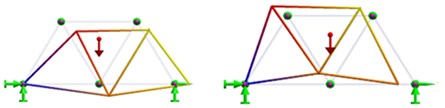 |
2 | 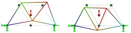 |
3 | 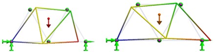 |
4 | 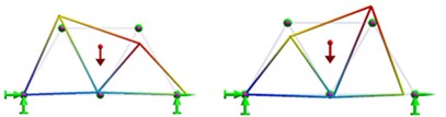 |
5 | 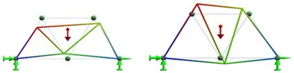 |
6 | 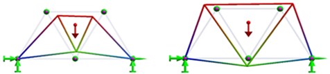 |
7 | 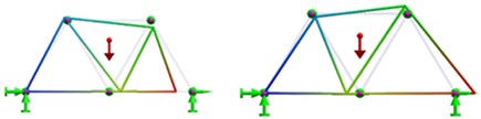 |
5. Analyzed cases
By using modal numerical analysis, the following cases were analyzed:
1) All the truss bars are made of structural steel with 2.1·1011 N/m2. The natural frequencies were determined;
2) One after another, for each truss bar only the modulus of elasticity was reduced with 25 % to value of 1.6·1011 N/m2 considering it as a weakened or damaged structural element. After each modification of the modulus of elasticity for the considered truss bar, the natural frequencies were determined;
3) The natural frequencies obtained by modifying each truss bar were compared with the natural frequencies obtained in the case of the structure is made of the same material. The relative frequencies shift e [%] were calculated with relation Eq. (7):
4) For the cases mentioned above, it was considered three types of truss bar, as follows: rectangular tube 120×80×8; pipe 33,7×4 and square tube 80×80×5;
5) For these three cross section types mentioned above, the length of the truss bar was established so that the slenderness coefficient has the value of:
where [m4] is the moment of inertia of the cross section.
6. Results
For the cases stated above from items: a. to e., below are presented the natural frequency values obtained and the relative frequency shift which have the same value regardless of the cross section chosen.
For Warren truss with truss bars of square tube 80×80×5 mm with: 3.055 m, 1435.62 mm2 and 1314420.61 mm4, the natural frequencies for the first seven vibration modes are presented in Table 2.
The notation used for the truss bar with the modified modulus of elasticity is the one used in Fig. 1.
Table 2Natural frequencies, truss bars of square tube 80×80×5 mm
Modified truss bar | [Hz] | [Hz] | [Hz] | [Hz] | [Hz] | [Hz] | [Hz] |
– | 94.501 | 126.35 | 221.51 | 247.46 | 317.97 | 369.96 | 397.57 |
1 – 1’ | 85.991 | 124.51 | 214.86 | 236.1 | 316.11 | 365.01 | 370.14 |
2 | 93.735 | 123.18 | 220.08 | 246.48 | 305.02 | 350.29 | 397.09 |
3 | 91.539 | 125.39 | 210.88 | 244.45 | 312.85 | 367.93 | 390.18 |
4 | 94.329 | 118.27 | 215.86 | 243.48 | 309.95 | 367.84 | 397.55 |
5 | 94.439 | 121.86 | 220.01 | 242.65 | 303.47 | 360.21 | 395.69 |
6 | 93.023 | 126.35 | 212.93 | 239.28 | 316.01 | 355.68 | 394.82 |
Warren truss with truss bars of rectangular tube 120×80×8 mm with: 4.265 m, 2779.19 mm2 and 4957718.55 mm4.
The natural frequencies for the first seven vibration modes are presented in Table 3.
Table 3Natural frequencies, truss bars of rectangular tube 120×80×8 mm
Modified truss bar | [Hz] | [Hz] | [Hz] | [Hz] | [Hz] | [Hz] | [Hz] |
– | 67.69 | 90.502 | 158.67 | 177.26 | 227.76 | 263.57 | 284.78 |
1 – 1’ | 61.595 | 89.193 | 153.900 | 169.12 | 226.43 | 261.45 | 265.13 |
2 | 67.142 | 88.236 | 157.64 | 176.55 | 218.49 | 250.91 | 284.43 |
3 | 65.569 | 89.817 | 151.05 | 175.09 | 224.09 | 263.54 | 279.48 |
4 | 67.568 | 84.713 | 154.62 | 174.4 | 222.02 | 263.46 | 284.76 |
5 | 67.645 | 87.289 | 157.59 | 173.81 | 217.37 | 258.01 | 283.43 |
6 | 66.632 | 90.501 | 152.52 | 171.4 | 226.36 | 254.77 | 282.81 |
Warren truss with truss bars of pipe 33.7×4 mm with: 1.070 m, 373.22 mm2 and 41898.28 mm4.
The natural frequencies for the first seven vibration modes are presented in Table 4.
Table 4Natural frequencies, truss bars of pipe 33.7×4 mm
Modified truss bar | [Hz] | [Hz] | [Hz] | [Hz] | [Hz] | [Hz] | [Hz] |
– | 269.48 | 360.44 | 632.67 | 705.58 | 907.74 | 1050.4 | 1133.7 |
1 – 1’ | 245.21 | 355.12 | 613.75 | 673.07 | 902.42 | 1041.1 | 1056.6 |
2 | 267.27 | 351.45 | 628.55 | 702.74 | 870.97 | 999.87 | 1132.2 |
3 | 261.02 | 357.73 | 602.26 | 697.08 | 893.17 | 1050.3 | 1112.5 |
4 | 268.97 | 337.44 | 616.46 | 694.28 | 884.82 | 1050.0 | 1133.6 |
5 | 269.31 | 347.63 | 628.39 | 692.0 | 866.09 | 1028.4 | 1128.2 |
6 | 265.3 | 360.44 | 608.04 | 682.31 | 902.16 | 1015.2 | 1126.0 |
The relative frequencies shift () computed with relation Eq. (7) for the cases analyzed above are presented in the Table 5 and illustrated in Fig. 3.
Fig. 3Relative frequencies shift patterns
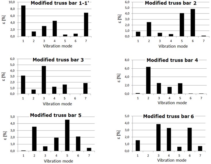
Table 5Relative frequency shift
Modified truss bar | [%] | [%] | [%] | [%] | [%] | [%] | [%] |
1 – 1’ | 9.0 | 1.46 | 3.0 | 4.6 | 0.58 | 0.8 | 6.9 |
2 | 0.8 | 2.5 | 0.7 | 0.4 | 4.1 | 4.8 | 0.1 |
3 | 3.1 | 0.8 | 4.8 | 1.2 | 1.6 | 0.0 | 1.9 |
4 | 0.2 | 6.4 | 2.6 | 1.6 | 2.5 | 0.0 | 0.0 |
5 | 0.1 | 3.6 | 0.7 | 1.9 | 4.6 | 2.1 | 0.5 |
6 | 1.6 | 0.0 | 3.9 | 3.3 | 0.6 | 3.3 | 0.7 |
Analyzing the data obtained from Table 5 and Fig. 3 it can be seen that by reducing the modulus of elasticity by 25 % for each element of the structure, the relative changes of the natural frequencies have the same values regardless of the cross section chosen. Thus, these diagrams illustrated in Fig. 3 can be considered patterns for identifying the weakened element within the structure.
7. Conclusions
In the present paper a numerical modal analysis was performed for a Warren truss in case an element is weakened by the forced modification of the modulus of elasticity. The material used in the modal analysis is structural steel with 2.1·1011 N/m2, and for the weakened truss bar the modulus of elasticity was reduced with 25 % at value of 1.6·1011 N/m2.
The obtained mode shapes from the numerical modal analysis have the same representation even if the modulus of elasticity was reduced with 25 % for each individual truss bar.
The modal analysis for three different cross-sections of the truss bars and considering the slenderness ratio with a constant value of 0.01, revealed the fact that the relative frequency shift, for each individual vibration mode, does not change.
The conclusion from the point of view of dynamic behavior is that if a truss bar of the Warren truss is weakened these patterns can be used in order to identify the weakened truss bar.
By monitoring the natural frequencies on a Warren truss and their comparing with the healthy structure, when a weakened truss bar appears this can be identified, based on the models of relative frequency shift diagrams.
References
-
A. Lahe, A. Braunbruck, and A. Klauson, “An exact solution of truss vibration problems,” Proceedings of the Estonian Academy of Sciences, Vol. 68, pp. 244–263, 2019.
-
E. C. Pestel and F. A. Leckie, Matrix Method in Elastomechanics. New-York: McGraw-Hill, 1963.
-
B. He, X. Rui, and H. Zhang, “Transfer Matrix Method for Natural Vibration Analysis of Tree System,” Mathematical Problems in Engineering, Vol. 2012, pp. 1–19, 2012, https://doi.org/10.1155/2012/393204
-
C. A. Felippa, Q. Guo, and K. C. Park, “Mass matrix templates: general description and 1D examples,” Archives of Computational Methods in Engineering, Vol. 22, No. 1, pp. 1–65, Jan. 2015, https://doi.org/10.1007/s11831-014-9108-x
-
W. Wunderlich and W. D. Pilkey, “Mechanics of structures. Variational and computational methods,” Meccanica, Vol. 39, No. 3, pp. 291–292, Jun. 2004, https://doi.org/10.1023/b:mecc.0000023038.64148.bc
-
N. Fazli, S. M. B. Malaek, A. Abedian, and H. Teimouri, “Development of a new analytical tool to design hierarchical truss beams for natural frequency,” Journal of Mechanical Science and Technology, Vol. 25, No. 10, pp. 2495–2503, Oct. 2011, https://doi.org/10.1007/s12206-011-0733-0
-
C. Millan-Paramo, E. Millan-Romero, and F. Jove, “Truss optimization with natural frequency constraints using Tiki-Taka algorithm,” PalArch’s Journal of Archaeology of Egypt/Egyptology, Vol. 18, No. 5, pp. 304–314, 2021.
About this article

The authors have not disclosed any funding.
The datasets generated during and/or analyzed during the current study are available from the corresponding author on reasonable request.
The authors declare that they have no conflict of interest.
