Abstract
In order to ensure good stability and safety of the tower crane under long-term heavy load conditions, modal analysis and fatigue analysis were conducted on its key components, including standard section and frame section. The connection points of each truss structure were regarded as indivisible common nodes, and the model was simplified and parameterized, resulting in improved mesh quality and computational efficiency. Based on Pro/E, standard section and frame section models were established and imported into Workbench through intermediate data formats for simulation calculations in modal and static structural modules. By calculation, the natural frequency and modal shape of the standard section, as well as the lifespan, damage, and safety factor of the frame section, were obtained. It can be seen that the standard section has good structural stability and can maintain relative balance under excitation in different directions and degrees of freedom. If the safety factor of the web components is high and the service life is improved from a structural perspective, it can be considered to increase the thickness of the chord members.
Highlights
- In order to ensure good stability and safety of the tower crane under long-term heavy load conditions, modal analysis and fatigue analysis were conducted on its key components, including standard section and frame section.
- Based on Pro/E, standard section and frame section models were established and imported into Workbench through intermediate data formats for simulation calculations in modal and static structural modules.
- y calculation, the natural frequency and modal shape of the standard section, as well as the lifespan, damage, and safety factor of the frame section, were obtained.
1. Introduction
According to the characteristics of function and structure, tower cranes can be divided into balance systems, rotating tower systems, boom systems, tower body systems, and chassis systems. Tower cranes are intermittent working equipment that require frequent starting and stopping, which will result in significant sudden loads on key components of the tower crane. Sudden dynamic loads are one of the key factors leading to tower crane failure, which can cause certain vibrations in the fuselage [1, 2]. If the excitation frequency is close to the resonance frequency, it will cause significant damage to the overall structure [3]. Strength and vibration are the main issues that affect the normal operation of tower cranes, and there is an inherent connection between the two. The structural failure caused by vibration mainly comes from fatigue failure, and at the same time, strong vibration has a significant impact on the physical and mental health of operators [4, 5]. Therefore, the modal and strength characteristics of key components of tower cranes are currently the focus of research. Finite Element Analysis is a common engineering analysis method, which converts a complex problem with continuity into a discrete simple problem through mathematical means to solve it, and then gradually solves the problem [6]. The solution values of the finite element analysis results obtained by combining many subsets can be approximated by specific equations for each subset. Generally, the more subsets there are, the closer the final result is to the true result, which can effectively meet the computational requirements in engineering [7]. The finite element model simplifies many complex problems that cannot be solved, so that satisfactory solution values can be obtained. Even if these values are not completely exact solutions, they can fully meet the accuracy requirements in practice and greatly reduce the difficulty of mathematical solving. The finite element analysis method is an indispensable research method in the current engineering field. Although it is an approximate solution, it fully meets the accuracy requirements of engineering design and application. Therefore, based on the finite element method, the modal and fatigue strength of key components of the tower crane can be simulated and analyzed.
2. Modal characteristic analysis of standard sections
2.1. Establishment of the model
The establishment of the finite element model of tower crane components is the first and very important step in numerical simulation. When establishing the key model of tower crane, it is necessary to simplify the actual structure. Due to the fact that most of the boom frame sections and standard sections are welded, considering the efficiency and accuracy of finite element solution, each connection point can be regarded as an inseparable common node connection. In the paper, Pro/E was used to establish a three-dimensional model of the tower body standard section and the lifting arm frame section, and it was imported into Workbench through intermediate data format. The finite element analysis types were selected as modal analysis and static structural analysis.
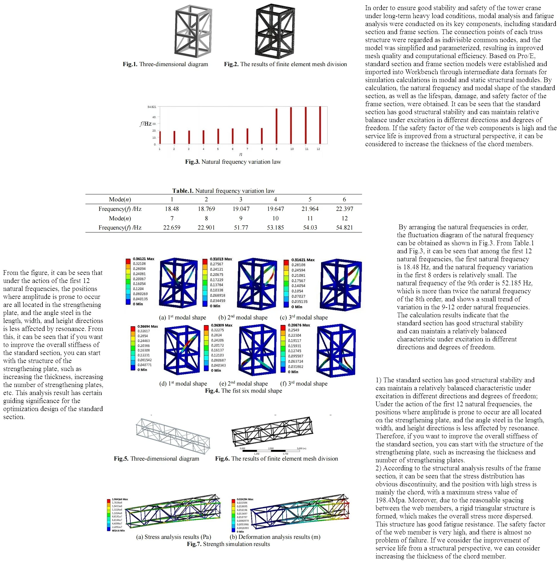
Modal analysis can deeply understand the vibration characteristics of structures, determine the vibration frequency of structures in equipment, reduce the possibility of resonance, and prevent structural damage caused by resonance factors. Due to the fact that the vibration characteristics are independent of external loads and are inherent to the object itself, and damping has little effect on the vibration characteristics, the natural frequency can be calculated using the undamped free vibration equation. Based on the actual structure of the tower crane, a three-dimensional model of the tower body standard section was established using Pro/E as shown in Fig. 1. After saving it in iges format, it was imported into the ANSYS/Workbench analysis model. The selection of finite element analysis type is modal analysis. The basic material properties of the standard section are defined through the material property definition module, and the tetrahedral mesh type is used for mesh division, as shown in Fig. 2.
Fig. 1Three-dimensional diagram
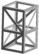
Fig. 2The results of finite element mesh division
2.2. Modal characteristic analysis
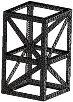
In modal analysis, the degrees of freedom at both ends of the standard section are fully constrained, and the first 12 natural frequencies and vibration modes are calculated. The calculation results of the natural frequency are shown in Table 1. By arranging the natural frequencies in order, the fluctuation diagram of the natural frequency can be obtained as shown in Fig. 3. From Table 1 and Fig. 3, it can be seen that among the first 12 natural frequencies, the first natural frequency is 18.48 Hz, and the natural frequency variation in the first 8 orders is relatively small. The natural frequency of the 9th order is 52.185 Hz, which is more than twice the natural frequency of the 8th order, and shows a small trend of variation in the 9-12 order natural frequencies. The calculation results indicate that the standard section has good structural stability and can maintain a relatively balanced characteristic under excitation in different directions and degrees of freedom.
Fig. 3Natural frequency variation law
Table 1Natural frequency variation law
Mode () | 1 | 2 | 3 | 4 | 5 | 6 |
Frequency () / Hz | 18.48 | 18.769 | 19.047 | 19.647 | 21.964 | 22.397 |
Mode () | 7 | 8 | 9 | 10 | 11 | 12 |
Frequency () / Hz | 22.659 | 22.901 | 51.77 | 53.185 | 54.03 | 54.821 |
The vibration mode diagram of the standard section of the tower body is shown in Fig. 4. From the figure, it can be seen that under the action of the first 12 natural frequencies, the positions where amplitude is prone to occur are all located in the strengthening plate, and the angle steel in the length, width, and height directions is less affected by resonance. From this, it can be seen that if you want to improve the overall stiffness of the standard section, you can start with the structure of the strengthening plate, such as increasing the thickness, increasing the number of strengthening plates, etc. This analysis result has certain guiding significance for the optimization design of the standard section.
Fig. 4The first six modal shape
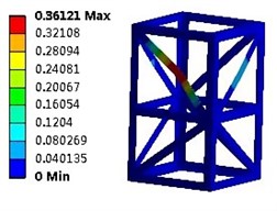
a) 1st modal shape
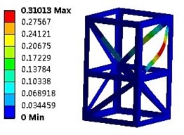
b) 2nd modal shape
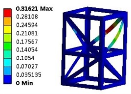
c) 3rd modal shape
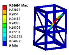
d) 1st modal shape
e) 2nd modal shape
f) 3rd modal shape
3. Analysis of fatigue characteristics of frame section
3.1. Establishment and pre-processing of finite element models
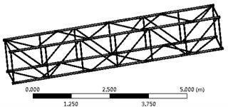
Similarly, establish a three-dimensional model of the frame section in the PRO/E environment, and import it into the finite element analysis software ANSYS/Workben in iges format, as shown in Fig. 5. According to the research plan of the project, the solution type for the research content is determined as static structural analysis, and fatigue calculation is carried out based on the simulation results. The tetrahedral structure mesh and local mesh optimization method were used to partition the frame section, and the mesh diagram is shown in Fig. 6.
According to the load-bearing characteristics of the boom, it can be seen that the ultimate torque borne by the entire boom remains basically unchanged. In other words, the greater the distance from the horizontal direction of the tower, the smaller the weight that can be retracted. The analysis object is the second section at the farthest end of the crane arm, which can lift a weight of 2 tons. According to the equivalent load handling method, the degrees of freedom of the left end face of the frame section are fully constrained, and remote loads are applied to the right end face of the frame section in a concentrated force and bending moment manner. Among them, due to the complexity of wind loads, the article adopts the wind load calculation method summarized by the Shanghai Construction Bureau for solving, mainly including the wind load of lifting heavy objects and the wind load of frame sections.
Fig. 5Three-dimensional diagram
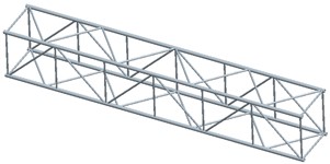
Fig. 6The results of finite element mesh division
3.2. Static strength structural analysis
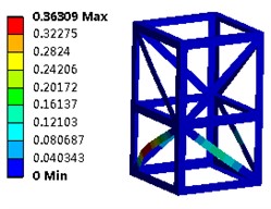
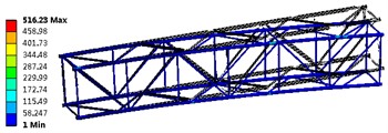
Through continuous iterative operations, the stress and deformation field analysis results of the frame section can be obtained as shown in Fig. 7. In Fig. 7(a), it can be seen that the stress distribution has obvious discontinuity, with the main location of high stress being the chord, and the stress concentration area distributed near the contact between the chord and the web, with a maximum stress value of 198.4 MPa. Moreover, due to the reasonable spacing between the web, a rigid triangular structure is formed, making the overall stress more dispersed. This calculation result meets the required stress range. From Fig. 7(b), it can be seen that the deformation exhibits a significant linear characteristic, with a significant deformation occurring at the rightmost end of the frame section, with a maximum deformation of 24.2 mm, which can be ignored compared to the size of the entire frame section. However, it should be noted that the calculated maximum displacement is relative to the fixed constraint at the leftmost end of the frame section, and it does not reflect the deformation of the entire boom.
Fig. 7Strength simulation results
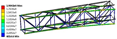
a) Stress analysis results (Pa)
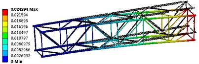
b) Deformation analysis results (m)
3.3. Fatigue characteristic analysis
In order to further analyze the structural characteristics of the frame section, fatigue cyclic stress was applied in the static analysis results, as shown in Fig. 8, and the fatigue characteristics were solved using complete alternating stress. Due to the tower crane being a low-frequency working machinery, the maximum stress is lower than the yield limit. Therefore, the load is applied based on the stress life method in the article, and the calculated maximum cycle life is set to 109.
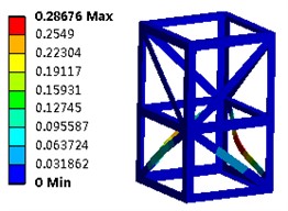
Through calculation, the lifespan cloud map, damage cloud map, and safety factor cloud map of the frame section can be obtained as shown in Fig. 9, and there is a certain correlation between the three results. It can be seen that there is a clear consistency between the life cloud map and the stress cloud map, that is, the fatigue life is shorter at positions with higher stress. The damage cloud map (the ratio of design life to available life) is another manifestation of the life cloud map, and this frame structure has good fatigue resistance. The safety factor of the web member (given a safety factor of 109 cycles, with a maximum value of 15) is very high, and there is almost no failure problem. If considering the improvement of service life from a structural perspective, increasing the thickness of the chord member can be considered.
Fig. 8Properties of fatigue load
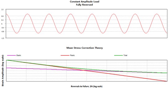
Fig. 9Fatigue characteristic analysis results
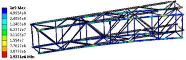
a) Life simulation results
b) Damage analysis results
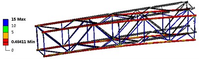
c) Safety factors analysis results
4. Conclusions
1) The standard section has good structural stability and can maintain a relatively balanced characteristic under excitation in different directions and degrees of freedom; Under the action of the first 12 natural frequencies, the positions where amplitude is prone to occur are all located on the strengthening plate, and the angle steel in the length, width, and height directions is less affected by resonance. Therefore, if you want to improve the overall stiffness of the standard section, you can start with the structure of the strengthening plate, such as increasing the thickness and number of strengthening plates.
2) According to the structural analysis results of the frame section, it can be seen that the stress distribution has obvious discontinuity, and the position with high stress is mainly the chord, with a maximum stress value of 198.4 MPa. Moreover, due to the reasonable spacing between the web members, a rigid triangular structure is formed, which makes the overall stress more dispersed. This structure has good fatigue resistance. The safety factor of the web member is very high, and there is almost no problem of failure. If we consider the improvement of service life from a structural perspective, we can consider increasing the thickness of the chord member.
References
-
E. Phongphinittana, C. Sumpavakup, and P. Promdirek, “Optimization of a finite element analysis methodology for predicting the rolling contact fatigue of steels used for APM guide wheel,” Materials Today: Proceedings, Vol. 77, No. 4, pp. 1116–1121, Jan. 2023, https://doi.org/10.1016/j.matpr.2022.12.047
-
S. Baek et al., “Effect of Mg remelting and mechanical hooks of steel on the mechanical and fatigue responses of resistance element welded AZ31/DP780 joints: Experimental, FEM and thermodynamic calculation studies,” Journal of Materials Research and Technology, Vol. 22, No. 1, pp. 1210–1237, Jan. 2023, https://doi.org/10.1016/j.jmrt.2022.11.157
-
A. Daşdemir, “A modal analysis of forced vibration of a piezoelectric plate with initial stress by the finite-element simulation,” Mechanics of Composite Materials, Vol. 58, No. 1, pp. 69–80, Mar. 2022, https://doi.org/10.1007/s11029-022-10012-7
-
V. Santos Arconada and J. García-Barruetabeña, “Development and validation of a simplified nonlinear dynamic model of a passive twin-tube hydraulic shock absorber,” Journal of Vibration and Control, Vol. 27, No. 15-16, pp. 1724–1735, Aug. 2020, https://doi.org/10.1177/1077546320947955
-
V. Nicoletti, R. Martini, L. Amico, S. Carbonari, and F. Gara, “Operational modal analysis for supporting the retrofit design of bridges,” Ce/papers, Vol. 6, No. 5, pp. 1182–1188, Sep. 2023, https://doi.org/10.1002/cepa.2125
-
M. Sohrabifard, M. Nategh, and M. Ghazavi, “Evaluation, calibration, and modal analysis for determination of contact stiffness between workpiece and components of milling fixture,” Proceedings of the Institution of Mechanical Engineers, Part B: Journal of Engineering Manufacture, Vol. 237, No. 12, pp. 1819–1835, Nov. 2022, https://doi.org/10.1177/09544054221138165
-
Slam J. and Hayder A., “Effect of suction pipe diameter and submergence ratio on air lift pumping rate,” Tikrit Journal of Engineering Science, Vol. 16, No. 1, pp. 63–73, 2013, https://doi.org/10.4028/www.scientific.net/amr.1036.703
Cited by
About this article

The authors have not disclosed any funding.
The datasets generated during and/or analyzed during the current study are available from the corresponding author on reasonable request.
The authors declare that they have no conflict of interest.
