Abstract
Cast steel parts can realize rapid prototyping effectively, which is suitable for complex structural design. However, due to the large residual stress, the problem of mechanical property degradation is more obvious. In order to solve this problem, a high temperature excitation vibration treatment scheme is proposed in this paper. By applying different excitation frequencies and impact forces, the effects of mechanical properties and stress corrosion properties are studied and verified. Based on the finite element software ANSYS, the modal shape and resonant frequency of the cast steel parts are obtained, and verified by the sweep frequency module in the excitation vibration system. According to the characteristics of modal shape, five typical detection paths are set, and stress sensors are arranged every 200 mm. In order to obtain the specific effects of excitation frequency and impact force amplitude on mechanical properties, nine parts samples were prepared on the same production line according to the matching requirements of test parameters. In addition, the main external parameters that remain unchanged during vibration excitation are set as initial 750 ℃ and vibration excitation time of 60 s, which can fully affect the effect of austenite transformation. Keeping the synchronization of test parameters in different samples, the distribution rules of residual stress under different excitation frequencies and forces are obtained and analyzed. In the aspect of mechanical properties, the microstructure, hardness, yield strength and tensile strength of the specimens subjected to vibration were compared and analyzed. In the aspect of stress corrosion performance research, stress corrosion cracking test was carried out in weak acid environment to obtain the tensile stress curve and fracture morphology of the specimen. The results show that the excitation vibration at high temperature can effectively eliminate the residual stress of cast steel parts, but the increase of excitation frequency does not correspond to the effect of residual stress elimination. When the exciting force exceeds a certain value, the stress relief effect cannot be further improved. Excitation vibration can reduce the internal hardness of cast steel parts to a certain extent, and improve the yield strength and tensile strength. At the same time, it has a positive role in promoting the improvement of stress corrosion resistance.
Highlights
- Based on the finite element software ANSYS, the modal shape and resonant frequency of the cast steel parts are obtained, and verified by the sweep frequency module in the excitation vibration system.
- In order to obtain the specific effects of excitation frequency and impact force amplitude on mechanical properties, nine parts samples were prepared on the same production line according to the matching requirements of test parameters.
- Keeping the synchronization of test parameters in different samples, the distribution rules of residual stress under different excitation frequencies and forces are obtained and analyzed.
1. Introduction
Cast steel can quickly form a specific mechanical structure after melting at high temperature, with high production efficiency and significant economic benefits. After the liquid steel is injected into the mold, it will preferentially contact the mold wall. The temperature of molten steel in contact with the die wall will drop rapidly, so it is easy to solidify into big grains [1]. With the subsequent pouring of molten steel, the distance from the mold wall will increase. The influence of the die wall will gradually weaken, and the grains will grow into parallel columnar crystals [2] along the vertical part of the die wall. In this way, there is no obvious directivity of heat dissipation in the middle of the casting [3], and it will also grow freely in all aspects until they contact each other, thus forming an equiaxed crystal zone [4]. In this case, the internal structure of the casting is uneven and the grains are relatively rough. The most important advantage of steel castings is their high flexibility. Generally, steel casting manufacturers have great freedom to choose the size and shape of the castings when designing the process, especially for those parts with particularly complex shapes or central control sections, which can be solved by the special process of core assembly. The transformation speed from the design drawings to the finished products is also very fast, which is also conducive to the rapid quotation response of the foundry, and the delivery time will be correspondingly shortened. Therefore, the production process has a wide range of applications in engineering. However, cast steel is prone to stress concentration and thermal load deformation, resulting in its own strength cannot meet the complex load, and its stress corrosion resistance [5] is often poor. At present, the aging [6] and heat treatment [7] methods, which are widely used, can reduce the residual stress to a certain extent, but the cycle is long and the cost is high, which is not conducive to the improvement of production efficiency.
In order to solve these problem, a low frequency vibration processing method is proposed and verified in this paper. Under the high temperature condition of casting forming, periodic external load shall be applied immediately to improve mechanical properties and stress corrosion resistance. This vibration is slight within a certain frequency range, but it can change the structure and refine the grains. At high temperature, the yield limit of the material is very low. Therefore, vibration can easily ease the thermal stress field, easily lead to thermoplastic deformation, and release the constraint strain to reduce the stress field gradient, thus reducing or homogenizing the final welding residual stress. By applying different excitation frequencies and impact forces, the effects of mechanical properties and stress corrosion properties can be verified. In terms of mechanical performance research, it is necessary to compare and analyze the microstructure, hardness, yield strength, and tensile strength of vibration specimens. In the research of stress corrosion cracking (SCC) performance, it is proposed to conduct stress corrosion cracking test in weak acid environment.
2. Design and implementation of exciting vibration scheme
2.1. Principle of exciting vibration
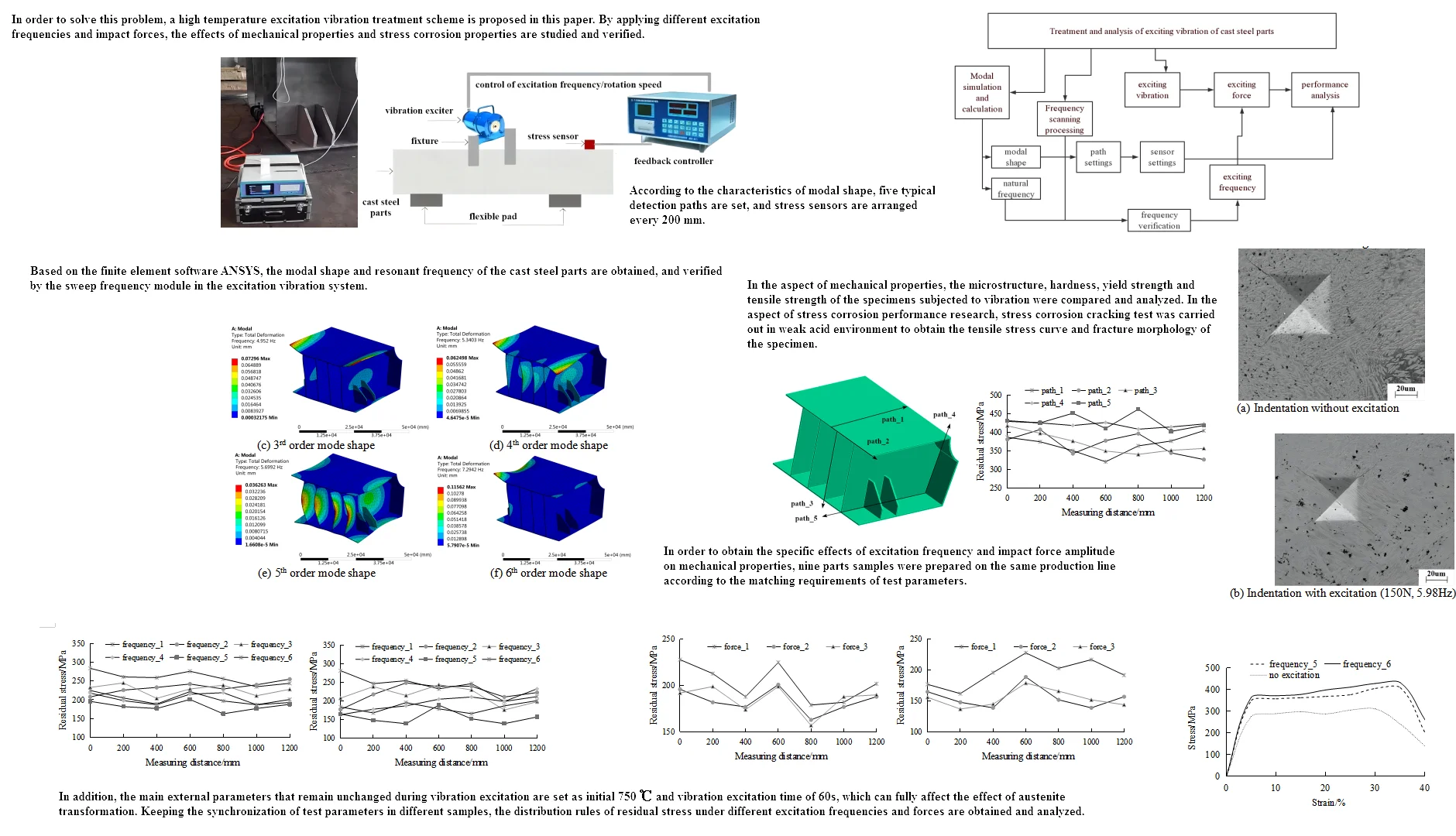
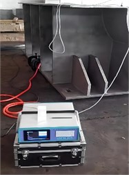
Excitation treatment refers to the periodic external force generated by the vibration exciter. Under the action of the exciting force, the cast steel structure will resonate at a certain frequency to generate enough dynamic stress to eliminate or homogenize the internal residual stress, so as to achieve the aging purpose. Each metal structure has several resonance frequencies of different vibration modes, which are related to the shape, weight, materials and structural stiffness of the structure itself. Excitation vibration equipment can detect several resonance frequencies of different vibration modes through frequency scanning within a certain frequency range [8]. Under normal conditions, the sweep frequency module in the excitation vibration system will automatically select the best resonance frequency as the main vibration frequency and refer to the auxiliary vibration frequency. The whole process is automatically completed by the central processing unit. The interference of human factors on the aging process is avoided. The installation and principle of the excitation vibration system are shown in Fig. 1. The photo in Fig. 1 was taken by the author in vibration laboratory of Qingdao Huanghai University on December 10, 2022. It can be seen that the vibration source is composed of an exciter and a feedback controller, which can monitor the change of residual stress in real time.
In order to ensure that no mechanical damage will occur to the cast steel structure, the vibration frequency is usually selected in the sub resonance area. The sub resonance region is 1/3-2/3 of the maximum amplitude corresponding to the front of the resonance peak. The sub resonance area is selected for vibration treatment, which will not cause any fatigue damage to the structural components, but will improve the fatigue life of the workpiece. The electric reciprocating mechanism is selected as the output mode of the vibration exciter, and the moving coil is made to vibrate under the action of the electromagnetic excitation force in the given magnetic field through alternating current. The constant magnetic field of the exciter is generated by transferring DC to the excitation coil and then AC to the moving coil. The motion coil is driven to and fro by the periodically changing electromagnetic excitation force. The change and adjustment of excitation frequency can be realized by controlling the current.
Fig. 1Installation and principle of exciting vibration system
2.2. Preparation before vibration treatment
Firstly, the elastic rubber pad is placed as a workpiece support near the pitch line. Then, a bow shaped fixture is used to clamp the exciter at the peak position of the workpiece vibration. The magnetic sensor base is fixed on the workpiece, and the exciter, sensor, and controller are connected by dedicated cables. The pitch line is located at the position of the minimum vibration amplitude near the bottom surface, which can be obtained by free mode test. The material of flexible pad is chloroprene rubber, with an effective working temperature of 60 ℃ to –25 ℃. In addition, it is designed as a square plate structure with a plane size of 550 mm × 550 mm and height size of 50 mm. This step is called the preparation process. The support of the workpiece, the clamping position of the vibration exciter and the placement position of the sensor have strict process requirements. Before vibration treatment, the workpiece shall be isolated from the ground and supported by elastic objects such as special rubber pads or waste tire sleeves. The main purpose of support is to isolate vibration and prevent energy from being transmitted to the ground. Because the supporting object first has good elasticity, which avoids the large noise caused by rigid contact.
Secondly, the support position should be selected at the node or node line (wave trough position) of vibration as far as possible, so as to reduce the energy consumption and noise generated by workpiece collision during vibration. There are two main support methods, one is free support, which is used when most workpieces vibrate, and the other is cantilever support. When the workpiece is freely supported, the cantilever support method is very suitable for workpieces with high resonant frequencies. Under the condition of maintaining static and dynamic stability of the workpiece, the number of support points should be minimized as much as possible, otherwise it is not conducive to improving testing accuracy. However, it should be noted that no point of the workpiece can touch the ground, and no point can flatten the support points on the ground. That is to say, the workpiece should not only be completely isolated from the ground, but also the support should be able to support the weight of the workpiece without being overweight.
2.3. Main steps of vibration process
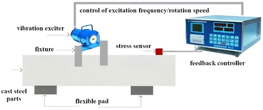
The exciting vibrator automatically detects the natural resonance frequency of the aged workpiece and the amount of vibration energy that should be given to the workpiece by scanning, and draws the curve and specific value. This step is called pre vibration scanning. That is to analyze the distribution of resonance points of the workpiece before vibration, and find out the resonance points of the workpiece within the effective frequency range of the vibration exciter. The research process of exciting vibration treatment is shown in Fig. 2. Through the modal simulation of cast steel parts, the key basis for the test path and parameters can be provided.
Based on the parameters measured in the second step, the vibration equipment automatically determines the vibration frequency of the workpiece for vibration treatment, and carries out vibration stress relief treatment for the workpiece. During the treatment, the vibration parameters and residual stress of the workpiece are detected at any time. When the residual stress is no longer eliminated, the treatment process is stopped at the right time. After the vibration treatment is completed, the vibration equipment will automatically detect the parameters of the cast steel workpiece again, so as to judge the vibration treatment effect according to the mechanical industry standards. According to the Fourier function, each harmonic consists of more harmonics. On the other hand, after two different harmonics are combined, they become the harmonics of another frequency. According to this theory, although the vibration frequency of the workpiece is lower than the natural frequency, the main adjustment cannot guarantee a certain phase relationship between the fixed frequency and the excitation frequency, which can realize the vibration processing of the expensive workpiece with low vibration frequency, so as to eliminate the stress in multiple directions inside the workpiece.
Fig. 2Research process of exciting vibration treatment
3. Modal analysis and testing of cast steel parts
3.1. Finite element simulation of modal analysis
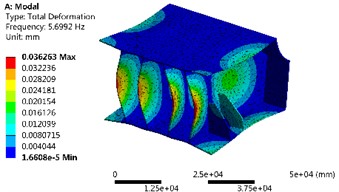
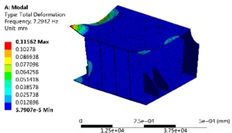
Modal analysis can obtain the natural frequency [9] and mode shape [10] of the cast steel parts, which is convenient for the setting of the vibration exciter. In this paper, the finite element software ANSYS is selected for simulation and calculation. After the model is established, it is imported into the modal analysis module in iges format to start the material parameter setting and grid generation. In finite element analysis, the quality of mesh generation is directly related to the accuracy of calculation results. Generally, the smaller the mesh size, the smaller the deformation of the element, the higher the accuracy of the simulation results, and the longer the calculation time [11]. Since the bottom of the steel casting is in flexible contact during vibration treatment, the simulation type is set to free mode. According to the overall size of the part, the cell size is selected as 10 mm, and the number of elements after local refinement is 210883. Through simulation analysis, the first six order mode shape can be obtained as shown in Fig. 3. It can be seen that the overall stiffness of the model is large, and the distribution of the maximum displacement is symmetrical.
3.2. Natural frequency test
The vibration exciter is usually installed at the end and corner of the workpiece. The installation position shall be smooth and hard. The requirement for the plane is that if the actuator is fixed on the workpiece, if it is uneven, the eccentric part of the actuator may be deformed during vibration, which may cause heating and damage to the bearing. The requirement for rigidity is that if the mounting point is not rigid enough, the actuator itself may vibrate, that is, the vibration of the actuator itself is very large, but the vibration source generated by the actuator will not be transmitted to other parts of the workpiece. The acceleration sensor is used together with the mounting magnetic base, which is adsorbed on the workpiece surface. The sensor is generally installed at the place where the workpiece is far away from the large amplitude (wave crest) exciter. Two points should be paid attention to in the selection of acceleration sensor, including resolution and directivity. The mounting surface of the acceleration sensor shall be perpendicular to the vibration direction, otherwise the vibration cannot be detected; Secondly, the sensor should be installed at a place far away from the actuator and with large amplitude, that is, the peak of the resonant wave. If it is installed at a place with small amplitude, that is, at the wave trough, it is possible to miss the resonance frequency when finding the resonance point.
Fig. 3The first six order mode shape
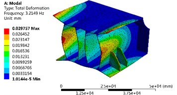
a) 1st order mode shape
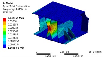
b) 2nd order mode shape
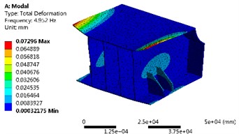
c) 3rd order mode shape
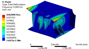
d) 4th order mode shape
e) 5th order mode shape
f) 6th order mode shape
The comparison results of natural frequency simulation and test are shown in Table 1. It can be seen that the simulation results have high accuracy, and the residual stress has little influence on the natural frequency itself. With the increase of modal frequency, the number of resonance peaks of steel castings increases, and the deformation becomes more complex. This shows that the area of components involved in resonance increases, which is more conducive to the adjustment and homogenization of residual stress in this area. In addition, the peak strain also increases, that is, the dynamic stress increases with the release of the vibration stress, and it is easier to reach the yield limit when the component is plastic deformed by superposing with its own residual stress.
Table 1The comparison results of natural frequency simulation and test
Modal order | Simulation value / Hz | Test value / Hz |
1 | 3.21 | 3.26 |
2 | 4.12 | 4.33 |
3 | 4.95 | 5.12 |
4 | 5.34 | 5.39 |
5 | 5.70 | 5.98 |
6 | 7.29 | 7.44 |
4. Influence of exciting vibration on mechanical properties
4.1. Effect on residual stress
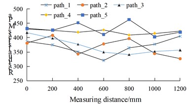
In order to verify the effect of excitation vibration on residual stress, including excitation frequency and impact force amplitude, five detection paths as shown in Fig. 4 are set according to the finite element simulation results of modal shapes. These five paths can effectively represent the residual stress distribution in different directions. All the sensors shall be installed and set at an equal distance of 200 mm along different paths synchronously, then the peak change of residual stress at room temperature can be obtained as shown in Fig. 5. It can be seen that the maximum residual stress of the cast steel parts without vibration treatment is 452 MPa, which is mainly located at the contact position between the end face and the rib, especially in path_4 and path_5.
Fig. 4Setting of residual stress detection path
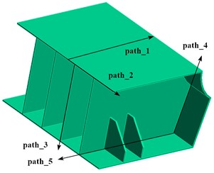
Fig. 5Distribution law of residual stress without excitation
Because the symmetrical steel casting is fixed on the fixture of the vibration platform, vibration sensors should be installed in appropriate component positions to ensure the efficiency and comprehensiveness of the experiment. In order to ensure the consistency of test parameters, 9 samples under the same process conditions were prepared on the upper production line of the same steel casting for testing under different excitation frequencies and forces. In addition, it is necessary to ensure that the temperature (750 ℃) of the cast steel is consistent under the initial test conditions. The excitation treatment time of each sample is set as 60 s, and then the residual stress should be tested after it is naturally cooled to room temperature in air.
4.1.1. Test under different excitation frequencies
Because the residual stress in the directions of path_4 and path_5 is larger and changes more obviously, so it is taken as the verification target. According to the test requirements, the vibration is excited at six tested resonant frequencies as show in Table 1, and the impact force amplitude is set to 150 N. According to the results of the data acquisition system, the residual stress results under different excitation frequencies can be obtained, as shown in Fig. 6. It can be seen that the vibration under different excitation frequencies can effectively reduce the residual stress, although the time for exciting vibration processing is only 60 s. In the direction of path_4, the stress improvement effect is most obvious at the fifth and sixth resonant frequency. In the direction of path_5, the effect is better at the fifth resonant frequency. It can be inferred that the increase of excitation frequency does not correspond to the elimination effect of residual stress, and the effective excitation frequency required in different directions is different. The dynamic vibration characteristics of the specimen can be obtained through modal analysis, and the specimen shows different response modes for different natural frequencies. When the excitation frequency is close to the natural frequency, the test piece will have resonance, thus generating greater excitation displacement under the same excitation, that is, obtaining greater dynamic stress. Therefore, the appropriate excitation frequency is more conducive to the release of residual stress.
Fig. 6Distribution law of residual stress under different excitation frequencies
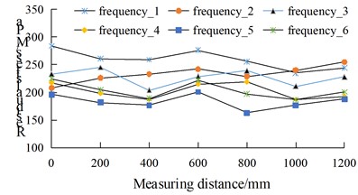
a) Detection direction of path_4
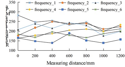
b) Detection direction of path_5
4.2. Test under different excitation force
The exciting force is a cyclic load, which is provided by the circular motion of the eccentric wheel in the exciter. The exciting force can be adjusted by controlling the eccentricity and speed of the motor, and the exciting frequency can be set according to the speed. In the practical application of VSR (Microcomputer Controlled Vibration), when the excitation frequency is determined, the excitation force can be simply controlled by adjusting the eccentricity of the eccentric wheel. According to the results of frequency influence analysis, the best excitation frequency is set as the fifth natural frequency. The residual stress shall be tested under the excitation force of 50 N (force_1), 150 N (force_2) and 250 N (force_3) respectively, and the residual stress results under different excitation frequencies can be obtained, as shown in Fig. 7.
Fig. 7Distribution law of residual stress under different excitation force
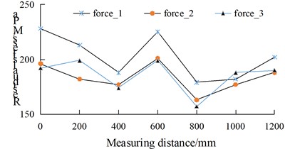
a) Detection direction of path_4
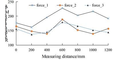
b) Detection direction of path_5
For the excitation test, the shaking table and the test piece can be considered as a whole. The exciting force acts on the whole, generating cyclic dynamic stress in the sample, superposing with the residual stress in the material to reach the local micro yield strength of the sample, so as to produce plastic deformation, stress relaxation and aging effect. Therefore, in a certain range, the greater the excitation force, the more the residual stress can be adjusted and reduced. However, excessive dynamic stress is easy to cause fatigue damage, secondary stress and other adverse effects on the specimen, while too small dynamic stress has no obvious weakening effect on residual stress. According to the test results, the selected 150 N excitation force is the most appropriate.
4.3. Effect on microstructure and strength
At the junction of path_4 and path_5, the metallographic samples were cut and prepared, and the results of the influence of excitation vibration on the microstructure were obtained, as shown in Fig. 8. It can be seen that the grains after vibration treatment are finer. This is because under the action of high temperature excitation and vibration, the transformation rate of austenite increases, the grain boundary area in unit volume increases, and the nucleation rate in the process of austenite decomposition increases, which reduces the stability of austenite. Because the original structure of as cast is uneven and there is composition segregation, the structure and composition become uniform after vibration treatment. Therefore, under the same heating conditions, the austenite formed in the cast steel is very uneven, while the austenite formed by vibration is relatively uniform, and the uneven austenite is decomposed. In the excitation process, if the external stress and concentrated stress formed by the dislocation accumulation group and superposition are greater than the critical shear stress of the metal, the dislocation accumulation group can be opened, the metal will undergo micro plastic deformation, and the residual stress can be released. Therefore, this is also the main reason why the residual stress is significantly reduced.
Fig. 8Microstructure morphology under electron microscope
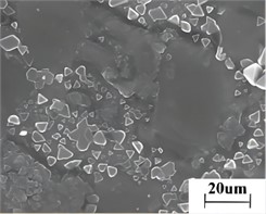
a) Microstructure without excitation
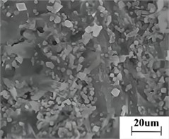
b) Microstructure with excitation (150 N, 5.98 Hz)
Hardness and strength are the key indicators to measure the mechanical properties of mechanical materials. For the study of hardness, in order to ensure the test accuracy, indentation method is used in this paper. Trace method is a micro loss detection method, which requires less sample size and working conditions in the test process. Especially for microhardness test, it is easy to conduct multi-point automatic test. With the average value as the evaluation value, the test results are more reliable. The influence of excitation vibration on residual stress has been studied and proved in this paper. In order to further verify the correlation between residual stress and hardness, the specimen with intermediate thickness is used for testing in a microhardness tester, and the indentation results are shown in Fig. 9. It can be seen that the indentation size of the sample after being excited and vibrated decreases, so its hardness decreases to a certain extent. The samples with different excitation frequencies and impact forces are tested separately, and the hardness comparison results are shown in Table 2. It can be seen that no matter what the excitation frequency and force are, the internal hardness of the cast steel has a downward trend, with the maximum proportion of 9 %.
For strength test, tensile test equipment is used to test the yield strength and tensile strength of cast steel parts. The strength under different test conditions is also shown in Table 2. It can be seen that the influence of different excitation frequencies on the strength is obviously different. For example, when the excitation frequencies are 5.98 Hz and 7.44 Hz, the yield strength and tensile strength are significantly improved. However, under other excitation frequencies, the yield strength did not change significantly or decreased slightly, while the tensile strength increased significantly. Due to the effective reduction of grain size by exciting vibration, fine grain metals have higher strength than coarse grain metals. This is because the strength and other properties of the crystal interface are higher than the grain. The plastic deformation of fine grains caused by external forces can be dispersed in more grains. The plastic deformation is more uniform and the stress concentration is less. In addition, the finer the grains are, the more the crystal interface is, and the larger the area is. The more tortuous the crystal interface is, the more detrimental to the crack growth.
Fig. 9Indentation morphology under microhardness tester
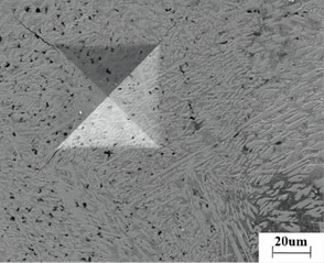
a) Indentation without excitation
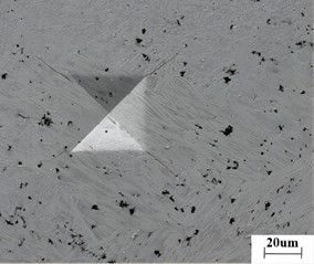
b) Indentation with excitation (150 N, 5.98 Hz)
Table 2Comparison results of hardness and strength under different test conditions
Excitation frequency / Hz | Excitation force / N | Microhardness / HV | Yield strength / MPa | Tensile strength / MPa |
0 | 0 | 556 | 662 | 752 |
3.26 | 150 | 543 | 654 | 761 |
4.33 | 150 | 526 | 647 | 766 |
5.12 | 150 | 553 | 633 | 759 |
5.39 | 150 | 516 | 654 | 783 |
5.98 | 150 | 535 | 688 | 776 |
7.44 | 150 | 526 | 667 | 765 |
5.98 | 50 | 506 | 672 | 733 |
5.98 | 250 | 549 | 669 | 799 |
5. Influence of exciting vibration on stress corrosion resistance
5.1. Stress corrosion cracking test
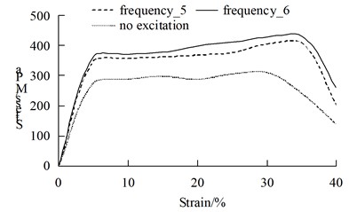
Due to high internal stress, steel castings are prone to stress corrosion in weak acid environment. In order to verify the effect of excitation on stress corrosion, constant load test method was used to test tensile cracks. The test equipment for stress corrosion cracking is shown in Fig. 10, which can provide corrosion medium or environment. In this paper, 0.03 mol/L carbonic acid solution is used. The photo in Fig. 10 was taken by the author in vibration laboratory of Qingdao Huanghai University on December 18, 2022. This stress loading method is usually used to simulate the working stress or external stress that engineering components may be subjected to. The stress corrosion cracking test under constant load can be conducted by direct tensile loading or loading bending specimens. Although the load of the dead load method is constant, due to corrosion and cracks during exposure, the cross section of the specimen decreases continuously, so the effective stress on the fracture surface increases continuously. Compared with the constant deformation test, this will inevitably lead to faster fracture of the sample. Therefore, the dead load test conditions are stricter, the sample life is shorter, and the critical stress of SCC (stress corrosion cracking) is lower. The simplest method of direct tensile loading is to fix one end of the sample and hang the weight directly on the other end. For high-strength metal materials with large sections, a lever system can be used for loading. Small section specimens are mainly used for laboratory tests. Compared with large section specimens, it has the advantages of being more sensitive to SCC initiation, faster test results and easier test operation. As the fifth and sixth order excitation frequencies with 150 N excitation force have better effect on residual stress elimination, the results of stress corrosion fracture test between these two samples and those without vibration treatment are shown in Fig. 11. It can be seen that the yield strength under acidic conditions is smaller, and the specimen under excitation vibration can more effectively resist stress corrosion. The local high tensile stress in the stressed structure is often the origin of cracking. When the material is under the action of tensile stress and in contact with corrosive media, under this condition, the material often cracks after a certain period of use, and extends to the whole section to damage.
Fig. 10Equipment for stress corrosion test
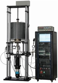
Fig. 11Tensile stress curve
5.2. Fracture mechanics test
Fracture mechanics test is an important way of stress corrosion testing [12]. The fracture test is different from the stress corrosion cracking test, which requires the use of specimens with prefabricated cracks. Generally, the notch is machined on the smooth specimen by mechanical method, and then cracks are generated at the root of the notch by fatigue load or mechanical penetration method. Then apply a certain load on the sample and put it into the environment for testing. By using pre cracked samples and applying linear elastic fracture mechanics to stress corrosion tests, the critical stress field intensity factor and crack growth rate of metal materials in specific media can be determined, and the maximum allowable defect size and service life of components can be determined. The advantages of fracture mechanics method are simple test and short test period. The stress state at the crack tip can be accurately determined by testing. Precracked specimens used in fracture mechanics provide the necessary dielectric electrochemical conditions conducive to crack development, thereby shortening the incubation period. After the sample is prepared, it is placed in the acid environment for 12 hours, and then the impact fracture test is carried out according to the standard. The relevant parameters of the impact toughness are shown in Table 3. It can be seen that only appropriate residual stress can improve the impact toughness, but for high stress parts, due to the brittleness and low strength, it is not conducive to the improvement of toughness and molding.
Table 3Test results of impact toughness
Excitation frequency / Hz | Percentage elongation / % | Impact toughness / kJ/m2 |
0 | 15 | 611 |
5.98 | 21 | 789 |
7.44 | 19 | 766 |
After the impact toughness test is completed, the sample after impact fracture is placed in the scanning electric mirror, so that the micromorphology as shown in Fig. 12 is obtained. It can be seen that the fracture morphology of the three samples has certain similarity, but the number of pits (micro pits) is significantly different. At the excitation frequency of 6, there are many white bumps around the pits of the sample, which are called tear bumps. The formation of pits involves the formation, growth and connection of micropores. Each pit contains second phase particles or crushed inclusions or inclusion particles. They are the core of micropore formation. Under the action of the loading force, the initial crack extends along the tensile direction, forming a cavity (crack growth stage). When there is no exciting vibration, the macro fracture of the sample is more flat, the elongation is relatively low, and there is transgranular fracture phenomenon. Generally, cracks extend along certain crystal planes or slip planes and twin planes to destroy materials. Intergranular (grain boundary) fracture is usually a brittle fracture, in which the crack propagates along the grain boundary. Generally, the grain boundary will not crack. It can be proved that exciting vibration can effectively improve the impact toughness under acidic conditions, and effectively improve the stress corrosion problem.
Fig. 12Comparison of fracture micro morphology
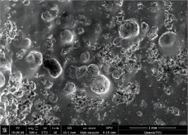
a) No excitation
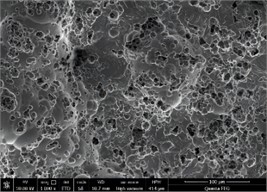
b) Frequency_5
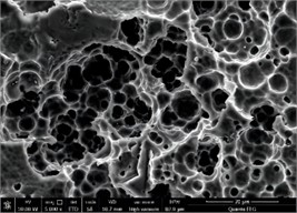
c) Frequency_6
6. Conclusions
Numerical simulation and experimental test are comprehensively used in this paper to study the vibration excitation effect of cast steel parts. It can be known that after vibration treatment, the maximum reduction rate of residual stress peak value in the residual stress detection area of cast steel parts is 64.9 %. Therefore, it can be judged that the treatment process of mode wide frequency vibration to eliminate residual stress is effective. When the cast steel parts are vibrated at high temperature, although the surface hardness of the materials decreases slightly, the yield strength and tensile strength increase to a certain extent. Because the residual stress can be eliminated or homogenized after vibration, the fracture toughness of the material is improved (about 10 %), and the ability to place brittle fracture is improved. The finite element simulation of the mode provides a clear direction for the completion of the test. For example, different excitation frequencies and impact force amplitudes have obvious differences in the treatment effect of residual stress. The experimental study shows that when the excitation frequency is 5.98 Hz and the amplitude of excitation force is 150 N, a good improvement effect can be obtained. The selection of excitation frequency is directly related to the structure of the parts, not the higher the better. When the excitation force is too large, it cannot effectively improve the elimination effect of residual stress, but will cause damage to mechanical parts. The exciting vibration treatment can significantly improve the performance of the cast steel parts. In addition, the reduction of residual stress is conducive to stabilizing the dimensional accuracy of the parts. Its role is not only shown in the small change of dimensional accuracy in the long-term use process, but also can stabilize the size of the parts in a short time.
References
-
G. Pluphrach and S. Yamsai, “Estimation of ferrite grain size and mechanical properties of a 22MnVNb6 microalloyed low carbon cast steel,” Periodica Polytechnica Mechanical Engineering, Vol. 62, No. 1, pp. 83–89, Dec. 2017, https://doi.org/10.3311/ppme.11458
-
M. Chen, J. Jiang, L. Li, and Z. Wang, “The effect of the shear flow on columnar crystal growth in an undercooled melt,” Metals, Vol. 12, No. 9, p. 1487, Sep. 2022, https://doi.org/10.3390/met12091487
-
X. Y. Liu, “A faster than real-time heat transfer model for continuous steel casting,” Journal of Materials Research and Technology, Vol. 19, No. 1, pp. 4220–4232, 2022, https://doi.org/10.1016/j.jmrt
-
K. O. Tveito, A. Pakanati, M. M. ’Hamdi, H. Combeau, and M. Založnik, “A simplified three-phase model of equiaxed solidification for the prediction of microstructure and macrosegregation in castings,” Metallurgical and Materials Transactions A, Vol. 49, No. 7, pp. 2778–2794, Jul. 2018, https://doi.org/10.1007/s11661-018-4632-1
-
M. Truschner, A. Janda, S. C. Bodner, A. Keplinger, and G. Mori, “Effect of cold deformation on the stress corrosion cracking resistance of a high-strength stainless steel,” Journal of Materials Science, Vol. 57, No. 43, pp. 20447–20461, Nov. 2022, https://doi.org/10.1007/s10853-022-07866-6
-
W.-Q. Liu and J.-H. Lian, “Stress-state dependence of dynamic strain aging: Thermal hardening and blue brittleness,” International Journal of Minerals, Metallurgy and Materials, Vol. 28, No. 5, pp. 854–866, May 2021, https://doi.org/10.1007/s12613-021-2250-1
-
E. Skołek, K. Szwejkowska, K. Chmielarz, W. A. Świątnicki, D. Myszka, and A. N. Wieczorek, “The microstructure of cast steel subjected to austempering and B-Q&P heat treatment,” Metallurgical and Materials Transactions A, Vol. 53, No. 7, pp. 2544–2560, Jul. 2022, https://doi.org/10.1007/s11661-022-06685-3
-
A. Martin, T. Lecocq, K.-G. Hinzen, T. Camelbeeck, Y. Quinif, and N. Fagel, “Characterizing stalagmites’ eigenfrequencies by combining in situ vibration measurements and finite element modeling based on 3D scans,” Geosciences, Vol. 10, No. 10, p. 418, Oct. 2020, https://doi.org/10.3390/geosciences10100418
-
D. Ahiwale, H. Madake, N. Phadtare, A. Jarande, and D. Jambhale, “Modal analysis of cracked cantilever beam using ANSYS software,” Materials Today: Proceedings, Vol. 56, No. 1, pp. 165–170, 2022, https://doi.org/10.1016/j.matpr.2022.01.055
-
D. R. Rajkumar, K. Santhy, and K. Ramanathan, “Modal analysis of E-glass basalt laminated composite plates based on experimental mechanical properties using FEA,” Journal of Natural Fibers, Vol. 19, No. 5, pp. 1937–1950, May 2022, https://doi.org/10.1080/15440478.2021.1921661
-
M. Mehrenberger, “Recurrence phenomenon for Vlasov-Poisson simulations on regular finite element mesh,” Communications in Computational Physics, Vol. 28, No. 3, pp. 877–901, Jun. 2020, https://doi.org/10.4208/cicp.oa-2019-0022
-
A. Rosenauer et al., “Influence of delta ferrite on the impact toughness of a PH 13-8 Mo maraging steel,” Materials Science and Engineering: A, Vol. 856, No. 1, p. 144024, Oct. 2022, https://doi.org/10.1016/j.msea.2022.144024
Cited by
About this article

The paper is supported by West Coast New Area University President Fund Special Fund Project (XZJJZY02).
The datasets generated during and/or analyzed during the current study are available from the corresponding author on reasonable request.
Ruiying Shao: conceptualization, software, supervision, validation, writing – original draft preparation. Hongjun Han: investigation, project administration, resources. Kunyan Lu: software, methodology. Juan Song: formal analysis, writing – review and editing.
The authors declare that they have no conflict of interest.
