Abstract
Decreasing of natural frequency of the treated structure is the most frequently used empirical effectiveness criteria in vibration stress relief (VSR). However, dependability and reliability of this criteria is still far from sufficient. In this study, a covert negative treatment phenomenon was investigated, i.e. natural frequency of welded structures decreased after VSR but residual stress in one direction increased. Relationship between natural frequency and residual stresses was studied by mathematical deduction and finite element method. “Natural Frequency Function” and “Natural Frequency Surface (NFS)” was proposed to describe that relationship. “Critical Natural Frequency” (CNF) was proposed to depict possible situations after VSR. A quantitative natural frequency criterion for VSR effectiveness estimation was proposed.
1. Introduction
Metals are unevenly heated in welding procedure, which usually cause significant residual stresses in the welded structures. Residual stresses commonly decrease the strength, deteriorate their fatigue performance and corrosion resistance. Therefore, residual stresses relief for welded structures is an essential issue in both academic and industry fields. Vibration stress relief (VSR) of welded structures is a representative beneficial application of vibration. It has been approved by massive experiments as an efficient stress relief method [1].
Natural frequency of structures and residual stresses usually shows a positive correlation, i.e. higher residual stress in the structures causes higher natural frequency, which is named as stress stiffening effect [2]. Therefore, decrease of natural frequency after VSR is usually considered as a sign of successful stress relief. Currently, it is the most popular empirical effectiveness criteria for VSR effectiveness estimation in practice [3-5]. However, quantitative relationship between decrease amplitude of natural frequency and variation of the residual stresses has rarely been investigated, which makes that empirical criteria can only be used to estimate general variation trend of residual stress, but not to indicate detailed variation pattern. It may even lead to improper estimation when residual stresses in two orthogonal directions are taken into account.
Munsi et al. reported an abnormal phenomenon in VSR treatment of a mild steel bar with a weld line [6], i.e. the residual stress parallel to the weld line decreased after VSR but stress in the orthogonal direction increased. Sun et al reported transversal residual stress increase in welded D6AC steel plates [7]. Occurrence of this negative phenomenon is not accidental. In some circumstance of our studies on VSR, similar phenomenon was found. Thus, reliability and dependability of the natural frequency criteria are often doubted because it can hardly be used to indicate or warn of this abnormal treatment result. Uncertainty of that criteria may make the increasing of residual stress covert and has caused doubt on the VSR technology. Therefore, further study on natural frequency criteria is needed.
A model of the relationship between natural frequency and residual stresses was discussed in this study. An improved natural frequency criterion for VSR, i.e. “Critical Natural Frequency” was proposed to indicate decrease of residual stresses in both two directions. Finite element method (FEM) was used to assist the analysis. Effectiveness of this improved criteria was authenticated by VSR treatment of DH 36 steel welded plates, which is a representative low alloy high strength steel for marine engineering.
2. Mathematical deduction of natural frequency function with 2D stress
In the VSR treatment of plate, the vibration is perpendicular to the plate and the residual stresses. Residual stresses are self-balancing in a welded structure in static state, which means integration of both and in the plate is zero. When the structure vibrates in the direction, the residual stress in the and directions produce component force in the direction because bending of the plate. The differential equation for the vibration of the plate is built for the direction. Though the and is self-balancing in the plate, integration of their component force in the direction is not zero. Therefore, vibration characteristics of the plate is affected by the residual stress.
Maximum residual stress usually locates in the weld line centre and areas nearby, whose value is usually positive and very high. Residual stresses decrease sharply in areas far from the weld line. And the value could be negative on the plate edge. The distribution of residual stresses can be depicted by a product of the maximum tensile stress and a distribution pattern function of the stresses. After the VSR treatment, the specific value of the residual stresses may vary, while the general distribution remains basically unchanged. Therefore, as a rational model simplification, the distribution patter of residual stresses is usually kept unchanged in theoretical analysis of the welded plans vibration. The maximum tensile stress is considered as the main factor influencing natural frequency. Therefore, a model plate with pre-loaded axial tensile stress was employed when investigating the influence of residual stresses on the welded plate. The difference between the even pre-loading and the actual residual stress can be compensated in other items in the frequency-stress equations.
For a certain welded structure in a specific assembling condition, an approximate parabolic relation between maximum residual stress and natural frequency is usually tenable, i.e. square of natural frequency is in linear correlation with maximum residual stress. For example, Gao built mathematical models of for several simple-shaped welded plates and reported parabolic formulas in several specific boundary conditions [8]. Similar relation was reported by Dongand Li [9] in their research on casted iron components. This relation can be considered as the preliminary mathematical foundation for evaluating stress decrease by natural frequency. Therefore, this relation in the 2-dimensional condition can be depicted by a following half-empirical function, i.e. “Natural Frequency Function (NFF)”:
where is the order natural frequency, is a constant and is the function of the effects of and .
It is very difficult to determine the exact formation of NFF. Fortunately, according to the polynomial fitting principle, any continuous functions can be fit by a polynomial function made by a sum of limited or unlimited amount of monomials. Since the vibration differential equation for plates is two order, the NFF for the welded plate was preliminarily built as:
where the , , , and are constants. The effects of the plate shape, assembling and materials on the vibration are embodied in these constants.
2.1. Validation of NFF in one-dimension condition
Exact analytic solutions of vibration equations can be obtained in 1 dimensional conditions. Therefore, the Eq. (2) is substituted in a 1-dimensional condition and its validity is authenticated by comparing with the analytic solutions:
In the one-dimension condition, i.e. let 0, the Eq. (2) turns into:
In the classical vibration theory, natural frequency of a one-dimensional beam with pre-loaded stress is depicted by [10]:
where is the order of vibration, is the elastic modulus, is the length of the beam, is the area of the beam section, is the density, is the loading force on a unit area, which equals to , and is the moment of inertia.
Comparing Eqs. (3) and (4), we get:
Thus, all the items in Eq. (3) have clear physical meanings. is the natural frequency of a plate without residual stresses. is the influence of tensile stress and vibration order. Therefore, the formation of Eq. (2) is in accordance with the vibration dynamic mechanics.
Based on this analysis, the general formation of the NFF in a 2-dimensional condition without taking in to account of initial and boundary conditions shall be modified as:
where is the natural frequency at the order vibration, is the 1st order natural frequency in a stress-free condition, , and are constants. This formula contains the effects of stresses in two directions and their joint effects.
2.2. Critical natural frequency
According to the relationship between frequency and stress, natural frequency decreases monotonously along with the decrease of tensile stress in one dimensional tensile stress condition. In two-dimensional tensile stress condition, the relationship between natural frequency and stresses can be depicted by a curved surface. The contour of the surface indicates the possible and corresponding to a certain natural frequency. Each contour meets with the and axis. From a top view of this curve surface, the smaller the nature frequency is, the closer the contour is to the zero point. Therefore, each natural frequency corresponds to a set of stress conditions that fits the Eq. (6). Contours that fit the Eq. (7) are defined as “Natural Frequency Curve” (NFC), indicating all the stress conditions corresponding to a certain natural frequency:
By discussing the variation pattern of the stress conditions corresponding to different natural frequency, it is possible to analysis the relationship between the maximum stress and the variation of natural frequency. Draw the Mises yielding curve and the NFC, , in the same - coordinate system, as shown in the Fig. 1. Define the crossover point of the Mises yielding cure and the , axis as and . All possible stress states for an ideal elastic material shall be contained in the area encircled by the Mises yielding curve. The part of NFC inside the Mises yielding cure is shown by solid lines, and the outside part is shown by dotted line, which is actually non-existent.
The initial stress state of the plate locates at and the initial stress in the two directions are and . In the procedure of VSR, the stress condition varies along the Mises yielding curve. After the VSR, the vibratory dynamic stress was removed, the stress condition moves into the area encircled by the Mises yielding curve. The natural frequency decreases from to and the corresponding NFC comes closer to the zero point. It meets Mises yielding curve at point and , and meets the lines and at point and , respectively. When the stress state locates on the curve segment , residual stresses in both two directions shall decrease comparing with initial state . When the stress state locates on the segment , residual stress in the direction shall decrease, while that in the direction increase. When the stress state locates on the segment , the residual stresses in the direction shall increase, while that in the direction decrease.
When the natural frequency after VSR treatment decreases to a value lower than the , as shown in the Fig. 1, all parts of the NFC locates inside the area encircled by . In this condition, decreasing of residual stresses in both two directions is guaranteed. Thus, a reliable criterion for stress decreasing in both two directions is defined as “Critical Natural Frequency” (CNF):
where is the NFF containing effects of stress, is the initial stress on the direction and is the initial stress on the direction.
When the initial NFC is intersecting with or embedded in the Mises yielding curve, the discussion on the variation of stress state and natural frequency is similar to the analysis above.
Based on the discussion above, it is reasonable to conclude that the residual stress in the welded structures may vary in three patterns along with the decrease of natural frequency:
1. . When the natural frequency decreases in a minimum amplitude, residual stresses may decrease in both two directions, or decrease in one direction and increase in the other.
2. . The residual stresses may decrease in both two directions or only one direction. Increase of stress would not occur.
3. . When the natural frequency decreases significantly, residual stresses in both the two directions decrease.
3. Computational and experimental validation of CNF criteria
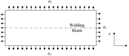
Theoretically, precise simulation of vibration requires the exact self-equilibrium residual stress distribution, which is very difficult to obtain. As a fast simplification with satisfactory accuracy, uniform axial stresses were used to substitute the exact residual stress. Modal analysis was employed to simulate the vibration of the plate. The direction parallel with the weld line is defined as direction, i.e. longitudinal direction, and the perpendicular as , i.e. transversal. The model elements were hexahedron, with 8 nodes. MSC Patran® and Nastran® was used for the simulation. To facilitate discussion about frequency-stress relationship, uniform tensile stresses, and were applied to FEM model to simulate the welding residual stress, as shown in the Fig. 2. The influence of welding residual stresses can be concluded in a function containing a uniform stress. The shape of the weld line cross-section in the model was in accordance with the groove.
Fig. 1Relation between the natural frequency and stress conditions
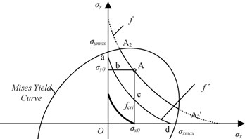
Fig. 2Schematics of the FEM model for the VSR of the rectangle welded structure
To obtain the NFF for the rectangle plate in the 1st order vibration mode, four constants in the Eq. (6) shall be determined, i.e. , , and . Four independent equations shall be established to determine these constants, i.e. four stress states and corresponding natural frequencies shall be obtained to establish the equation set. This can hardly be realized by experiments. FEM was used to determine natural frequencies in four stress conditions. The natural frequency in the maximum stress condition was 70.1 Hz according to the simulation, which is very close to the measured value, i.e. 71.8 Hz. This verified the rationality of the model simplification and the accuracy of FEM simulation.
According to the simulated results, the NFF for the welded plate is:
Fig. 3Natural frequency surface of rectangle structure with tensile stresses
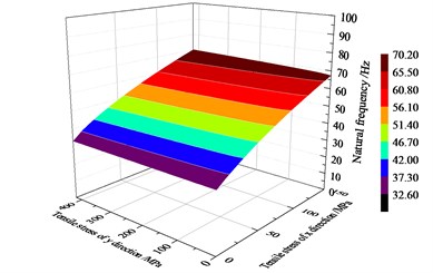
Fig. 3 shows the NFC of the plate in this study. The scale of and is 0-150 MPa and 0-420 MPa, respectively. When 0 MPa, varied from 0 MPa to 420 MPa, the natural frequency varies from 32.7 Hz to 33.2 Hz. When 0 MPa, varied from 0 MPa to 150 MPa, the natural frequency increased from 32.7 Hz to 67.3 Hz. This indicates that the longitudinal stress has a much more significant influence on the vibration natural frequency than the transversal stress . The natural frequency is more sensitive to the stress in the direction parallel to the long side of the plate. According to the calculation, we get 67.3 Hz for the welded plate.
Welded rectangle DH36 plates were treated by VSR to authenticate effectiveness of the improved natural frequency criteria. 14 mm×200 mm×1000 mm DH 36 steel plates were welded by automatic metal inert-gas welding (MIG). In the VSR, the exciter vibrated at 70 Hz for 20 min. 12 welded plates were divided into three groups. One of them was not treated and the other two were treated by VSR at two power levels, i.e. 1 kW and 2 kW.
When the vibration power was 1 kW, In the experiment, maximum longitudinal residual stress, , decreased by ~20 %, while the maximum transversal residual stress, , increased ~13 %. average 1st natural frequency of the plates after the VSR was 69.8 Hz, higher than , corresponding to stress decreasing in one direction and increasing in the other. When the vibration power was 2 kW, the average 1st order natural frequency decreased by ~5.3 Hz, and both the longitudinal and transversal residual stress decreased. The average 1st natural frequency decreased to 66.5 Hz after VSR, lower than . Corresponding measured results indicated residual stress decreasing in both two directions and increasing of residual stress in any directions were not found. Thus, the theoretical analysis met well with the experiments, verifying the validity of the critical natural frequency model.
4. Conclusions
An improved empirical natural frequency criterion for VSR was investigated. Abnormal stress variation after VSR treatment was revealed and discussed. “Natural Frequency Function”, “Natural Frequency Surface” and “Natural Frequency Curve” were defined and used to analysis the variation of natural frequency and stress state after VSR treatment. Further, “Critical Natural Frequency” (CNF) was proposed to estimate the stress state variation after VSR. When the natural frequency after VSR treatment is higher than the CNF, residual stresses may decrease in one direction while increase in the other. When it is lower than the CNF, the residual stresses in both the two directions shall decrease. The CNF criteria was validated by the experimental results and FEM analysis. The technical route proposed in this study provides a quantitative method for fast and reliable effectiveness estimation in VSR treatment and is expected to be widely used in practice.
References
-
Jurcius A., Valiulis A. V., Cernasejus O., Kurzydlowski K. J., Jaskiewicz A. Lech-Grega M. Influence of vibratory stress relief on residual stresses in weldments and mechanical properties of structural steel joint. Journal of Vibroengineering, Vol. 12, Issue 1, 2010, p. 133-141.
-
Su R., Wang B., Ding W., Zhu L. Influence analysis of stress stiffening effect of rotating wheel-disc on its modal characteristics. Journal of Engineering Design, Vol. 16, Issue 4, 2009, p. 292-291.
-
Dawson R., Moffat D. G. Vibratory stress relief: a fundamental study of its effectiveness. Journal of Engineering Materials and Technology, Transactions of the ASME, Vol. 102, Issue 1, 1980, p. 169-176.
-
Vibration Stress Relief Effect-Evaluation Methods. Chinese National Machinery Professional Standard, JB/T5926-2005.
-
Chu J. Y., Chen L. G., Ni C. Z. Comparison of several methods for evaluating effectiveness of vibration stress relief process. Transactions of the China Welding Institution, Vol. 24, Issue 1, 2003, p. 57-60.
-
Munsi A. S. M. Y., Waddell A. J., Walker C. A. The effect of vibratory stress on the welding microstructure and residual stress distribution. Proceedings of the Institution of Mechanical Engineers Part L: Journal of Materials Design and Applications, Vol. 215, Issue 2, 2001, p. 99-111.
-
Sun M. C., Sun Y. H., Wang R. K. Vibratory stress relieving of welded sheet steels of low alloy high strength steel. Mater Letters, Vol. 58, Issue 7, 2004, p. 1396-1399.
-
Gao Y., Tang G., Wan W. Natural frequencies calculation of a quadrate thin plate with welding residual stress. Journal of Vibration and Shock, Vol. 33, Issue 9, 2014, p. 165-167.
-
Dong X., Ren D., Wang D., Zhai Y. Effect of residual stress in ductile iron component on its natural frequency. Advanced Materials Research, Vol. 308, Issue 310, 2011, p. 967-72.
-
Rao S. S. Mechanical Vibration. 4nd Edition, Tsinghua University Press, Beijing, 2009.
About this article

This research is supported by the Changzhou Vocational Institute of Engineering Research Funding (Nos. 11130100116005 and 11130900116003), and Topnotch Academic Programs Project of Jiangsu Higher Education Institutions, TAPP, (No. PPZY2015C235).
