Abstract
The current process of vibratory stress relief is limited by centrifugal force produced by eccentric motor since the excitation frequency is mostly less than 200 Hz. The workpiece with high structural stiffness cannot generate enough dynamic stress by the traditional method. In the present work, the vibratory residual stress using pure lateral resonance and the theory of coupled lateral-torsional resonance are compared by the finite element method. Due to the interaction between lateral vibration and torsional vibration, the torsional vibration generated by external lateral excitation can induce coupled lateral-torsional resonance. The large enough dynamic stress is obtained to reduce the residual stress. The principle to reduce residual stress is analyzed by the Unified strength theory. Numeric solutions are obtained to describe the parametric condition to design the device of vibratory stress relief using coupled lateral-torsional resonance. The operating principle of the related device is introduced.
1. Introduction
Vibratory stress relief (VSR) is an effective method to reduce the residual stress compared with the natural aging and thermal stress relief. It has the advantages of low energy consumption and dramatic reduction of pollution. It can prevent from the oxidation and cracking during thermal treatment. It also can prevent from creating new stress during thermal treatment. There are many VSR devices designed to reduce the residual stress in recent years. Vardanjani M. J., Ghayour M., Homami R. M. [1] set up an experiment to relieve the residual stress of a beam. The beam is clamped by a tool holder and an eccentric cam-like part is coupled to spindle by the chuck use. The rotating spindle forces the cam to produce cycle load, which is applied to the beam. Jia-Siang Wang, Chih-Chun Hsieh, Hsuan-Han Lai, et al. [2] designed a simple cantilever beam vibration system to study the relaxation of residual stress. Both the simple cantilever beam and vibration motor were mounted on a vibration platform. Lv T., Zhang Y. [3] designed a vibration platform to generate the desired dynamic stress for the reduction of residual stress. The small workpieces are not suitable to be treated directly with the eccentric mass motor because they are too small to be clamped. A. Jurčius, A. V. Valiulis, O. Černašejus, et al. [4] clamped the eccentric mass motor to the workpiece directly. The dynamic stress was calculated by the finite element method. Despite many studies about vibration treatment have been done for decades, the application scope has been limited and enormous potential has not yet been tapped. The most important reason is that the lowest natural frequencies of many workpieces are much higher than the frequency produced by a current exciter of VSR equipment. The workpiece cannot produce resonance and create enough dynamic stress.
Several mill rollers are fixed on the platform and shake together with the exciter, as shown in references [5, 6]. Due to the excitation frequency of vibration exciter is still much lower than the natural frequency of the workpiece with high stiffness, the workpiece is difficult to produce resonance and create enough elastic deformation. Though the overall assembly can produce resonance at a low frequency excitation since the overall stiffness of the workpiece and platform is low, the high stiffness workpieces will not produce elastic deformation. They are only in the form of rigid-body motions with the overall structure, without elastic deformation. Improper methods may have been adopted in the engineering practice due to the inadequate understanding of mechanical vibration.
Lihai Wang [7] introduced a VSR method using the spectral harmonic to reduce the workpiece with high stiffness. He alleged that the spectral analyzer can find the several proper vibration mode of the workpiece, but the excitation is still supplied by the traditional vibration exciter, which excitation frequency (50 Hz) is far from 200 Hz. According to the vibration theory, this method may not achieve the reduction of the residual stress since elastic deformation will not be generated in a high stiffness workpiece under low frequency excitation. The dynamic stresses are combined with residual stresses, may exceed the yield strength of the material, and induce local plastic deformation and relaxation of residual stresses [8]. This principle has been widely accepted all over the world. In order to reduce the residual stress by the VSR, enough dynamic stress should be applied to the workpiece; in order to generate elastic deformation and dynamic stress in the workpiece under resonance, proper amplitude of exciting force and frequency must meet the resonance condition. This is an objective law that cannot be evaded.
Zeng Lingtai, Zhu Shigen, et al. [9] also alleged that they could treat a high stiffness workpiece with the VSR progress. However, the excitation scheme they proposed was the current common vibration system, which excitation frequency is only 88 Hz. The workpiece was low resonance with the natural frequency of 88 Hz. He employed an ordinary concept, i.e. the dynamic magnification factor (DMF) to describe the ratio of dynamic displacement amplitude and static displacement amplitude. However, the input and output frequency of the linear system haven’t been changed, the low frequency excitation is unable to excite the high stiffness workpiece to generate resonance.
To date, according to researches and applications in the world, the problem of VSR for high stiffness workpiece has not been effectively solved. In the engineering practice, there is a large number of high stiffness workpieces which cannot be treated with the VSR. In this case, Ganwei Cai [10] proposed a method to reduce the residual stress of shaft parts with high stiffness by coupled lateral-torsional resonance. Zhang Yong [11] derived the partial differential equations of coupled lateral-torsional vibration and made a conclusion: owing to the mass unbalance, harmonic flexural vibration might result in harmonic torsional vibrations, which frequencies were equal to the sum, difference of the rotation frequency and the flexural vibration frequency; harmonic torsional vibration might also result in harmonic flexural vibrations, which frequencies were equal to the sum, difference of the rotation frequency and torsional vibration frequency; when the rotation frequency equaled the sum or the difference of the natural frequency of flexural vibration and torsional vibration, the coupling flexural-torsional resonance might occur. He indicated that the interaction between flexural vibration and torsional vibration was weak, when the rotation frequency equaled the sum or the difference of the natural frequency of flexural vibration and torsional vibration, if there was an external excitation equal to the flexural/torsional natural frequency, the flexural resonance and torsional resonance would strengthen each other. He verified the related theory by experiment of torsional vibration excitation and hammer excitation. Chengbin He, Yujiong Gu, et al. [12] also concluded that the interaction between lateral vibration and torsional vibration was weak. When the rotation frequency equals the sum or difference of the flexural vibration frequency and torsional vibration frequency, if there is some kind of excitation caused by lateral/torsional vibration, which frequency equals to lateral/torsional natural frequency, the lateral vibration and torsional vibration will strengthen each other, strong resonance response will be created. Hiroyuki Fujiwara, Tadashi Tsuji, et al. [13] derived an equation for the motion of the bending-torsion coupled 2 DOF system, and the coupled resonance was verified by numerical simulations: bending-torsion coupled resonance occurred when the rotational speed was equal to the sum/difference of the bending natural frequency and torsional natural frequency . In addition, confirmation of this resonance phenomenon was shown by an experiment: when the rotor was excited in the horizontal direction at bending natural frequency, large torsional vibration appeared; on the other hand, when the rotor was excited by torsion at torsional natural frequency, large bending vibration appeared.
Theory of coupled lateral-torsional vibration is usually applied to predict the response of unbalance rotor subjected to electrical fault [14], response of crack rotor [15], motion of the rotor_bearing system with nonlinear bearing and damper forces [16], response of the gear engagement [17], et al. The coupled lateral-torsional resonance has the properties of combination resonance, i.e. it has the relation of sum or difference between rotational frequency, lateral natural frequency and torsional natural frequency. It means that lateral resonance and torsional resonance can be easy to occur at a relatively low rotational speed at the same time. Due to the small eccentricity of the rotating system, the coupled vibration may not threaten the operation in engineering unless potential fatigue damage. This provides ideas for the use of this method to reduce residual stresses.
The larger is the amplitude that the vibratory stress relief has, the better is the treatment [18]. Guan Zhuohuai and Cai Ganwei [19] studied the parameters selection of VSR device using bending-torsion coupling. They indicated the amplitude of the coupling resonance is related to the speed of the rotating speed and the torque of the external excitation, when the rotating frequency is equal to the lateral natural frequency and the torsional natural frequency, the maximum amplitude of the coupling resonance occurs when the frequency of the external torque excitation is equal to the torsional natural frequency.
According to the above summary, the coupled lateral-torsional resonance occurs when the rotational frequency is equal to the sum or difference of the lateral natural frequency and the torsional frequency, but the coupled interaction between the lateral vibration and torsional vibration is weak. If there is an external excitation, then the lateral vibration and torsional vibration will strengthen each other. When the external excitation frequency equals to the natural frequency, strong vibration will produce. In this paper, the theory of coupled lateral-torsional resonance is applied to determine the designing parameters of VSR device, numerical solutions of traditional method and the proposed method is compared to indicate operating principle of the proposed VSR device.
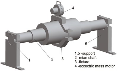
Fig. 1VSR Device using pure lateral resonance
a)

b)
2. VSR device using pure lateral vibration
The shaft workpiece is fixed on the support using the method illustrated in publication [4]. The shaft is divided into 22 elements. Node 1 and node 23 are clamped by a rigid support. The eccentric mass motor is clamped to node 12 by fixture. Point is located at node 15. With the traditional method, the eccentric mass motor should produce an impact force with the frequency equaled to the 1st lateral natural frequency. Fig. 1 shows the VSR Device using pure lateral resonance. Due to the limitation of the eccentric mechanism, the impact frequency of most eccentric mass motor may not exceed 200 Hz. In this case, high frequency excitation method such as ultrasonic vibration should be applied.
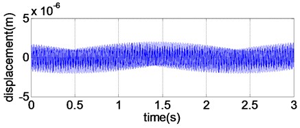
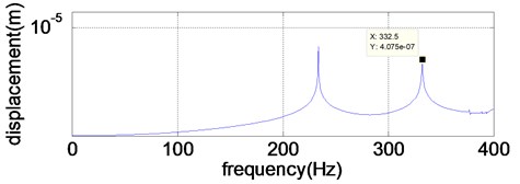
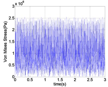
The natural frequency of the main shaft can be calculated by the finite element. Due to all the freedoms of node 1 and node 23 have been fixed, the 1st order lateral natural frequency of the main shaft is up to 332.39 Hz. Set the excitation force and excitation frequency of the eccentric mass motor to be 1000 N and 332.39 Hz, respectively. The displacement response and dynamic stress of point can be plotted in Fig. 2 and Fig. 3, respectively.
As it can be seen from Fig. 2, the peak value of 332.5 Hz is approximately equal to the 1st order lateral natural frequency. Though the shaft is vibrating in the resonance condition, the dynamic stress in Fig. 3 is very small. To produce enough dynamic stress, the excitation should be enlarged, but the restrictive condition cannot be ignored.
Fig. 2Displacement response of pure lateral resonance
a)
b)
Fig. 3Dynamic stress of pure lateral resonance
3. VSR device using coupled lateral-torsional resonance
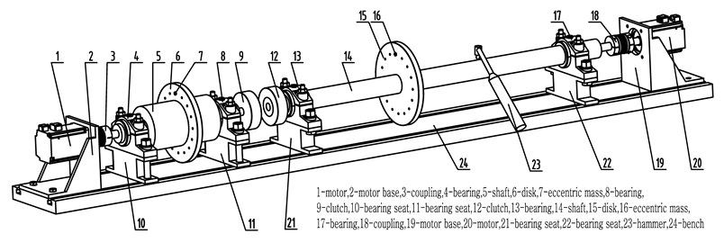
Schematic diagram of VSR device using coupled lateral-torsional resonance is shown in Fig. 4. It consists of the main coupled lateral-torsional resonance system (1-9, 24) and torsional excitation system (12-23, 24). Start the motor 1 and adjust the rotational frequency to make it equal to the difference of the lateral natural frequency and torsional natural frequency of shaft 5, i.e. . Start the motor 20, which rotational frequency is equal to motor 1, adjust the frequency of the impact hammer 23 to produce a torsional vibration, which torsional frequency is equal to the sum of hammer frequency and the rotational frequency of motor 20. The frequency of torsional vibration is created to equal to the torsional natural frequency of shaft 5, i.e. . Connecting clutch 9 and 12, the torsional excitation of shaft 14 is applied to shaft 5 to induce torsional resonance. Due to the coupled characteristic, the torsional resonance and lateral resonance strengthen each other and enough dynamic stress will be generated to reduce the residual stress.
Fig. 4VSR Device using coupled lateral-torsional resonance
4. Parameter conditions of coupled lateral-torsional resonance
The torsional/lateral mode coupling mechanism is related to the eccentricity of the bending and twisting centers along the rotor [20]. Therefore, the characteristic of the unbalance mass should be added to the shaft. When the rotational frequency is equal to the sum or difference of the natural frequency of torsional vibration and lateral natural frequency , the coupled lateral-torsional resonance will occur; if there is an external lateral vibration of , a torsional vibration of will occur, an additional lateral vibration of will be occurred by this , the external flexural vibration will be strengthened by the additional lateral vibration. If there is an external torsional vibration of , a lateral vibration of will occur, an additional torsional vibration of will occur due to this , the external torsional vibration will be strengthened by the additional torsional vibration [21]. To determine the resonance parameters of lateral and torsional coupling, Campbell diagram, i.e. the relationship between rotational speed and natural frequency should be calculated first. Adding the eccentric mass on the disc, setting the rotational frequency of the shaft and applying the external excite force or torque to the shaft, the dynamic stress produced by the coupled lateral-torsional resonance can be used to reduce the residual stress. To induce coupled lateral-torsional resonance easily, the low order lateral and torsional mode should be adopted.
5. Designing of VSR device
5.1. Mathematical model
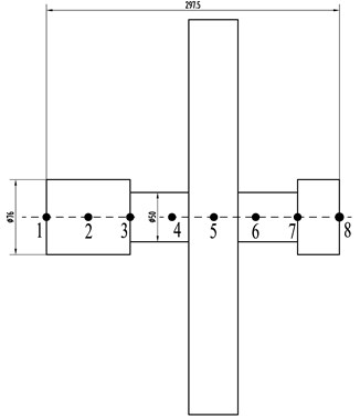
The shaft workpiece supported on bearing as shown in Fig. 5. The natural frequency of the shaft is large due to the high stiffness. Adding an extended shaft coupled to the end of the main shaft, the moment of inertia of the system increases, and the torsional natural frequency decreases [22], as shown in Fig. 6. The yield strength of the steel material is 235 MPa, the density is 7800 kg/m3, elastic modulus is 200 GPa, and Poisson’s ratio is 0.3.
Fig. 5Main VSR rotor-bearing system
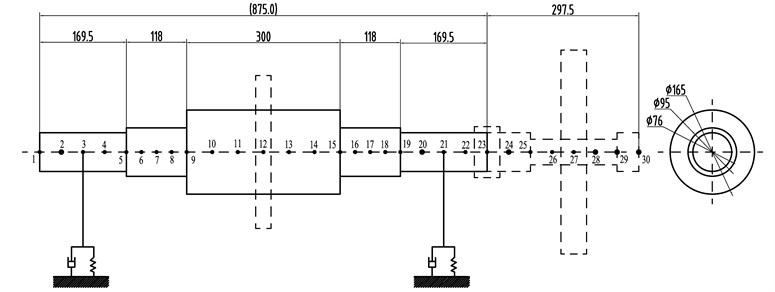
The model of rotor-bearing system is established by the finite element method. The gyroscopic effect and moment of inertia are taken into account. The Multi-Degree-of-Freedom model is more precise than models in [13, 21] and can be analyzed quantitatively. Each node of element has 5 degrees of freedom. The disk and coupling are assumed to be rigid and simplified as a mass point with the gyroscopic effect and moment of inertia. The axial direction of the rotating shaft is -direction; two transverse directions are and -directions. The disk 1 is located at node 12 of the main shaft. The inner diameter is 165 mm, the outer diameter is 350 mm, and the thickness is 30 mm.
The extended shaft is split into 7 elements. The disk 2 is located at node 27, the inner diameter is 50 mm, the outer diameter is 400 mm, and the thickness is 50 mm. The rigid coupling is located at node 23. The motor is connected to node 1. Assuming that the stiffness of the bearing is 1×10⁹ N/m and the damping of the bearing is neglected.
Fig. 6Extended shaft
Assembling the mass matrix and stiffness matrix of the shaft and disc, the gyroscopic matrix and the stiffness coefficient of the bearing by the standard finite element procedure, the system equation of coupled lateral-torsional vibration can be gained:
where is the global displacement vector, , , and are mass matrix, gyroscopic matrix, damping matrix and stiffness matrix, respectively. Force vector consists of unbalance excitation and external excitation. , , and can be seen in references [23, 24]. These matrices can only be used to solve the natural frequency and unbalance response. To solve the transient response of coupled lateral-torsional resonance, the matrix of dynamic eccentric mass needs to be added to the system equation.
Fig. 7Coordination system and deformation configuration
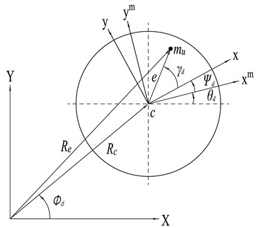
In Fig. 7, - is the inertial reference frame, - is a body coordinate system of the disk-mass which is rotating with the torsionally un-deflected system. - is a body coordinate system of the disk which is attached to the disk and exhibits all its motions. is the angle of rigid-body rotation, is the rotational speed, is the torsional deflection angle, is the mass unbalance, is the distance between and the disk center, and are the components of the vector in - frame. and represent the location of the unbalance mass, and represent the location of the center of the unbalance mass.
The kinetic energy of the dynamic unbalance mass can be expressed as [25]:
Assuming that the torsional deformation is small, , , the global position vector of the mass unbalance can be written as:
where and are the horizontal displacement and vertical displacement of the unbalanced mass at any moment in the - coordinate system, respectively. The derivative of global position vector can be written as:
Substituting Eq. 4 into Eq. 2, the kinetic energy of the dynamic unbalance mass can be written as:
where:
Substituting the kinetic and potential energy expressions into the Lagrange’s equation and writing them in the matrix form, the motion of dynamic unbalance mass can be written as:
where:
and is the generalized coordinate vector of the dynamic unbalance mass.
5.2. Determination of rotational speed
Cangioli, Filippo, et al. [26] employed the Comsol software to calculate the CAMPBELL diagram, plotting the lateral natural frequency and torsional natural frequency over a rotational speed range. In this paper, the related images can be obtained by the numerical analysis. In rotor dynamics, the matrices of system become asymmetric due to the effects of anisotropic bearings and gyroscopic moments, the QR damp method will be used. State vectors are introduced to solve the problem. When solving the natural frequency, the solution of the 2nd order differential equation of motion can be found by rewriting Eq. (1) into a system of 1st order differential equations. By defining a state vector:
Eq. (8) can be written in the state vector form as:
where:
The eigenvalues and eigenvectors of matrix are the corresponding natural frequencies and mode shapes of the rotor-bearing system. Setting a rotational speed range and intervals, the natural frequency of each speed can be obtained, as shown in Fig. 8.
Fig. 8Natural frequency and critical speed
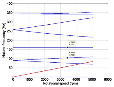
The relationship between the natural frequency and the rotational speed of the rotating shaft can be seen in Fig. 8. Gyroscopic effect causes the forward whirl speed to increase and the backward whirl speed to decrease [27]. The horizontal line in the plot represents the torsional vibration natural frequency [28]. The rotational speed of 3438 rpm corresponds to the rotational frequency of 57.3 Hz. At this rotational speed, the 1st order torsional natural frequency is 161 Hz, and the 1st order lateral natural frequency is 103.8 Hz, as shown in Fig. 8. Frequency 57.3 + 103.8 = 161.1 – 161 Hz meets the coupled lateral-torsional resonance condition. So, the rotational speed of the shaft is set to be 3438 rpm.
5.3. Dynamic response of coupled lateral-torsional resonance
The displacement response is solved by the integration method Newmark- using a MATLAB routine. The mathematical calculation procedure of Newmark- is as follows:
1. Initial calculation:
(1) Compute system matrices , and ;
(2) Initial displacement, velocity and acceleration: , and ;
(3) Choose integration time step 0.001 s, 0.5 and 0.25, the integration constants:
(4) Compute the effective stiffness matrix:
2. For each time step:
(1) Compute the effective force vector at time :
(2) Find the displacement at time:
(3) Find the acceleration and velocity at time:
3. Repeat step 2 for next time step.
Design the rotating shaft of the torsional excitation system, as shown in Fig. 9. The length of the shaft is 560 mm. It is divided into 14 elements. The bearing stiffness is 1×10⁹ N/m, the bearing damping is neglected. The eccentric disc is located at the node 8, the inner diameter is 30 mm, the outside diameter is 200 mm, the thickness is 20 mm, and the motor is connected with the node 15. The material is the same as the shaft in the main VSR rotor-bearing system.
Fig. 9Torsional excitation system
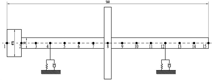
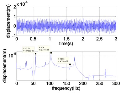
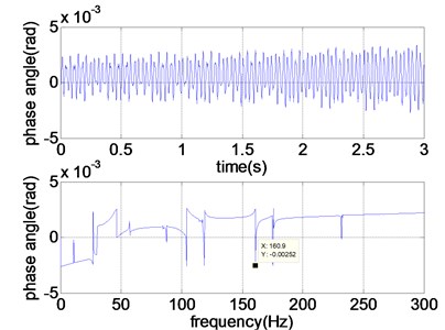
According to the above mentioned definition of lateral-torsional coupling, the hammer excitation can create a torsional vibration, which frequency is equal to the natural frequency of the main VSR rotor-bearing system. The 1st order torsional natural frequency of the main VSR rotor-bearing system is 161 Hz. When the hammer excitation frequency equals the difference of the 1st order torsional natural frequency of the main VSR rotor-bearing system and the rotational frequency, i.e. 161–57.3 = 103.7 Hz, the torsional vibration of 161 Hz will be created. The eccentricity at node 8 of the torsional excitation system is 0.003 kg·m. The rotational frequency of the torsional excitation rotating shaft is equal to the main VSR rotor-bearing system with the same direction of rotation. Applying a hammer excitation to the node 10 of the shaft 14, the hammer force amplitude is 1000 N, and the hammer frequency is 103.7 Hz, the lateral response of node 5 and the torsional vibration response of node 1 can be solved by the transient analysis, as shown in Fig. 10.
As it can be seen from Fig. 10(a), both the rotating frequency and hammering frequency appear. There is a torsional vibration response peak 160.9-161 Hz, as shown in Fig. 10(b). Due to the coupled interaction between lateral vibration and torsional vibration, there is a lateral vibration response peak 161.3 Hz in Fig. 10(a).
The lateral response without hammer excitation of node 5 and the torsional vibration response of node 1 can be seen in Fig. 11(a) and Fig. 11(b).
A comparison between Fig. 10 and Fig. 11 shows that though the rotational speed is equal to the difference of lateral natural frequency and torsional natural frequency, if the hammer excitation is not applied, the torsional vibration response approximately to the 1st order torsional natural frequency (161 Hz) of the main VSR rotor-bearing system will not be produced. So it is necessary to apply the force hammer excitation.
Fig. 10Response of torsional excitation system
a) Lateral response of torsional excitation system
b) Torsional response of torsional excitation system
Fig. 11Response of torsional excitation system (no hammer excitation)
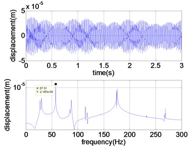
a) Lateral response of torsional excitation system
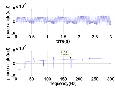
b) Torsional response of torsional excitation system
Fig. 12Response of main VSR rotor-bearing system
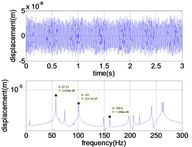
a) Lateral response of main VSR rotor-bearing system
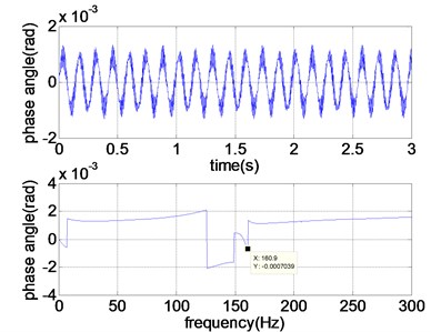
b) Torsional response of main VSR rotor-bearing system
The eccentricity at node 12 of the main VSR rotor-bearing system is 0.006 kg·m. Applying the torsional vibration created by the torsional excite system to node 30 of the main VSR rotor-bearing system and setting the motor output torque to be 70 N/m, the lateral vibration and torsional vibration response of node 15 on the main VSR rotor-bearing system can be solved, as shown in Fig. 12(a) and Fig. 12(b).
The peak frequency 57.31-57.3 Hz in Fig. 12(a) is the rotational speed of the motor. Due to lateral-torsional coupling, the asynchronous lateral vibration 101-103.8 Hz occurs. It is approximately to the 1st order lateral natural frequency, and the 1st order lateral resonance will be excited. Due to the interaction between the torsional vibration and lateral vibration, a lateral vibration response of 160.9-161 Hz approximately equals to the torsional excitation frequency, as shown in Fig. 12(a). As it can be seen from Fig. 12(b), the torsional vibration response of 160.9-161 Hz will induce the 1st torsional resonance. To gain larger amplitude of torsional vibration, the hammer force and eccentric mass should be raised.
5.4. Dynamic stress of coupled lateral-torsional resonance
After solving the displacement response, the strain and stress can be calculated by the geometrical equations and physical equations by MATLAB code [29]. The principal stresses , and can be solved by the stress state of three-dimension stress element. The stress state at a point (element) is determined by the combination of three principal stresses , and . Any complicated stress state may be converted into a twin shear stress state. When the shaft induces lateral and torsional resonance, arbitrary node on the shaft is under complex stress state. Von Mises criterion is the mainly yield criterion for material [30]. Maohong Yu [31] proposed the Unified Strength Theory, which is suitable to analyze the workpiece serviced in complex stress state. He indicated that the Tresca criterion (1864), von Mises criterion (1913), and twin-shear stress criterion (Yu 1961) can be suitable for those materials that have the identical strength both in tension and compression, the shear yield stresses are 0.5 and 0.577 and 0.667 , respectively, where is the shear yield strength and is the uniaxial yield strength of materials. In the present work, the Unified Strength Theory is used to analyze the reduction of the residual stress by coupled lateral-tosional resonance.
Micro plastic deformation leaded to reduction of residual stress is caused by the shear stress [32]. Therefore, the shear stress is the main parameter of the material yield. The twin-shear criterion assumes that the yielding of materials begins when the sum of two larger principal shear stresses reaches the yield limit of the materials [31]:
where, and are three principal shear stresses, respectively.
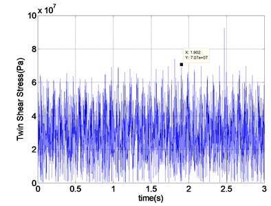
Assuming that the shaft is made of material with the same strength both in tension and in compression ( 0.667 ), the twin-shear stress criterion is chosen. Point is the concentrated area of residual stress, as shown in Fig. 1. According to the analysis above, adding the support bearings and unbalance mass, the twin-shear stress response of the rotating shaft is obtained by the action of torsional excitation and eccentric excitation during 3 seconds, as shown in Fig. 13.
As it can be seen from Fig. 13, there are obvious dynamic stresses occurred at point . They are approximately to 70 MPa. According to the position and the value of the residual stress, enough dynamic stress can be produced by increasing the motor eccentricity and torque amplitude. If there is a torsional excitation motor which can provide alternative torque while rotating, the torsional excitation system shown in Fig. 4 can be replaced to achieve the purpose of coupled lateral-torsion resonance.
Fig. 13Stress response of coupled lateral-torsional resonance
6. Discussion
Comparing the vibration stress relief using pure lateral resonance and coupled lateral-torsional resonance, the dynamic stress produced by the pure lateral resonance is far below the dynamic stress produced by the coupled lateral-torsional resonance. The advantage of VSR using coupled lateral-torsional resonance is that:
1) The natural frequency especially the difference of lateral natural frequency and torsional natural frequency can be adjusted by the extended shaft. The processes of traditional methods are relatively monotonous.
2) Both the lateral resonance and the torsional resonance can be excited by the proposed method. The shaft is subjected to multi-direction excitation. The vibration energy will be transmitted more homogeneous. It is helpful to treat the high stiffness workpiece as per the proposed method.
7. Conclusion
In this paper, the theory of coupled lateral-torsional resonance was applied to a VSR device. Modal analysis and transient analysis were applied as per the finite element method. The paper presents opinions of the operating principle which can be concluded as follows:
1) The natural frequency of the main shaft had been reduced from 332.39 Hz to 103.8 Hz. The designing parameters of VSR device were determined by the characteristics of coupled resonance. The rotational frequency was set to be the difference of lateral natural frequency and torsional natural frequency. Both the rotational frequency (57.3 Hz) and excitation frequency (103.7 Hz) of hammer are less than 200 Hz, which makes the operation easier to be achieved. The proposed method is more flexible to adjust the process for a workpiece with high stiffness. The shaft of torsional excite system should be slender, i.e. the shaft with relatively large aspect ratio. On the one hand, comparing with the shaft with small aspect ratio, greater torsional vibration of shaft with large aspect ratio should be created under the same hammer excitation; on the other hand, shaft with large aspect ratio subjected to hammer excitation should cause less torque loss.
2) The traditional method using pure lateral resonance and the proposed method were compared. The dynamic stress (70.7 MPa) produced by coupled resonance was larger than dynamic stress (2.5 MPa) produced by pure lateral resonance under the same value of excitation force, i.e. 1000 N.
3) The chosen yield criterion depends on the material served in a complex stress state. The Unified Strength Theory contains the Von Mises yield criterion and makes the operation accurate and effective.
References
-
Vardanjani M. J., Ghayour M., Homami R. M. Analysis of the vibrational stress relief for reducing the residual stresses caused by machining. Experimental Techniques, Vol. 40, Issue 2, 2016, p. 705-713.
-
Wang Jia Siang, Hsieh Chih Chun, Lai Hsuan Han, et al. The relationships between residual stress relaxation and texture development in AZ31 Mg alloys via the vibratory stress relief technique. Materials Characterization, Vol. 99, 2015, p. 248-253.
-
Lv T., Zhang Y. Dynamic stress analysis for vibratory stress relief through the vibration platform. IEEE Workshop on Electronics, Computer and Applications, 2014, p. 560-563.
-
Jurčius A., Valiulis A. V., Černašejus O., et al. Influence of vibratory stress relief on residual stresses in weldments and mechanical properties of structural steel joint. Journal of Vibroengineering, Vol. 12, Issue 1, 2010, p. 133-141.
-
Ruan Zhengqing, Yang Lizhi Study on relieving rollers’ residual stress with VSR. China Building Waterproofing, Vol. 6, 2005, p. 28-31.
-
Relieving residual stress technology. http://vsrsuperfinishing.blogspot.com/2013/11/relieving-residual-stress.html
-
Wang Lihai Application of Spectrum Harmonic Aging Replacing Heat Aging on the Motor Manufacturing Process. Master Thesis, Shanghai Jiao Tong University, 2011.
-
Saunders G. G., Claxton R. A. VSR – A Current State-Of-The-Art Appraisal. Residual Stress in Welded Construction and Their Effects. The Welding Institute, London, 1978, p. 173-83.
-
Zeng Lingtai, Zhu Shigen, et al. Influence of vibratory stress relief on residual stress in the surface layer of cast iron roll. Foundry Technology, Vol. 27, Issue 7, 2006, p. 662-664.
-
Cai Ganwei Coupled Flexural-Torsional Resonance VSR Device and its Implementation Method. China Patent, ZL201110101866.5, 2013.
-
Zhang Yong Research on the Torsional and Coupling Flexural-Torsional Vibration of the Turbogenerator Set. Ph.D. Thesis, Tsinghua University, 1997.
-
He Chengbin, Gu Yujiong, et al. Mathematic model of coupling flexural-torsioanl vibration of turbogenerator set shafts. Turbine Technology, Vol. 47, Issue 1, 2005, p. 6-9.
-
Fujiwara Hiroyuki, Tsuji Tadashi, et al. Vibration of bending-torsion coupled resonance in a rotor. ASME International Design Engineering Technical Conferences and Computers and Information in Engineering Conference, 25th Conference on Mechanical Vibration and Noise, Portland, Oregon, USA, 2013.
-
Chengbing H. E., Yujiong G. U., Xing C. Coupled flexural and torsional vibrations analysis of turbine generator shaft systems caused by short circuit fault. Proceedings of the CSEE, Vol. 30, Issue 32, 2010, p. 84-90.
-
Ferfecki P. Study of coupling between bending and torsional vibration of cracked rotor system supported by radial active magnetic bearings. Applied and Computational Mechanics, Vol. 1, Issue 2, 2007, p. 427-436.
-
Jianming Cao, Paul Allaire, Timothy Dimond Coupled lateral and torsional nonlinear transient rotor-bearing system analysis with applications. Journal of Dynamic Systems, Measurement, and Control, Vol. 137, Issue 9, 2015, https://doi.org/10.1115/1.4030612
-
Chen S., Tang J., Zhou C., et al. Modal and whirling analysis of coupled lateral and torsional vibration of herringbone gear. International Journal of Dynamics and Control, Vol. 2, Issue 3, 2014, p. 404-414.
-
Yang Y. P., Jung G., Yancey R. Finite element modeling of vibration stress relief after welding. Proceedings of the 7th Conference on Trends in Welding Research, Callaway Gardens Resort, Pine mountain, Georgia, USA, 2005.
-
Guan Zhuohuai, Cai Ganwei Mechanism of bending-torsion coupling vibration aging and selection of process parameters. Hot Working Technology, Vol. 10, 2016, p. 209-214.
-
Muszynska Agnieszka Rotordynamics. CRC Press, BocaRaton, 2005, p. 161.
-
He Chengbing, Gu Yujiong, et al. Coupled flexural-torsion vibration of rotors with unbalance mass. Proceedings of The Chinese Society for Electrical, Vol. 26, Issue 14, 2006, p. 134-139.
-
Xie Danmei, Liu Zhanhui, et al. A study on the design of turboset shafting torsional vibration expermental models. Turbine Technology, Vol. 47, Issue 3, 2005, p. 199-221.
-
Rao J. S., Shiau T. N., Chang J. R. Theoretical analysis of lateral response due to torsional excitation of geared rotors. Mechanism and Machine Theory, Vol. 33, Issue 6, 1998, p.761-783.
-
Mohiuddin M. A., Khulief Y. A. Coupled bending torsional vibration of rotors using finite element. Journal of Sound and Vibration. Vol. 223, Issue 2, 1999, p. 297-316.
-
Al-Bedoor B. O. Modeling the coupled torsional and bending vibrations of unbalanced rotors. Computer methods in Applied Mechanics and Engineering, Vol. 190, 2001, p. 5999-6008.
-
Filippo Cangioli, et al. An innovative rotordynamical model for coupled flexural-torsional vibrations in rotating machines. Proceedings of the 9th IFToMM International Conference on Rotor Dynamics, Springer International Publishing, 2015, p. 1581-1591.
-
GentaGiancarlo Dynamics of Rotating Systems. Springer, New York, 2005, p. 179.
-
Agostini C. E. Complex modal analysis of a vertical rotor through finite element method. International Research Journal of Engineering Science, Technology and Innovation, Vol. 1, Issue 5, 2012, p. 111-121.
-
Ferreira A. J. M. MATLAB Codes for Finite Element Analysis: Solids and Structures. Springer, New York, 2009.
-
Farajian M. M., Nitschke Pagel D.-T., et al. Mechanisms of residual stress relaxation and redistribution in welded high-strength steel specimens under mechanical loading. Welding in the World, Vol. 54, Issues 11-12, 2010, p. R366-R374.
-
Yu M. H. Unified Strength Theory and Its Applications. Springer, Berlin, Heidelberg, New York, 2004.
-
Munsi A. S. M. Y. Investigation and Validation of Vibratory Methods for Stress Relieving and Weld Conditioning. Ph.D. Thesis, University of Strathclyde, 1999.
Cited by
About this article
This work is supported by the National Natural Science Foundation of China (Grant No. 51365004), Natural Science Foundation of Guangxi, China (Grant No. 2014GXNSFDA118033), Research Project of Department of Education of Guangxi, China (Grant No. 2013ZL002 and 2013ZL003), Project of Science and Technology Bureau of Nanning, China (Grant No. 20144223), Project of Science and Technology Bureau of Yulin, China (Grant No. 201538-2), Project of the Key Laboratory of Modern Design and Advanced Manufacturing of Guangxi Universities ([2014]14).
