Abstract
In this study, the dynamic behaviors of gear system are systematically analyzed with coupled lateral-torsional vibration caused by the gear meshing. A 4-degree-of-freedom (DOF) lumped parameter dynamic model for a spur gear, considering gravity, backlash, eccentricity, transmission errors, external excitation, is proposed. Parametric studies are performed to understand the influence of key parameters such as rotational speed , backlash and error fluctuation on the nonlinear dynamic behavior. The frequency response characteristics of spur gear system show that lateral resonance frequency and torsional resonance frequency simultaneously exhibit in lateral direction. In addition, other nonlinear phenomena including various forms of periodic, quasi-periodic and chaotic vibrations are analyzed. The results show that the nonlinear dynamical behaviors such jump discontinuous phenomena, single-sided impact and double-sided impact are strongly attributed to interaction between backlash, eccentricity and error fluctuant amplitude. Significantly, the appropriate rotational speed and decrease error fluctuant amplitude could effectively control the nonlinear vibration. Whereas the backlash has a complicated effect on the nonlinear dynamical characteristics. The results presented in this paper show that an analysis of the coupled lateral-torsional vibration (CLTV) of the spur transmission gear system. Some research results presented in this paper are useful to dynamic design and vibration control of spur gear transmission system.
1. Introduction
Gear drive systems are one of the most key machine components and are widely used in various applications such as wind turbine, automobile, aircraft, marine vehicle and other industries. Due to the harsh working environment, the loads become more complicated, and also put forward higher requirement on the gear transmission properties. The dynamic behaviors caused by backlash, time-varying stiffness, nonlinear support, random load and etc. have become a main topic of rotating machinery and power transmission system.
In recent decades, many researchers have made a lot of analysis and experiments. Ozguven [1, 2] reviewed the mathematical modelling of the dynamic analysis of gears, which were discussed and a general classification of these models was made. Considering the time-varying mesh stiffness and friction between tooth pairs, Zhang [3] investigated the spur gear system by means of the harmonic balance method. Kahraman [4-5] developed a 3-DOF geared rotor-bearing system including nonlinearities associated with radial clearances in the radial rolling element bearing and backlash. And a criterion used to classify the steady state solutions, and the conditions for chaotic, quasi-periodic and subharmonic steady solutions were determined. Raghothama [6] investigated the periodic motion of a non-linear geared rotor-bearing system by the incremental harmonic balance (IHB) method, and the chaotic motion was investigated by numerical integration. Kubur [7] proposed a dynamic model of a multi-shaft helical gear reduction unit formed by N flexible shafts, and the results of experimental study on a helical gear-shaft-bearing system were also presented for validation of the model. Chen [8] established a 3-DOF dynamic model coupled transverse-torsional motion of a geared rotor-bearing system considering time varying mesh stiffness/damping and bearing stiffness/damping. The effects of contact ratio, bearing stiffness, mesh damping and bearing damping on the dynamic transmission error and vibration stability were investigated. Al-shyyab [9-10] used a non-linear time-varying dynamic model to investigate sub-harmonic and chaotic motions exhibited by a typical multi-mesh gear train. Effects of several system parameters on sub-harmonic motions were described. Kim [11] analyzed the dynamic responses of a pair of spur gears with time-varying pressure angle and the contact ratio. Some dynamic response differences between the new and previous models were demonstrated. Omar [12] presented a 9-DOF model of one stage gear system, which includes varying meshing stiffness and a realistic representation of the gear transmission error (TE) and gear faults. Experimental and simulated data were compared for different operating speeds, torque loads, and gear cracks. Chen [13-14] investigated the effects of the friction and dynamic backlash on the multi-degree of freedom nonlinear dynamic gear transmission system. The results showed that the friction force could enlarge the displacement magnitude and affected the high frequency parts significantly in frequency domain at low speed. Walha [15] investigated the nonlinear dynamic behavior of an automotive clutch coupled with a helical two stage gear system. The effect of this defect on the nonlinear dynamic behavior of the system was investigated. Yang [16] formulated a nonlinear time-varying dynamic model for right-angle gear pair system considering both backlash and asymmetric mesh effects. A set of parametric studies were performed to determine quantitatively the effects of the variation and asymmetry in mesh stiffness and directional rotation radius on the gear dynamic responses. Osman [17] studied the possible interactions between contact fatigue and dynamic tooth loads on gears. The numerical findings compared well with the experimental evidence from a back-to-back test rig, the introduction of profile relief was discussed and its positive influence on the risk of failures at engagement was emphasized. Chen [18] analyzed the spur gear rattle response under the idling condition incorporating the effects of a time-varying and asymmetric mesh stiffness and a backlash nonlinearity, which indicated the idling gear dynamics were relatively insensitive to tooth surface friction. Zhang [19] presented a dynamic model of a multi-shaft helical geared rotor system, the transmission error and gear geometric eccentricity were simulated as excitations. Zhou [20-21] studied an eight-degree-of-freedom nonlinear spur gear-rotor-bearing model with the nonlinear characteristics of gear systems under combined internal and external excitations. And the key parameters were investigated. Han [22] studied the dynamic behaviors of a geared rotor system under time-periodic base motions, the effects of various base angular motions on both frequency response and response spectra were discussed in detail. Li [23-24] investigated the nonlinear dynamic characteristics of a gear pair system with dynamic backlash subjected to internal and external periodic excitations. The IHBM was applied to analyze the frequency response characteristics as well as the effects of dynamic backlash, time-varying stiffness, excitation force amplitude and damping ratio on the dynamic characteristics of the gear pair system. Wang [25] studied the vibration characteristics of a gear rotor system with the pitch deviation, the results showed that the gear mesh stiffness of double teeth meshing area decreases and no load transmission error increased considering the pitch deviation. Ma [26] developed a mesh stiffness model for profile shifted gears with addendum modifications and tooth profile modifications (TPMs). The system vibration responses under different TPM curves were analyzed and the optimum modification curve was further evaluated by amplitude frequency responses. In order to examine the influence of the tooth contact temperature in the meshing surface on the dynamics in the gear system, Gou [27] calculated the flash temperature in tooth surface of a single-stage spur gear system, which indicated the tooth contact temperature had an obvious effect on the dynamics of the gear system. Gao [28-29] studied the nonlinear vibration characteristics of geared rotor bearing system and the interactions among gears, shafts, and plain journal bearings, the dynamic interactions were demonstrated through the analysis of dynamic gear loads and dynamic bearing loads, and the coupling effect behaved different when rolling frequency changed. Hu [30-31] proposed a multi-degree-of-freedom (MDOF) lumped parameter dynamic model considering the coupled translation-rotation vibration and the coupled multi-body dynamics of the face geared rotor system were studied by using the Runge-Kutta numerical method and the effects of mean load and backlash on the dynamic responses were explored.
From the foregoing references above, although existing nonlinear mathematical models used to describe the dynamic behavior of the spur gear are somewhat similar to each other, they differ in terms of the influence of the factors. Backlash, eccentricity, gravity, static transmission errors and external excitation are essential ones that have important influence factors of spur gear dynamic characteristics. Because they have strong nonlinear characters. Besides, gravity is a plays an important role in the system dynamic response compared to excitations from tooth meshing alone. From the above mentioned references, the main difference than previous references in this paper is that the coupled lateral-torsional motions and shaft and bearing vibrations are considered. However, little work has been done to simultaneously characterize the nonlinear effects of gravity, backlash, eccentricity, external excitation and internal excitation. In this research, the proposed 4-DOF lateral-torsional generalized lumped parameter model is capable of predicting more convenient and refined dynamic responses. Besides, due to the harsh working environment, the fluctuation characteristic of input/output torque should be considered in this model. The vibration responses of the gear system and stability analysis are investigated in various cases. Moreover, a comprehensive physical parametric study is accomplished to evaluate the effect of various dynamic parameters such as backlash, eccentricity, external/internal excitation amplitude.
This paper consists four sections. After the introduction, the mathematical model of a spur gear is established, where the gravity, external excitation, static transmission error, backlash and eccentricity are included in Section 2. And the vibration differential equations are derived. In Section 3, the influence of the parameters on the character and level of vibrations are studied. The theoretical predictions are verified with direct numerical simulations by construction of the bifurcation diagrams, 3-D frequency spectrums and tooth impact. Finally, some conclusions are drawn in Section 4.
2. Coupled lateral-torsional vibration model of the spur gear system
2.1. Lumped-parameter model for the spur gear
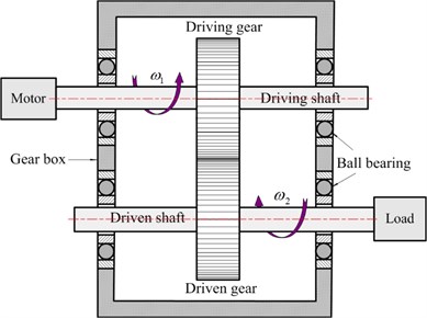
For the purpose of illustration, the simplified 4-DOF lumped parameter model taking into account the coupled lateral-torsional vibration is established in Fig. 1. This line of action is defined as the common tangent line of the base circles in the gears having involute tooth form. All other supports/bearings are also modeled as springs. In addition, friction forces due to gear teeth contact and other dissipative effects are captured using damping. The gear is represented by base circles with radius and , respectively. and indicate the masses of the gears. and represent the moment of inertia of the driving and driven gears. The eccentricities for the gears are denoted by and , respectively. represents the static transmission error, which is the high-frequency caused by manufacturing and installation errors. The gear mesh has a constant backlash equal to 2 along the line of action. and are the centers of driving and driven gears. and represent the center-of-mass coordinates. The torsional angular displacement of gear is assumed to result from a constant angular velocity term (1, 2) plus a small variation displacement due to vibrations originating from the flexibility of the mating gear teeth. Therefore, the angle displacements of the driving and driven gears can be expressed by the following equations:
where and are the constant angular velocity components of the driving and driven gears.
The initial angles of the gears are equal to zero, and the driven gear rotational direction is positive. The centers of mass , and the centers of rotation , can be written:
Fig. 1Dynamic model of coupled lateral-torsional vibration spur gear system
a) Schematic illustration of the coupled system
b) Dynamic model of the coupled system
The meshing process of spur gears is shown in Fig. 1, the dynamic meshing force between driving gear and driven gear is closely related to vibration displacement (bending and torsional vibration) of the gears, which represents by relative coordinates along the line of action. The dynamic meshing force between the driving gear and driven gear is given by:
where, is the backlash function, which is essentially a discontinuous and non-differentiable function, and it is the main source of nonlinearity in the system. So the backlash function is defined by the following equation:
Ignoring the effect of dynamic meshing force caused by the instantaneous variable along the line of action, is the actual deformation, which is the difference between the dynamic transmission error and static transmission error (). Therefore, the is given by:
Submitting Eq. (5) into Eq. (3), the dynamic meshing force is given by:
where, is the static transmission errors, applied along the line of action to model any manufacturing error, installing error, and teeth deformations. As a result, the static transmission error can be approximated as periodic function, and it can be written as follow:
in which, and are the mean and the fluctuation. represents the initial phase angle, then is the mesh angular frequency, and are the driving and driven gear number of teeth, and indicate the rotational speed of the driving and driven gears.
In order to simplify the dynamic problem, the output torque is usually assumed to be constant and neglect the fluctuation in the previous literature. Actually, the output torque also has fluctuation. Therefore, the output/input torque (, ) can be decomposed into mean (, ) and perturbation (, ) parts. This is due to the spur gear is a part of wind turbine gearbox, it essentially fluctuates between low and high values around the stochastic nature of wind speed. Here, the output and input torque, , , are given by:
where, and are the means, and represent the fluctuations, (1, 2) is the rotational frequency, and represent the initial phase angles.
2.2. Equations of the motion
The dynamic equations of coupled gear system, shown in Fig.1, can be described with the four generalized coordinates , , and . After expressing the kinetic energy , the potential energy and dissipation function of the spur gear system in terms of the generalized coordinates, then they are substituted into Lagrange’s equation in order to obtain the vibration differential equations.
The kinetic energy , can be written as follow:
Considering the shaft, the bearing and tooth deformations, the potential energy can be expressed as follow:
Due to take into account the mesh damping, bearing damping and shaft damping, the dissipation function is given by:
The generalized force vector of the spur gear system can be represented by:
The vibration differential equations are derived using equation, which is given by:
Take the coupled effects of lateral vibration and torsional vibration into account, substitution Eqs. (9)-(12) into Eq. (13), the mathematical model of the gear system can be obtained. And a matrix-vector form can be written as:
where, the spur gear system displacement vector is arranged as:
The displacement vector is a 1×4 column vector in which the elements are the generalized coordinates. , (1, 2) are the lateral linear displacement of the driving gear and driven gear. , (1, 2) are the torsional angular displacement of the driving gear and driven gear. , and are the mass matrix, damping matrix and stiffness matrix respectively, is the nonlinear factor vector, and is the linear factor vector are as shown below. It should be noted that the nonlinear internal force vector is a function of the displacement vector , the velocity vector , and eccentricity . The linear factor vector includes the driving torque, load torque, gravity, and the meshing excitations due to gear error:
here, and represent the equivalent bending stiffnesses of shaft and bearing. and are the equivalent torsional stiffnesses of shaft and bearing; and are the equivalent bending damping of shaft and bearing; and indicate the equivalent torsional damping of shaft and bearing.
3. Nonlinear analysis of the coupled system
Eq. (14) describes a strongly nonlinear spur gear system with the gravity, external/internal excitation, static transmission error, backlash, and eccentricity are analyzed using the Newmark method. In order to ensure that the analyzed data related to steady-state conditions, the time series data corresponding to the first sixty percent are deliberately excluded from the dynamical analysis. The conditions and system key parameters are investigated to obtain a basic understanding of the dynamic characteristics for the coupled system. Table 1 summarizes the geometrical and physical parameters of an actual spur gear selected. The effects of rotational speed , backlash and error amplitude on the dynamic responses will be analyzed and discussed in the following sections.
3.1. Model validation
To validate the accuracy of the model in this paper, the vibration responses are shown in figure 2 with the comparison of the reference [32]:
In this section, the two models are analyzed with the same parameters. The related dynamic responses are obtained from the he reference (Fig. 2 (a) and (b)) and the presented model (Fig. 2 (c) and (d)). It can be found that the vibration displacement increases and the fluctuation intensifies in the presented model in this paper, which is caused by the influences of the eccentricity, backlash and coupled external/internal excitation. In addition, the frequency multiplication 2, 3, etc. exist in the presented model. It is clear that the frequencies and amplitudes are different for the two models.
Table 1Main parameters for the spur gear system
Data | Driving/ driven gear | Data | Driving/ driven gear |
Number of teeth | 20 | Torsional stiffness (N.m/rad) | 1.0×10⁷ |
Module (mm) | 8 | Torsional damping (N/(rad/s)) | 4.0×10² |
Radius (m) | 0.3 | Lateral stiffness (N/m) | 1.0×10⁸ |
Mass (kg) | 5.0 | Lateral damping (N/(m/s)) | 5.0×10² |
Moment of inertia (kg.m2) | 0.8 | Error mean (m) | 2.0×10⁻⁵ |
Pressure angle (°) | 20 | Error fluctuation (m) | 3.0×10⁻⁵ |
Meshing stiffness (N/m) | 5.0×10⁸ | Torque mean (N/m) | 300 |
Meshing damping (N/(m/s)) | 1.2×10³ | Torque fluctuation (N/m) | 700 |
Eccentricity (m) | 1.5×10⁻⁵ | Backlash b (m) | 3.0×10⁻⁵ |
Fig. 2Vibration responses of two models a), c) (reference [32]); b), d) (presented model)
![Vibration responses of two models a), c) (reference [32]); b), d) (presented model)](https://static-01.extrica.com/articles/17067/17067-img3.jpg)
According to Fig. 2, it can be seen that the dynamic responses of the presented model in this paper is more realistic than that of the model in reference [32]. As mentioned previously, the main difference is that the model considers coupled lateral-torsional vibration, eccentricity, etc. Throughout the numerical simulation, the influences of different system parameters on the dynamic responses are investigated for the coupled system.
3.2. Analysis of the effect of the rotational speed
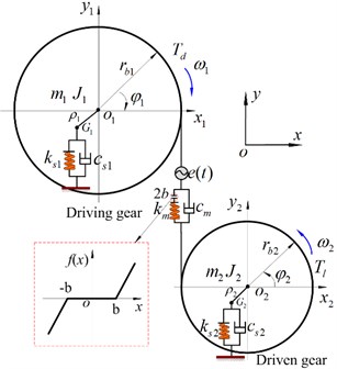
In practical spur gear system, the rotational speed is a commonly used as a control parameter which governs the static positioning of the gears, and other parameters are the same. The dynamic responses of the coupled spur gear system are investigated by using the as a 3-D frequency spectrum and bifurcation diagram control parameter. Fig. 3 and Fig. 4 present the corresponding 3-D frequency spectrum and bifurcation diagram of the vibration system with -direction and direction respectively, which show that the rotational speed has a significant influence on the dynamics of the spur gear system. In this analysis, the parametric excitation is varied in the range of [200, 6000] rad/s. it can be seen from Fig. 3 that the coupled lateral-torsional vibration system displays complex dynamic characteristics with the changing rotational speed. The primary resonance in lateral/torsional direction can be observed. Due to the effect of backlash, the jump discontinuity appears. In addition, the frequency of is the main frequency component, and the amplitude is a nonlinear variation along with the changing rotational speed.
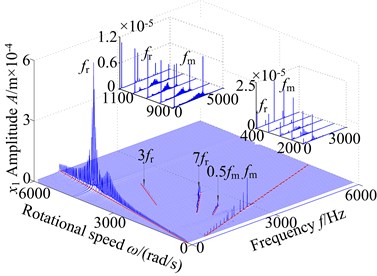
Fig. 33-D frequency spectrum of the coupled system: a) lateral direction, b) torsional direction
a)
b)
Fig. 4Bifurcation diagram using ω as control parameter: a) lateral direction, b) torsional direction
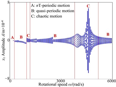
a)
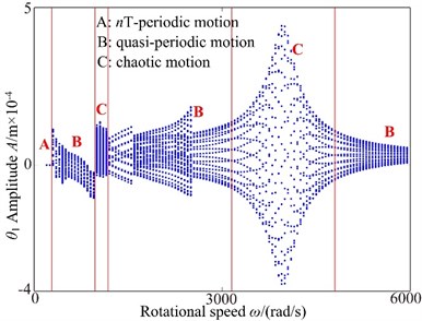
b)
It can be found that the rotational frequency () and meshing frequency () are the predominant components in the interval [200, 400] rad/s. Frequency multiplication (, and is a positive integer) and frequency combination () components display in the corresponding 3-D frequency spectrum. However, the , , , , components obviously exhibit and other discrete frequency components vanish as = 400 rad/s. Due to increased rotational speed, the and are also the dominant frequency components, and the amplitudes increase gradually. Besides, the frequency multiplication and frequency combination components are not obvious. The amplitude of reaches a peak value at = 850 rad/s, and other frequency components are lower than the meshing frequency. Besides, the obvious jump phenomena also appear. However, as is increased from 900 rad/s to 1150 rad/s, the 3-D frequency spectrum performs coupled phenomenon with multiple frequencies, which are concentrated distribution near at 900 rad/s to 1050 rad/s and the multiple frequency components can be obviously found in the 3-D frequency spectrum at 1100 rad/s to 1150 rad/s. With the increasing of the rotational from 1200 rad/s to 3900 rad/s, the is the main frequency component and the amplitude of increases obviously. In torsional direction, the amplitude of reaches a peak value at = 3900 rad/s, which moves backward relative to the torsional primary resonance ( = 31535 Hz), which is caused by nonlinear factors such as backlash, eccentricity and so on. In addition, the 3-rotational frequency and 7-rotational frequency components are contained, but other frequency components are not obvious. In the range of [3900, 4500] rad/s, the 1-rotational frequency amplitude () undergoes a process of decrease first and then increase. The contains a response peak at = 4500 rad/s in addition to a response peak at = 3900 rad/s. which is the lateral primary resonance frequency. By further increasing the rotational speed, the frequency component is simple, the exists only in 3-D frequency spectrum, and amplitude of decreases sharply with obvious jump discontinuous phenomenon.
Fig. 3 (b) presents the 3-D frequency spectrum of the coupled spur gear transmission system in torsional direction using the rotational speed as a parameter. It can be seen from figure that the different dynamic characteristics appear. The torsional primary resonance appears, and the lateral primary resonance cannot be observed. Besides, the and are the dominant frequency components, where the amplitude of decreases gradually, the amplitude of decreases firstly and then increase at < 400 rad/s. Besides, frequency multiplication and frequency combination components appear in the corresponding 3-D frequency spectrum. As the rotational speed is increased further in the range of [500, 850] rad/s, the motion of the vibration system is relatively simple and the and are the main frequency components with different speed. Furthermore, the amplitude of is larger than the amplitude of and other components withdraw obviously. the amplitude of reaches to the peak at = 850 rad/s. As the rotational speed is further increase from = 900 rad/s to = 1050 rad/s, in addition to the and , the continuous frequency components appear in the frequency spectrum. At = 900 rad/s the response amplitude of drops causing an abrupt jump down in the 3-D frequency response. Finally, at higher values of , i.e. ≥ 1100 rad/s, the reaches to peak at = 3900 rad/s, which is the torsional primary resonance, and the peak appears backwards phenomenon. In addition, the (at = 1100 rad/s-2300 rad/s), (at = 1100 rad/s-1500 rad/s) and (at = 1600 rad/s-2400 rad/s) obviously exist in the 3-D frequency spectrum. Analyzing the results of this section, the increases of the rotational speed can decrease the nonlinearity degree of the coupled lateral-torsional spur gear system.
In Fig. 4(a), it can be observed that the spur gear system undergoes periodic motion, quasi-periodic motion to chaotic behavior and then returns to quasi-periodic. As shown in Fig. 4(a), the bifurcation diagram exhibits periodic-1 motion at ≤ 250 rad/s. When increases from 300 rad/s to 850 rad/s, periodic-1 motion is replaced by quasi-periodic motion and performs jump phenomena at = 850 rad/s. By further increasing the rotational speed in the range of [900, 1100] rad/s, the coupled spur gear system exhibits slight chaotic motion, which is a corresponding phenomenon with continuous frequency in 3-D frequency spectrum. As increases , the gear system undergoes quasi-periodic motion and chaotic motion in a rotational speed 1150 rad/s < < 5000 rad/s. However, greater than 5000 rad/s, chaotic motion transits to quasi-periodic motion.
In torsional direction, in the interval [200, 6000] rad/s, it can be found from Fig. 4(b) that the motion of the coupled system undergoes periodic-, quasi-periodic and chaotic motions. When 850 rad/s, 1-periodic motion is replaced by quasi-periodic motion, and occurs jump phenomena at 850 rad/s. When increases from 900 rad/s to 3200 rad/s, the bifurcation diagram shows that the gear system performs chaotic motion transits to -periodic motion and then quasi-periodic motion. At higher values of the 3250 rad/s-6000 rad/s, the dynamical behavior of the spur gear system is found to be chaotic motion and then quasi-periodic motion. From these results, it can be seen that the spur gear system undergoes a different motion as the rotational speed is increased over the range 200 rad/s-6000 rad/s.
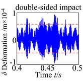
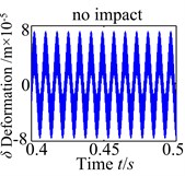
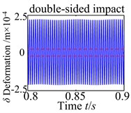
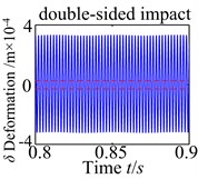
Fig. 5Tooth impact of the spur gear system u with changing ω
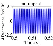
a)850 rad/s
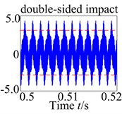
b)3850 rad/s
c)4500 rad/s
d)6000 rad/s
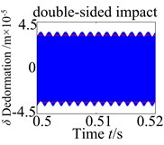
In order to detailedly study the influences of the rotational speed, the tooth impact is examined next. It may be also noted that tooth impact may occur because of the gear backlash nonlinearity. There are three possible types of tooth impact cases: no tooth impact ( and ), single-sided tooth impact ( and or and ) and double-sided tooth impact ( and ). The various case of tooth impacts can be observed in the time history plots at 850 rad/s, 3850 rad/s, 4500 rad/s, and 6000 rad/s, respectively. It can be seen from Fig. 5 that there is obviously no tooth impact at low values of the rotational speed, i.e., 850 rad/s. Furthermore, as rotational speed increase to 3850 rad/s, which is the torsional primary resonance frequency, the double-sided tooth impact can be clearly observed, and it is the dominant response. As expected, the double-sided tooth impact behavior can be seen occurring around the primary resonance for 4500 rad/s. However, when rotational speed is increased to 6000 rad/s, the single-sided tooth impact is the dominant response in the spur gear system. Hence, it can be concluded that the rotational speed has a significant influence on the dynamic behaviors of the coupled lateral-torsional spur gear system.
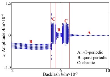
3.3. Analysis of the effect of the backlash
Gear backlash is an important parameter effect on the dynamic behaviors of the gear system and due it has a strong nonlinear character, which may be designed for better lubrication and to reduce interference, or caused by manufacturing and installing errors. Therefore, the influence of backlash on the dynamic responses is very complex. In order to analyze more deeply, the dynamic characteristics of the coupled gear system is investigated using the backlash as a 3-D frequency spectrum and bifurcation control parameter in lateral and torsional directions. A transition from simple motion to complex motion and then simple motion dynamical behaviors will be seen when is increased from 2×10⁻⁵m to 1.0×10⁻⁴m.
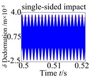
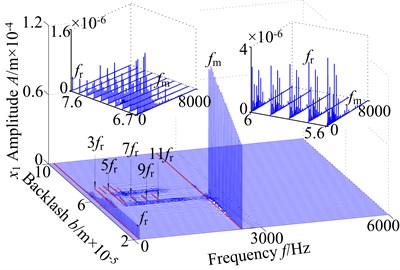
Fig. 63-D frequency spectrum of the coupled system: a) lateral direction, b) torsional direction
a)
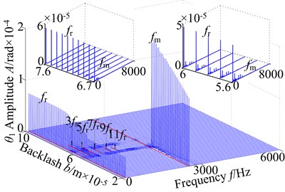
b)
Fig. 6(a) displays the corresponding 3-D frequency spectrum in lateral direction with as control parameter. It can be seen that the and appear simultaneously and the meshing frequency () is the dominant frequency component, which is greater than other components at ≤ 5.0×10⁻⁵ m. Besides, the amplitude if have a peak value = 4.8×10⁻⁵ m, and then the amplitude of exhibits an obvious jump phenomenon at = 5.0×10⁻⁵ m. The frequency multiplication and frequency demultiplication components do not appear. In the range of [5.3×10⁻⁵, 5.6×10⁻⁵] m, the complicated continuous frequency components appear in lateral direction, which indicates that the coupled spur system displays chaotic motion. By further increasing the backlash , the frequency multiplication (, , , , ,) and meshing frequency appear obviously, and the amplitudes decrease gradually in the interval [5.7×10⁻⁵, 6.1×10⁻⁵] m. As the is increased slightly, the coupled gear system displays complicated higher harmonic components at 6.2×10⁻⁵ m < < 7.5×10⁻⁵ m. In addition, the and are the main frequency components. When > 7.6×10⁻⁵ m, the amplitudes of and keep almost unchanged, and other frequency components vanish gradually.
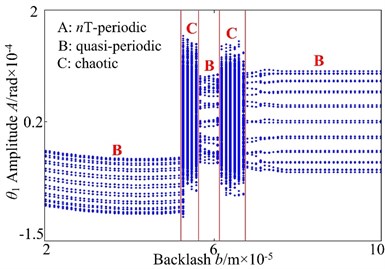
The corresponding 3-D frequency spectrum in torsional direction is shown in Fig. 6(b), it can be found that the amplitudes of and are obvious greater than those in lateral direction. In the range of [2.0×10⁻⁵, 5.0×10⁻⁵] m, the amplitude of is a constant value, and the increases obviously, which reaches the peak value closing to = 4.8×10⁻⁵m. As the backlash is increased in the interval [5.1×10⁻⁵, 7.5×10⁻⁵] m, the coupled system appears continuous frequency components in the range of [5.1×10⁻⁵, 5.7×10⁻⁵] m, though frequency multiplication components (, , , , , ) at 5.7×10⁻⁵ m < < 6.1×10⁻⁵ m, to return to continuous frequency components in the interval of [6.2×10⁻⁵, 7.5×10⁻⁵] m. Finally, in the range of [7.6×10⁻⁵, 10.0×10⁻⁵] m, the is the main frequency component, and the and other frequency components vanish gradually.
Fig. 7Bifurcation diagram using b as control parameter: a) lateral direction, b) torsional direction
a)
b)
Fig. 7(a) presents the bifurcation diagram of the spur gear system using parameter as control parameter. In Fig. 7(a), when backlash is increased, it can identify the system exhibits a sequence of -period motion, quasi-periodic motion and chaotic response. By analyzing the 3-D frequency spectrum, some key points are selected, which indicate spur gear system motions have been changed with increasing backlash . The spur gear system undergoes quasi-periodic motion at low backlash when increases from 2.0×10⁻⁵ m to 5.1×10⁻⁵ m. As increase from 5.2×10⁻⁵ m to 5.5×10⁻⁵ m, the system exhibits chaotic motion through quasi-periodic motion. At higher values of the backlash , the dynamic behavior of the spur gear system is found to be quasi-periodic dynamic behavior at 5.6×10⁻⁵ m-6.1×10⁻⁵ m, and then transits to chaotic motion at 6.2×10⁻⁵ m-6.7×10⁻⁵ m, while the much higher vibration occurs. Finally, 6.8×10⁻⁵ m, the quasi-periodic motion is replaced by -periodic motion.
The bifurcation diagram for the torsional vibration of the driving gear is shown in Fig. 7(b). It is noted that similar behavior is observed by torsional vibration and lateral vibration. In this section, it only presents a simple description for the bifurcation diagram. When backlash increases from 2.0×10⁻⁵ m to 5.1×10⁻⁵ m, it can be noted that the gear shows quasi-periodic motion. When backlash is further increased, it can see the gear system exhibits a sequence of complicated motion state, the dynamic behavior of the system is found to be chaotic motion at 5.2×10⁻⁵ m to 5.5×10⁻⁵ m, quasi-periodic motion at 5.6×10⁻⁵ m to 6.1×10⁻⁵ m, and then the gear system reverts to a chaotic motion once again at 6.2×10⁻⁵ m to 6.7×10⁻⁵ m. However, as is greater than 6.8×10⁻⁵ m, the chaotic motion transits to quasi-periodic motion.
For a better clarity the influence of the backlash , the dynamic behaviors are corresponding with no tooth impact, single-sided tooth impact and double-sided tooth impact as shown in Fig. 8. It investigates four backlash conditions chosen (3.0×10⁻⁵ m, 5.3×10⁻⁵ m, 7.5×10⁻⁵, 10×10-5 m), at the low backlash range (3.0×10⁻⁵ m), the spur gear behaves have no complicated nonlinearity with no evidence of tooth impact. As the increases, the characteristics indicate the influence of strongly backlash nonlinearity causing single-sided tooth impact (5.3×10⁻⁵) and double-sided tooth impact (7.5×10⁻⁵ m), which have no obvious periodicity and the vibration of the system is in the unsteady state. However, as is increased further, the single-sided tooth impact and double-sided tooth impact vanish gradually. The spur gear response changes back to no tooth impact.
Fig. 8Tooth impact of the spur gear system with changing b
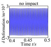
a)3.0×10⁻⁵ m
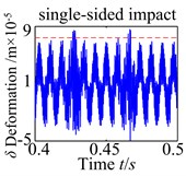
b)5.3×10⁻⁵ m
c)7.5×10⁻⁵ m
d)10×10-5 m
3.4. Analysis of the effect of the error fluctuation
The transmission error caused by manufacturing error and assembly error, which is a displacement excitation and has an important influence of the dynamic response for the coupled system. To illustrate the influence on the spur gear system of the error fluctuant amplitude , a further analysis has been carried out considering several set of simulated of the error fluctuant amplitude. Fig. 8-9 present the 3-D frequency spectrum and bifurcation of the system using as a control parameter, and the values of the other parameters remain unchanged.
Fig. 93-D frequency spectrum using er as control parameter: a) lateral direction, b) torsional direction
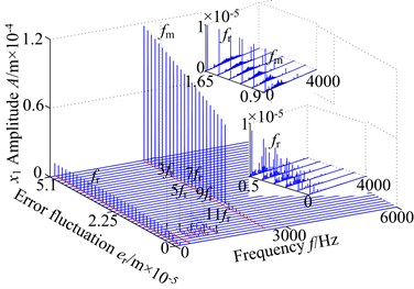
a)
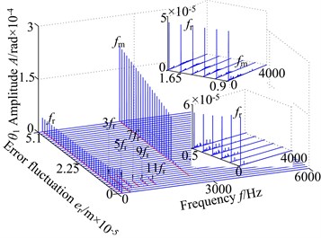
b)
The 3-D frequency spectrum of the coupled gear system in lateral direction with error amplitude is displayed in Fig. 9(a). In a light value of , the rotational frequency , the frequency multiplication (, , , ) and frequency combination () appear in the range of [0, 1.05×10⁻⁵] m. In addition, the amplitude of is the maximum value and other amplitudes are lower than the . Further increase of the error amplitude in the interval [1.2×10⁻⁵, 5.1×10⁻⁵] m, the amplitude of increases gradually, and the amplitude of becomes large and occurs jump phenomenon suddenly with the increasing error amplitude. Besides, the frequency multiplication and frequency combination components vanish obviously.
Fig. 9(b) shows the 3-D frequency spectrum in torsional direction with error amplitude as control parameter in the range of [0, 5.1×10⁻⁵] m. At low error amplitude at < 1.05×10⁻⁵ m, the and the frequency multiplication components are obvious. The amplitude of is not observed. With the increasing of error amplitude, the amplitude of decreases slightly, and the amplitude of presents diametrically opposite nature and the amplitude has an obvious jump discontinuity unexpectedly at = 1.2×10⁻⁵ m. Increasing the error amplitude even further, the amplitude of keeps approximately the same magnitude, and the amplitude of increasing gradually.
Fig. 10Bifurcation diagram using er as control parameter: a) lateral direction, b) torsional direction
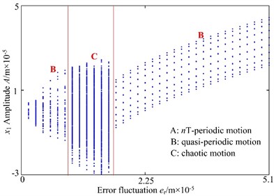
a)
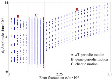
b)
For a better understanding the trend of motion with the error fluctuation, Fig. 10(a) presents the bifurcation diagram using the fluctuation as control parameter in lateral direction. As increases from 0 to 0.9×10⁻⁵ m, the spur gear system presents quasi-periodic motion. However, as is increased from 1.05×10⁻⁵m to 1.8×10⁻⁵ m, the spur gear system exhibits chaotic motion through quasi-periodic motion, which is mainly due to the effect of the backlash. Finally, as the fluctuation is further increased, i.e., 1.95×10⁻⁵ m, the chaotic motion is replaced by quasi-periodic motion.
In torsional direction, the effect of the parameter is illustrated in the bifurcation diagram as shown in Fig. 10(b). It can be observed that the gear system exhibits quasi-periodic motion at low values of the fluctuation, i.e., 0.9×10⁻⁵ m and then the chaotic motion can be found as the fluctuation is increased over 1.05×10⁻⁵ m. At higher values of the fluctuation, i.e., 1.95×10⁻⁵ m, the dynamic behaviors of spur gear show quasi-periodic motion.
Fig. 11Tooth impact of the spur gear system with changing er
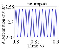
a)0
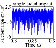
b)1.05×10⁻⁵ m
c)1.8×10⁻⁵ m
d)5.1×10⁻⁵ m
From the results, under different error fluctuation conditions, as show in Fig. 11, the dynamic responses show that no tooth impact, single-sided tooth impact and double-sided tooth impact are demonstrated in the spur gear. There is obviously no tooth impact at lower fluctuation values. As increases to 1.05×10⁻⁵m, this type of characteristic indicates the effect of transmission error fluctuation causing single-sided tooth impact. The tooth impact continues as the fluctuation increases until double-sided tooth impact begins to show up. When increases to 5.1×10⁻⁵m, the double-sided tooth impact behavior remains dominant response. These results implicate that the fluctuation of the transmission error tends to worse the degree of the nonlinearity.
4. Conclusions
The proposed 4-DOF generalized lumped parameter model is established by considering the more realistic situation with backlash, gravity, eccentricity, transmission error and lateral-torsional coupling. Therefore, the model in this paper can produce a more accurate dynamic response than does the previous models. The influences of rotational speed, backlash and error amplitude on the dynamic responses are analyzed. The results of this paper are concluded as follows:
1) The rotational speed is a key parameters affecting the dynamic characteristics of the coupled lateral-torsional spur gear. The amplitude of reaches higher levels closing to natural frequency and the spur gear system undergoes a loss a stability with the increasing rotational speed. In addition, the no tooth impact, single-sided tooth impact, double-sided tooth impact of the coupled lateral-torsional spur gear can be obviously observed in the corresponding 3-D frequency spectrum and bifurcation diagram.
2) Due to exist backlash, the coupled system presents strong nonlinear characteristics. With the increasing of backlash, it can be found that the meshing frequency amplitude increases firstly and then decreases with jump phenomena. The nonlinear dynamical behaviors are corresponding with no tooth impact, single-sided tooth impact, and double-sided tooth impact. Whereas the increase backlash could no longer control the nonlinear dynamical vibration of the spur gear. The error fluctuant amplitude has significant effect on the nonlinear dynamic behaviors and the increases of the error fluctuant amplitude could reinforce the nonlinear vibration of the spur gear system.
3) Furthermore, the results also show that designing a spur gear system to operate at high rotational speed, a large backlash and a large error fluctuant amplitude should be avoided especially when the rotational speed is close to the system’s natural frequencies. Therefore, the conclusion of this paper can confirm the importance of taking the nonlinear factors effect into account when predicting the dynamical behaviors of the practical spur gear system.
References
-
Ozguven H. N., Houser D. R. Mathematical models used in gear dynamics – a review. Journal of Sound and Vibration, Vol. 121, Issue 3, 1988, p. 249-256.
-
Li M., Sun T., Hu H. Y. Review on dynamics of geared rotor-bearing systems. Journal of Vibration Engineering, Vol. 15, Issue 3, 2002, p. 383-411.
-
Zhang S. H., Li Y. P., Qiu D. M. Dynamic analysis of a rotor-bearing system by means of the harmonic balance method. Chinese Journal of Mechanical Engineering, Vol. 36, Issue 7, 2000, p. 18-22.
-
Kahraman A., Singh R. Interactions between time-varying mesh stiffness and clearance non-linearities in a geared system. Journal of Sound and Vibration, Vol. 146, Issue 1, 1991, p. 135-156.
-
Kahraman A., Singh R. Nonlinear dynamics of a geared rotor-bearing system with multiple clearances. Journal of Sound and Vibration, Vol. 144, Issue 3, 1991, p. 469-506.
-
Raghothama A., Narayanan S. Bifurcation and chaos in geared rotor bearing system by incremental harmonic balance method. Journal of Sound and Vibration, Vol. 226, Issue 3, 1999, p. 469-492.
-
Kubur M., Kahraman A., Zini D. M., Kienzle K. Dynamic analysis of a multi-shaft helical gear transmission by finite elements: model and experiment. Journal of Vibration and Acoustics, Vol. 126, 2004, p. 398-40.
-
Chen A. H., Luo S. M., Wang W. M., Guo Y. F., Liu D. S. Numerical investigations on dynamic transmission error and stability of a geared rotor-bearing system. Chinese Journal Mechanical Engineering, Vol. 40, Issue 4, 2004, p. 398-405.
-
Al-shyyab A., Kahraman A. Non-linear dynamic analysis of a multi-mesh gear train using multi-term harmonic balance method: sub-harmonic motions. Journal of Sound and Vibration, Vol. 279, 2005, p. 417-451.
-
Al-shyyab A., Kahraman A. Non-linear dynamic analysis of a multi-mesh gear train using multi-term harmonic balance method: period-one motions. Journal of Sound and Vibration, Vol. 284, 2005, p. 151-172.
-
Kim W., Yoo H. H., Chung J. T. Dynamic analysis for a pair of spur gears with translational motion due to bearing deformation. Journal of Sound and Vibration, Vol. 329, 2010, p. 4409-4421.
-
Omar F. K., Moustafa K. A. F., Emam S. Mathematical modeling of gearbox including defects with experimental verification. Journal of Vibration and Control, Vol. 18, 9, p. 1310-1321.
-
Chen S. Y., Tang J. Y., Luo C. W., Wang Q. B. Nonlinear dynamic characteristics of geared rotor bearing systems with dynamic backlash and friction. Mechanism and Machine Theory, Vol. 46, 2011, p. 466-478.
-
Chen S. Y., Tang J. Y., Chen W. T., Hu Z. H., Gao M. P. Nonlinear dynamic characteristic of a face gear drive with effect of modification. Meccanica, Vol. 49, 2014, p. 1023-1037.
-
Walha L., Driss Y., Khabou M. T., Fakhfakh T., Haddar M. Effects of eccentricity defect on the nonlinear dynamic behavior of the mechanism clutch-helical two stage gear. Mechanism and Machine Theory, Vol. 46, 2011, p. 986-997.
-
Yang J. Y., Peng T., Lim T. C. An enhanced multi-term harmonic balance solution for nonlinear period-one dynamic motions in right-angle gear pairs. Nonlinear Dynamics, Vol. 67, 2012, p. 1053-1065.
-
Osman T., Velex P. H. A model for the simulation of the interactions between dynamic tooth loads and contact fatigue in spur gears. Tribology International, Vol. 46, 2012, p. 84-96.
-
Chen Z. G., Shao Y. M., Lim T. C. Non-linear dynamic simulation of gear response under the idling condition. International Journal of Automotive Technology, Vol. 13, Issue 4, 2012, p. 541-552.
-
Zhang Y. M., Wang Q. B., Ma H., Huang J., Zhao C. Y. Dynamic analysis of three-dimensional helical geared rotor system with geometric eccentricity. Journal of Mechanical Science and Technology, Vol. 27, Issue 11, 2013, p. 3231-3242.
-
Zhou S. H., Song G. Q., Sun M. N., Ren Z. H. Nonlinear dynamic analysis for high speed gear-rotor-bearing system of the large scale wind turbine. Journal of Vibroengineering, Vol. 17, Issue 8, 2015, p. 4560-4574.
-
Zhou S. H., Song G. Q., Ren Z. H., Wen B. C. Nonlinear dynamic analysis of coupled gear-rotor-bearing system with the effect of internal and external excitations. Chinese Journal of Mechanical Engineering, Vol. 29, Issue 2, 2016, p. 289-291.
-
Han Q. K., Chu F. L. Dynamic behaviors of a geared rotor system under time-periodic base angular motions. Mechanism and Machine Theory, Vol. 78, 2014, p. 1-14.
-
Li Y. G., Chen T. N., Wang X. P., et al. Non-linear dynamics of spur gear pair under external periodic excitation. Journal of Xi’an Jiaotong University, Vol. 48, Issue 1, 2014, p. 1-5.
-
Li Y. G., Chen T. N., Wang X. P. A Non-linear dynamics of gear pair with dynamic backlash subjected to combined internal and external periodic excitations. Journal of Vibration and Control, Vol. 22, Issue 6, 2016, p. 1693-1703.
-
Wang Q. B., Zhang Y. M. Vibration characteristics analysis of a spur gear rotor system with the pitch deviation. Journal of Mechanical Engineering, Vol. 52, Issue 13, 2016, p. 131-140.
-
Ma H., Pang X., Feng R. J., Wen B. C. Evaluation of optimum profile modification curves of profile shifted spur gears based on vibration responses. Mechanical Systems and Signal Processing, Vol. 70, Issue 71, 2016, p. 1131-1149.
-
Gou X. F., Qi C. J., Chen D. L. Nonlinear dynamic modelling and analysis of gear system with tooth contact temperature. Journal of Mechanical Engineering, Vol. 51, Issue 11, 2015, p. 71-77.
-
Gao H. D., Zhang Y. D. Nonlinear behavior analysis of geared rotor bearing system featuring confluence transmission. Nonlinear Dynamics, Vol. 76, 2014, p. 2025-2039.
-
Gao H. D., Zhang Y. D. Nonlinear dynamics analysis of convergent transmission gear containing friction. Journal of Vibration, Measurement and Diagnosis, Vol. 34, Issue 4, 2014, p. 737-782.
-
Hu Z. H., Tang J. Y., Chen S. Y., Sheng Z. H. Coupled translation-rotation vibration and dynamic analysis of face geared rotor system. Journal of Sound and Vibration, Vol. 351, 2015, p. 282-298.
-
Hu Z. H., Tang J. Y., Chen S. Y., Lei D. C. Effect of mesh stiffness on the dynamic response of face gear transmission system. Journal of Mechanical Design, Vol. 135, 2013, p. 1-7.
-
Shen Y. J., Yang S. P., Liu X. D. Nonlinear dynamics of a spur gear pair with time-varying stiffness and backlash based on incremental harmonic balance method. International Journal of Mechanical Sciences, Vol. 48, 2006, p. 1256-1263.
Cited by
About this article

The project was supported by China Natural Science Funds (No. 51475084); Collaborative Innovation Center of Major Machine Manufacturing in Liaoning.
