Abstract
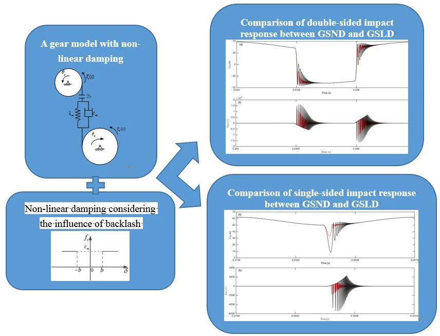
Gear rattle induced by backlash between meshing gears results in excessive vibration and noise in many gear systems. A dynamic model of a light-loaded spur gear pair with non-linear damping under no lubrication condition is presented in this paper. Unlike previous models, the effect of backlash on damping is considered, so the damping is not linear. In order to illustrate the effect of non-linear damping on the dynamic response, the dynamic behaviors of gear system with non-linear damping (GSND) and linear damping (GSLD) under different impact status are compared by using the numerical integration method. The results show that the behavior of gear pair with non-linear damping is different from that with linear damping, and the impact vibration of GSND is much greater than GSLD under some conditions. The influences of parameters such as load ratio, load value, meshing stiffness, and damping ratio on the dynamic responses of GSND are also discussed, and some suggestions to reduce impact vibration of gear system are proposed. The results provide a theoretical basis for the design and manufacture of gear system.
Highlights
- The FORTRAN computation of gear system is used.
- A gear model concluding non-linear damping influenced by backlash is modeled.
- The behavior of gear pair with non-linear damping is different from that with linear.
1. Introduction
Gear transmission system is widely used in power transmission devices, such as aviation, automotive, ships and other industrial fields. Vibration and noise of transmission has a seriously influence on performance and quality of a product, and leads customers’ complaints. The dynamic performance of gear system has become the most interesting research areas in recent decades. The influence of backlash on dynamic behavior of gear system is widely considered, for example [1-7]. The main noise in the transmission is known as gear-rattling noise and gear-clattering noise. The noise is called as gear-rattling when the transmission is in neutral, and as gear-clattering when the gear is engaged under power [8-11]. Gear rattle may occur in the teeth of the unloaded or light-loaded gear pairs because of the presence of backlash [8, 9, 12, 13]. There are many factors affecting gear rattle. The parameters responsible for rattle were classified as geometric parameters and operational parameters [10, 11, 14-18].The geometric parameters included the module, number of teeth, helix angle, axial clearance and backlash, and the operational parameters included the angular acceleration and excitation frequency [10, 11, 14-18].
Some researchers didn’t consider the effect of lubricant film because they believed that the reason of gear rattle problem was due to the solid-to-solid contact generated by the driving/driven torque variation [19-25]. Singh gave a simplified physical model of the rattle problem and demonstrated its application, in which the impact damping was ignored [19]. Wang analyzed two idealized mathematical models considering time-varying backlash, impact and displacement excitations [20]. Later, he presented the experimental results for the 3-mass system, and confirmed the computer predictions agreed with actual responses [21]. Kiyohiko introduced a developed simulator for rotational vibration and strain at root in a power transmission spur gear [22]. Cai proposed a modified stiffness function for the simple analysis of the vibration problem of a helical gear pair, but the influence of teeth separation on damping was ignored [23]. Kim developed linear and non-linear mathematical models of the driveline to understand, quantify and control the rattle problem, without considering the meshing damping [24]. Yoon constructed a linear time-invariant system model including flywheel and clutch, and applied a numerical analysis to the gear rattle motion [14]. Considering the stiffness and damping as time-invariant, Bozca presented the optimisation of gearbox geometric design parameters to reduce gear rattle noise in an automotive transmission [8].
Although the literature survey indicates that the gear rattle problem has been widely studied, some developments are still needed to ensure the accuracy of modeling. Due to the presence of backlash, the damping force only exists when the gear teeth are in contact, but it disappears when the gear pair are separated from each other. However, some literatures mentioned above did not consider the non-linear damping of gear system. For example, the literatures [19-21, 24] ignored the meshing damping, while the literatures [8, 14, 22, 23] regarded the damping as a constant. In this paper, the model of a light-loaded gear pair including non-linear damping is built to study the rattle problem. The main purpose of the present work is to investigate the influence of non-linear damping on the dynamical behavior, which can provide a reference for modeling gear rattle problem. And also, the influence of the gear system parameters considering non-linear damping on the dynamical behaviors is analyzed.
The paper is organized as follows: section 1 introduces the previous relevant studies, describes the proposed problem in this area and explains the main objective of this study. Next, the dynamic model of gear rattle incorporated the non-linear damping is constructed in Section 2. In Section 3, the dynamic behavior with non-linear damping and conventional linear damping gear system are compared by using the numerical integration method. Then, the effects of different parameters such as load ratio, load value, meshing stiffness and damping ratio on the dynamic characteristics of gear model are demonstrated in Section 4. Finally, Section 5 presents some conclusions.
2. Dynamic model of a gear system
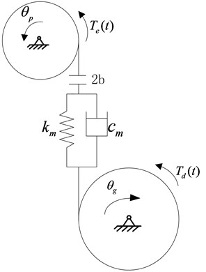
The dynamic model of a spur gear pair considering non-linear damping is constructed with rotational displacements (, ) as their coordinates shown in Fig. 1. The mass moments of inertias of the pinion and the gear are given by and , respectively. 2 is the total backlash. is the meshing stiffness of the gear pair. is the damping of the gear pair. and are the torque acted on the pinion and the gear, respectively.
Fig. 1Dynamic model of a gear pair
The corresponding equation of the gear system can be obtained by the Lagrange equation, as shown in following equation:
where and can be expressed as follows:
Eq. (1) can be simplified as:
here:
is the dynamic transmission error (DTE). is the equivalent mass of the gear pair. and are respectively the non-linear damping function and meshing displacement function. and are respectively the excitation frequency and the initial phase of fluctuation exciting force. The mean exciting force and the amplitude of fluctuation exciting force can be respectively expressed as follows:
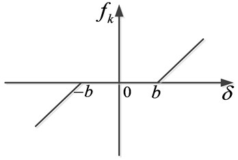
Mainly due to the presence of backlash and gear transmission error, gear teeth cannot always keep meshing, which results in repeated collision and causes vibration and noise. The damping is present when the gear pair remains in contact, while it disappears when the gear pair is separated. The model regarding the damping as linear only considered the case that the gear pair remained engaged, and did not consider the case of gear pair separation, which was inconsistent with the actual working condition of gear pair. Considering the influence of the gear pair separation on the damping, this paper adopts the non-linear damping which is consistent with the actual working condition. If the backlash is assumed symmetrical, and can be expressed as Fig. 2 and Fig. 3, respectively.
Fig. 2Non-linear damping function
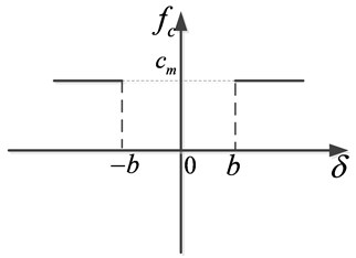
Fig. 3Meshing displacement function
Unlike conventional linear damping, the non-linear damping is described as:
here, is related to meshing stiffness and damping ratio as follow:
can be expressed as:
here, is defined as:
3. Effect of non-linear damping on dynamic response
In order to easily demonstrate the influence of the non-linear damping on the dynamical response, the comparisons with conventional linear damping [5, 8, 14] are performed. In order to guarantee computational precision, the simulation is programmed in FORTRAN using variable step Runge-Kutta numerical integration routine (ODE23s), which is more suitable for a ‘stiff’ ordinary differential equation. Since the steady state response of the system is of major interest, it is necessary to run the numerical program sufficiently long until the difference between the last two periods of DTE is less than 1×10-11 μm.
Considering the influence of load ratio (), the simulation is performed for three different load ratio: 0.5, 0.996, and 2, which are corresponding to double-sided impact, single-sided impact, and non-impact, respectively. The simulation is based on parameters listed in Table 1, and the initial conditions of the system are assumed as: 0, 0, and 0.
Table 1Parameters of the gear system
Parameter/property | Gear | Pinion |
Number of teeth | 46 | 25 |
Polar moment of inertia (Kg∙m2) | 1.63×10⁻⁴ | 1.39×10⁻⁴ |
Pressure angle (°) | 20 | |
Backlash (mm) | 0.05 | |
Module (mm) | 2 | |
Meshing stiffness (N/m) | 1×10⁸ | |
3.1. Comparison of double-sided impact status
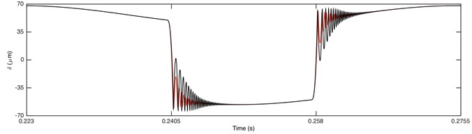
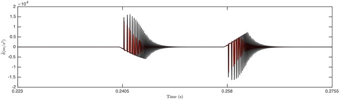
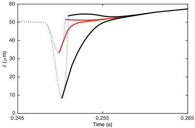
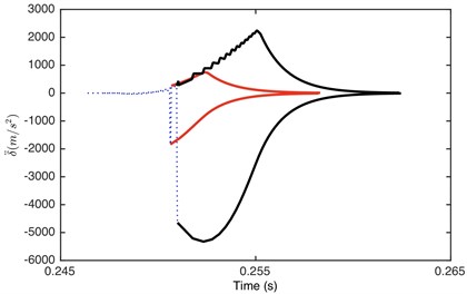
Fig. 4 shows the time history of DTE and its acceleration for double-sided impact status only in one cycle time. The results indicate that collision occurs several times on both driving and driven side before switching over to the other side, which is because the first impact is not strong enough to propel the tooth to the other side, and several impacts are required for the contact side to switch. It can be seen that the curves of non-linear damping and linear damping well coincide with each other in the non-impact region. However, the amplitude of DTE for non-linear damping in impact region is larger than that for linear damping. That is because the total damping force of non-linear damping is smaller due to the absence of damping when gear pair is separated. Consequently, the attenuation to impact vibration of GSND becomes weaker, and then the amplitude of GSND is larger than GSLD. Additionally, GSND has more number of tooth impact, longer time of tooth impact, and larger amplitude of DTE and acceleration than GSLD, which indicates that the impact vibration of GSND is much greater than GSLD.
Fig. 4Comparison of time history for: a) DTE, b) acceleration when Fm= 600 N and α= 0.5. Non-linear damping (black), linear damping (red)
a)
b)
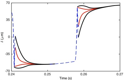
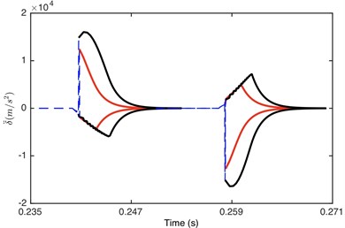
Fig. 5Comparison of envelope for: a) DTE, b) acceleration when Fm= 600 N and α= 0.5. Non-linear damping (black), linear damping (red)
a)
b)
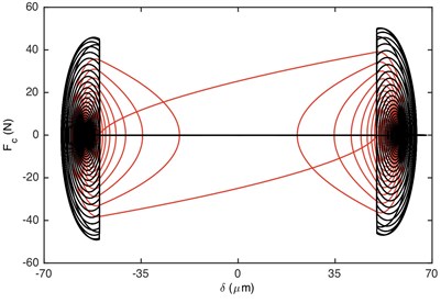
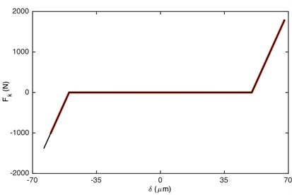
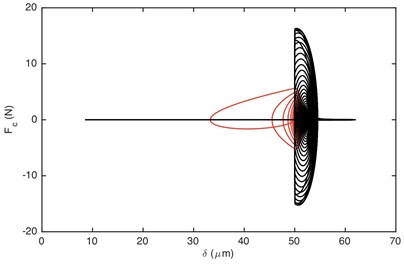
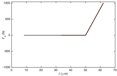
Fig. 6Comparison of: a) damping force, b) stiffness force when Fm= 600 N and α= 0.5. Non-linear damping (black), linear damping (red)
a)
b)
Fig. 6 illustrates the comparison of damping/stiffness force between GSND case and GSLD case. As shown in Fig. 6(a), the non-linear damping force is zero within the gear backlash, which also explains why the absolute maximum value of DTE for GSND attenuates more slowly than that in GSLD in the beginning of impact regions (shown in Fig. 5). Additionally, the damping force of GSND is larger than that of GSLD when 50 μm. It can be seen from Fig. 6(b) that the stiffness force of GSND is larger than that of GSLD in driven side, which suggesting a larger deformation in this side.
3.2. Comparison of single-sided impact status
With the increased load ratio, the meshing time in driving side becomes longer, while that in driven side becomes shorter. When the collisions on the driven side disappears, the dynamic response changes from double-sided impact to single-sided impact, as shown in Fig. 7.
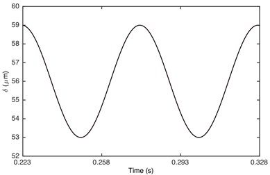
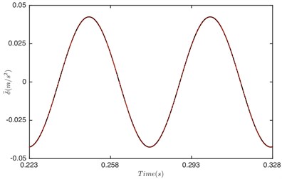
Fig. 7Comparison of time history for: a) DTE, b) acceleration when Fm= 600 N and α= 0.996. Non-linear damping (black), linear damping (red)
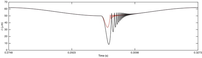
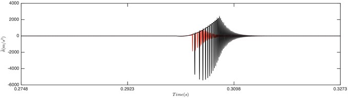
Fig. 8Comparison of envelope for: a) DTE, b) acceleration when Fm= 600 N and α= 0.996. Non-linear damping (black), linear damping (red)
a)
b)
Fig. 7 demonstrated that it is driving-sided impact. The comparison of DTE and its acceleration between GSND and GSLD has the same tendency as double-sided impact. Compared with the double-sided impact, the DTE and its acceleration of the single-sided impact is smaller. Fig. 9(a) shows that the damping force of GSLD exists in all the regions of its DTE, while that of GSND exists only when 50 μm, which is consistent with the characteristic of non-linear damping. Additionally, the damping force of GSND is larger than that of GSLD when 50 μm. Fig. 9(b) illustrates that the amplitudes of stiffness force are equal for both GSND and GSLD case.
Fig. 9Comparison of: a) damping force, b) stiffness force when Fm= 600 N and α= 0.996. Non-linear damping (black), linear damping (red)
a)
b)
3.3. Comparison of non-impact status
Single-sided impact is a transient status from double-sided impact to non-impact. When 1, the response of gear system changes to non-impact status. Fig. 10 illustrates that the response of gear system is periodic motion. It is obviously that the response of GSND is exactly the same as that of GSLD. This is because the damping function and displacement function are the same (as shown in Fig. 2 and Fig. 3) due to both of the DTE larger than 50 μm under this condition.
Fig. 10Comparison of time history for: a) DTE, b) acceleration when Fm= 600 N and α= 2. Non-linear damping (black), linear damping (red)
a)
b)
From the comparison in part 3, it is concluded that the dynamic behavior in non-impact status has no difference between the non-linear damping system and linear damping system. However, it is very different in other two meshing status. The vibration of non-linear damping system is much stronger than that of linear damping system in the double-sided impact and single-sided impact. Therefore, it is unreasonable to consider the damping as linear, and the non-linear damping model that consistent with the actual gear pair motion is more precise than linear damping.
4. Influence of parameters on dynamic response
Considering that the impact vibration in double-sided impact is more severely, the influence of parameters on double-sided impact status for non-linear damping system is discussed in this section. In order to illustrate the influence on dynamic response of non-linear damping system, the parameters such as load ratio, load value, meshing stiffness, and damping ratio are discussed respectively.
4.1. Influence of load ratio
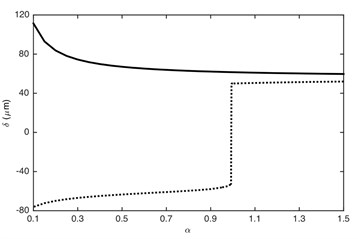
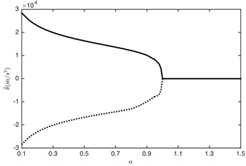
The load ratio has great influence on response characteristics of the gear system [18]. Therefore, it is necessary to pay more attention to it. In order to further illustrate the influence of load ratio, the maximum and minimum values of DTE and its acceleration in the impact region are shown in Fig. 11.
Fig. 11Influence of load ratio on: a) DTE, b) acceleration. –– Maximum value, --- minimum value
a)
b)
It can be seen that the maximum and minimum values in impact regions are largely influenced by the load ratio. The amplitude of DTE and its acceleration reduces with the increased load ratio, which is consistent with the results presented in section 3. The increase of could lead to the reduction of the amplitude of the excitation force . Consequently, the impact becomes slighter: the meshing status of the gear system changes from double-sided impact ( 0.9938) to single-sided impact () and then to non-impact ( 1). It is obvious that 1 is the critical point between impact status and non-impact status. Furthermore, due to the single-sided impact is a transient dynamic behavior, thus when load ratio is very close to 1, the minimum value of DTE changes quickly from negative to positive value (change to driving-sided impact), as shown in Fig. 11(a).
4.2. Influence of load value
Fig. 12 illustrates that the maximum and minimum value is greatly influenced by the load value. No matter what the value of load ratio, the absolute values of DTE increase with the increased load value. Additionally, the influence of load value on the maximum and minimum values of DTE is non-linear. The larger load value has a greater influence on the maximum and minimum values of DTE than the smaller one.
4.3. Influence of meshing stiffness and damping ratio
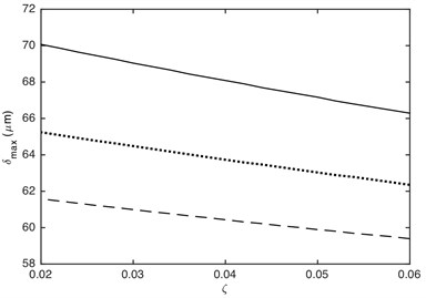
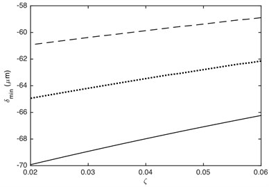
The meshing stiffness and damping ratio directly affects the value of stiffness force and damping force, which will affect dynamic response of gear system. Fig. 13 shows that the maximum and minimum values of DTE can be dramatically influenced by the meshing stiffness. The absolute value of DTE decreases with the increasing of meshing stiffness. This is because the larger the meshing stiffness, the less deformation of contact gear pair when it collides. Additionally, the effect of meshing stiffness on the maximum and minimum values of DTE is non-linear. The smaller meshing stiffness has a greater influence on the maximum and minimum values of DTE than the bigger one. Fig. 14 illustrates that the absolute value of DTE decreases as the increased damping ratio, which is because that the attenuation on impact vibration becomes more powerful with the increasing of damping ratio. It also can be seen that the effect of damping ratio on the maximum and minimum values of DTE is linear.
Fig. 12Influence of load value on DTE: a) maximum value, b) minimum value. –– α= 0.2, ··· α= 0.4, --- α= 0.7
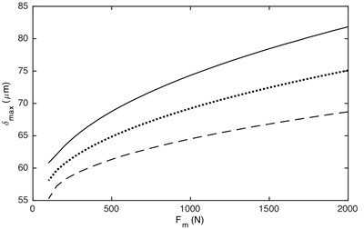
a)
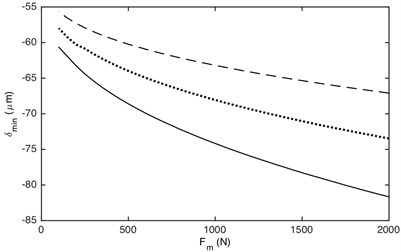
b)
Fig. 13Influence of meshing stiffness on DTE: a) maximum value, b) minimum value. –– α= 0.2, ··· α= 0.4, --- α= 0.7
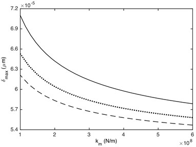
a)
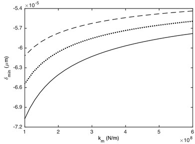
b)
Fig. 14Influence of damping ratio on DTE: a) maximum value, b) minimum value. –– α= 0.2, ··· α= 0.4, --- α= 0.7
a)
b)
5. Conclusions
1) Compared with linear damping system, the dynamic behaviors of gear system with non-linear damping has no differences in non-impact status, but they are very different in double-sided impact and single-sided impact. The gear system with non-linear damping has larger DTE and much more severe impact vibration than linear damping system in impact status, so the non-linear damping should not be ignored when analyzing the gear rattle problem. Non-linear damping model is more suitable for practical gear pair meshing, so it is more precise than linear damping
2) Load ratio can make complicated influence on dynamic characteristics of non-linear damping gear system, which not only affects the value of DTE and its acceleration, but also affects the impact status of gear system. The meshing status is double-sided impact when , single-sided impact when , and non-impact status when .
3) Some parameters have great influence on the dynamic response. For example, exciting force, backlash, damping ratio and mesh stiffness could bring about different effects to the dynamic behavior of gear pair. Large damping ratio and meshing stiffness could contribute to the reduction of DTE and impact vibration, and small exciting force are beneficial for reducing vibration. Actually, the dynamic characters are affected by various parameters simultaneously. In the actual design, the parameters should be good match to reduce the vibration.
References
-
Theodossiades S., Natsiavas S. Non-linear dynamics of gear-pair systems with periodic stiffness and backlash. Journal of Sound and Vibration, Vol. 229, Issue 2, 2000, p. 287-310.
-
Theodossiades S., Natsiavas S. Periodic and chaotic dynamics of motor-driven gear-pair systems with backlash. Chaos, Solitons and Fractals, Vol. 12, Issue 13, 2001, p. 2427-2440.
-
Walha L., Fakhfakh T., Haddar M. Backlash effect on dynamic analysis of a two-stage spur gear system. Journal of Failure Analysis and Prevention, Vol. 6, Issue 3, 2006, p. 60-68.
-
Walha L., Fakhfakh T., Haddar M. Nonlinear dynamics of a two-stage gear system with mesh stiffness fluctuation, bearing flexibility and backlash. Mechanism and Machine Theory, Vol. 44, Issue 5, 2009, p. 1058-1069.
-
Lu J.W., Chen H., Zeng F.L., Vakakis A. F., Bergman L. A. Influence of system parameters on dynamic behavior of gear pair with stochastic backlash. Meccanica, Vol. 49, Issue 2, 2014, p. 429-440.
-
Karagiannis K., Pfeiffer F. Theoretical and experimental investigations of gear-rattling. Nonlinear Dynamics, Vol. 2, Issue 5, 1991, p. 367-387.
-
Wang M. Y., Zhao W., Manoj R. Numerical modeling and analysis of automotive transmission rattle. Journal of Vibration and Control, Vol. 8, Issue 7, 2002, p. 921-943.
-
Bozca M. Transmission error model-based optimisation of the geometric design parameters of an automotive transmission gearbox to reduce gear-rattle noise. Applied Acoustics, Vol. 130, 2018, p. 247-259.
-
Bozca M., Fietkau P. Empirical model based optimization of gearbox geometric design parameters to reduce rattle noise in an automotive transmission. Mechanism and Machine Theory, Vol. 45, Issue 11, 2010, p. 1599-1612.
-
Dogan S. N., Ryborz J., Bertsche B. Rattling and clattering noise in automotive transmissions – simulation of drag torque and noise. Tribology and Interface Engineering Series, Vol. 43, Issue 3, 2003, p. 109-121.
-
Dogan S. N., Ryborz J., Bertsche B. Design of low-noise manual automotive transmissions. Proceedings of the Institution of Mechanical Engineers, Part K: Journal of Multi-body Dynamics, Vol. 220, Issue 2, 2006, p. 79-95.
-
Ottewill J. R., Neild S. A., Wilson R. E. An investigation into the effect of tooth profile errors on gear rattle. Journal of Sound and Vibration, Vol. 329, Issue 17, 2010, p. 3495-3506.
-
Brancati R., Rocca E., Savino S., Farroni F. Analysis of gear rattle by means of a wavelet-based signal processing procedure. Meccanica, Vol. 48, Issue 6, 2013, p. 1399-1413.
-
Yoon J. Y., Lee L. Nonlinear analysis of vibro-impacts for unloaded gear pairs with various excitations and system parameters. ASME Journal of Vibration and Acoustics, Vol. 136, Issue 3, 2014, p. 031010-1-13.
-
Bertsche B., Nowak W., Stockmeier M., Dogan S. N., Ryborz J. Development process of clatter and rattle noise free (CARF-) transmissions. ASME. International Design Engineering Technical Conferences and Computers and Information in Engineering Conference, Vol. 1, 2005, p. 831-839.
-
Dogan S. N., Ryborz J., Bertsche B. Low-noise automotive transmission investigations of rattling and clattering. 3rd International Symposium on Multi-body Dynamics: Monitoring and Simulation techniques, Loughborough University, Loughborough, Leicestershire, 2004.
-
Dogan S. N. Loose part vibration in vehicle transmission-gear rattle. Turkish Journal of Engineering and Environmental Science, Vol. 23, Issue 6, 2000, p. 439-454.
-
Renato B., Ernesto R., Sergio S. A gear rattle metric based on the wavelet multi-resolution analysis: experimental investigation. Mechanical Systems and Signal Processing, Vol. 50, 2015, p. 161-173.
-
Singh R., Xie H., Comparin R. J. Analysis of automotive neutral gear rattle. Journal of Sound and Vibration, Vol. 131, Issue 2, 1989, p. 177-196.
-
Wang C. C. Rotational vibration with backlash: part 1. Journal of Mechanical Design, Vol. 100, Issue 2, 1978, p. 363-373.
-
Wang C. C. Rotational vibration with backlash: part 2. Journal of Mechanical Design, Vol. 103, Issue 2, 1981, p. 387-397.
-
Umezawa K., Sato T., Ishikawa J. Simulation on rotational vibration of spur gears. Bulletin of JSME, Vol. 27, Issue 223, 1984, p. 102-109.
-
Cai Y. Simulation on the rotational vibration of helical gears in consideration of the tooth separation phenomenon (a new stiffness function of helical involute tooth pair). Journal of Mechanical Design, Vol. 117, Issue 3, 1995, p. 323-337.
-
Kim T. C., Singh R. Dynamic interactions between loaded and unloaded gear pairs under rattle conditions. Journal of Passenger Cars: Mechanical Systems, Vol. 110, Issue 2, 2001, p. 335-342.
-
Sheng R. Y., Wang Y., Zhang L. N. Study on the nonlinear dynamics of a single-stage gear vibro-impact system. Applied Mechanics and Materials, Vol. 697, 2014, p. 161-167.
Cited by
About this article

The authors would like to acknowledge the financial support from the National Natural Science Foundation of China (Grant No. 51305378), Jiangsu Provincial Science and Technology Department (Grant No. BK20161312 and BZ2018052), and the Natural Science Foundation of the Jiangsu Higher Education Institutions of China (Grant No. 17KJB460016).
