Abstract
A system-level nonlinear dynamic model for a two-stage planetary gear transmission system of a hoist is established with the consideration of time-varying meshing stiffness, backlash, damping, and bearing stiffness. Vibrational test results are also presented in accordance with simulation results computed from the dynamic model, and engagement-impacting dynamic simulations are achieved by adapting a dynamic explicit algorithm based on this model. Accordingly, variation in the contact state in relation to the engaging position is obtained together with vibration characteristics of the transmission system. This study provides a theoretical basis for the reduction of vibration and noise for the transmission system.
1. Introduction
Compared with conventional countershaft gears, planetary gear trains have many advantages such as higher transmitted power density, improved compactness of design, and the availability of multiple speed reduction ratios, and thus, they are widely used in automobile, mining, aerospace, and marine fields. However, because of the large number of components involved and the complex dynamic coupling used in the large multi-stage planetary transmission system, excessive dynamic loads and noise are generated during the operational process, which presents a health risk to workers. Therefore, to explore dynamic characteristics, noise formation mechanism and vibrational properties of multi-stage planetary gear trains, an increasing amount of attention has been paid to construct a nonlinear dynamics model of a multi-stage planetary transmission system [1-4].
Many scholars have established dynamic models using the lumped parameter method or lumped mass method to investigate dynamic characteristics of the planetary gear transmission system. For example, Kahraman developed a nonlinear torsional vibration model of a single-stage planetary gear drive train to analyze its torsional vibration characteristics [5]. Parker studied the nonlinear dynamics of planetary gears and further compared the response using the torsional lumped parameter model and finite element model, respectively [6]. He also researched the influence of teeth modification on the dynamics of planetary gears, and proposed an analytical model after the modification of the sun-planetary gear pair and ring gear-planetary gear pair [7]. Perturbation analysis has also been adopted to verify the influence of the modification on the dynamic response of planetary gears. In this respect, Bahka concluded that the amount of modification involved significantly affected gear meshing stiffness, the meshing phase, and other parameters [8]. Ambarisha studied the nonlinear dynamics of a spur teeth planetary drive train using an analytical method and the finite element method [9], and showed that when the meshing frequency and its harmonics are close to the inherent frequency of the planetary gear train, the spectrum of the planetary gear train shows a nonlinear jump, chaotic motion, period-doubling bifurcations, and other nonlinear phenomena. In addition, Parker designed experiments to study the influence of torque on the dynamic behavior and system parameters of a planetary gear train [10], and his results showed that with a change of torque, mode shapes and damping ratio also changed. Abousleiman proposed a lumped parameter model and finite element mixed models that were capable of acquiring the dynamic behavior of a planetary drive[11]. Kiracofe investigated the structured vibration mode and natural frequency of different compound planetary gears [12], showing that vibration modes could be classified into rotational, translational, planet modes, and additionally examined unique properties of different planetary types. Inalpolat developed a generalized dynamic model for multi-stage planetary gear trains used in automotive automatic transmissions [13]; natural modes were computed on the basis of this model by solving the corresponding eigenvalue problem, and the forced vibration response to gear meshing excitations was obtained by applying the modal summation technique. Furthermore, Guo studied the sensitivity of general compound planetary gear natural frequencies and vibration modes to inertia and stiffness parameters [14].
Although these previous studies researched dynamic characteristics of a planetary gear set by considering of many factors, most research has been focused on single-stage planetary gear set. In addition, a system-level dynamic model, which was constructed using either the lumped parameter method or lumped mass method, cannot completely describe the dynamic influences resulting from various nonlinear dynamic excitations such as the gear meshing impact and other nonlinear contact.
With the aim of solving these problems, a nonlinear dynamic model is proposed for a two-stage planetary gear transmission system of a hoist by considering time-varying meshing stiffness, backlash, damping, and bearing stiffness. In addition, a transient dynamic analysis of a multi-stage planetary gear transmission system is implemented, and the system’s the vibration characteristics are researched.
2. Gear contact mechanism
The key issue involved in representation is to consider how to correctly illustrate the contact involved in a gear transmission system because this influences the efficiency and accuracy of dynamics computation. In this study, several contact parameters, such as the static friction factor, dynamic friction and the viscous damping factor, are defined to calculate the dynamic problem of gear contact. In addition, a penalty function is also used for gear meshing and for the contact of bearing encloses [15]. Fig. 1 illustrates the teeth contact of two gears during the process of meshing at time . is the interface of the two contact teeth at that moment. and are respectively the contact surface of teeth and . Generally, is called the driven surface and is the driving surface.
Fig. 1Contact schematic of two gears
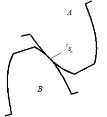
Fig. 2Local coordinates of contact surface
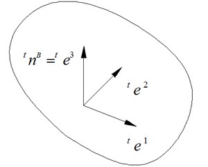
To analyze the dynamic properties during the meshing process, a local coordinate is established on the driving surface , as shown in Fig. 2. Three vector of the local coordinate are , and , respectively. Herein, and are located in the tangent plane of , and is the unit normal vector of . The relationship of , and can be expressed as:
To clarify this description, the contact teeth were separated at a distance, as shown in Fig. 3. Here, the contact force between and can be written as:
where and are the normal and tangential components of , respectively. In addition, and can be expressed as:
According to Newton’s third law of motion, the equation that can be obtained is as follows:
Fig. 3Contact surface and contact force
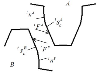
Fig. 4Pair of contact points and associated distance
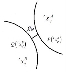
Contact faces of two gears should not be infiltrated with each other during engagement process. If is the coordinate of a point on at moment , and then the distance between and the contact surface can be written as, as shown in Fig. 4:
Assuming that is a smooth surface, the component along the direction of of can then be expressed as:
where, , the subscript of , represents the distance measured along the normal direction .
To satisfy the non-infiltration requirement, for any given point on the surface , can be defined as:
Eq. (8) can also be written as:
and the noninfiltration requirement at the moment of can be defined as:
where:
where and are the displacement increments from to . That is:
After integrating, the non-infiltration requirement can be written as:
where and are the displacement increments along the direction of for driven contact point and driving contact point, respectively. is the distance between the driven and driving contact points along the direction of . , and are defined as:
The total potential energy functional of a contact gear pair during the transmission process can be expressed as:
where is the potential energy functional that does not include the constraint condition, and is the additional functional with the consideration of the constraint condition by applying the penalty function. For the state of viscoelastic contact, the additional functional and its variational form can be expressed as:
where , and are the penalty parameters corresponding to the directions of , and , respectively.
According to , the solution equation for the gear contact problem can be obtained. Meanwhile, , the virtual work of contact force on the contact face, can be written as:
The contact force on the contact face can be defined as:
For the state of sliding frictional contact, the contact force can be written as:
where is the friction coefficient. The virtual work can be repressed as:
The coefficient matrix is in accordance with the resolving equations which are used to solve the contact problem, including that of inertia component via an explicit numerical integration method.
3. Dynamic modeling of multi-stage planetary gear transmission system
This study focuses on a hoist equipped with a two-stage planetary gear reducer. Table 1 shows some of the parameters of the planetary gear transmission system involved. For simplicity in dividing the finite element grid, round orifices and chamfer angles are ignored. With the comprehensive consideration of computational size and precision, an explicit hexahedral element and explicit shell element are adopted. Fig. 5 shows the nonlinear contact dynamic model of planetary gear driveline.
Table 1Parameters of gear transmission system
First-stage planetary gear set | Second-stage planetary gear set | |
Number of sun gear teeth | 25 | 21 |
Number of planet teeth | 34 | 25 |
Number of inner ring gear teeth | 95 | 71 |
Number of planet teeth | 3 | 4 |
Modulus | 10 | 16 |
Tooth width | 200 | 250 |
Gear ratio | 4.8 | 4.381 |
Fig. 5A system-level nonlinear dynamic model of a hoist Equipped with a two-stage planetary gear transmission system
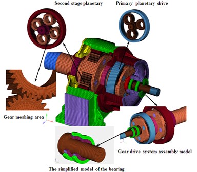
It is not possible to directly load speed and torque on the finite element node of input shaft and output shaft, two sections of auxiliary shell grids are built to connect the input and output shaft. Speed and torques are loaded on the shell elements. Table 2 lists the basic gear design parameters of planetary gear system.
Table 2Mechanical properties of planetary gear transmission system
Component | Material | Elastic modulus (MPa) | Density (kg/m3) | Poisson’s ratio | Yield limit (MPa) |
Input shaft | 42CrMo | 2.12E5 | 7850 | 0.28 | 1150 |
Front of box and base | HT200 | 1.4 E5 | 7800 | 0.25 | 310 |
First stage carrier | ZG35CrMo6 | 2.2 E5 | 7870 | 0.3 | 580 |
First and second stage sun gear | 17CrNiMo6 | 2.06 E5 | 7870 | 0.26 | 1260 |
First and Second stage planet | 17CrNiMo6 | 2.06 E5 | 7870 | 0.26 | 1260 |
First and Second stage ring gear | 30Cr2Ni2Mo | 1.75 E5 | 7850 | 0.3 | 590 |
First and Second stage of planet axle | 40Cr | 2.06 E5 | 7900 | 0.28 | 785 |
Second stage carrier | 35CrMo | 2.06 E5 | 7800 | 0.3 | 835 |
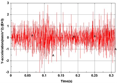
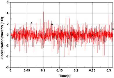
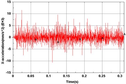
Fig. 6Computed results of measurement points
a) Point 1 ()
b) Point 2 ()
c) Point 3 ()
d) Point 4 ()
e) Point 5 ()
f) Point 6 ()
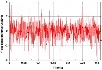
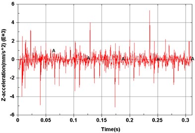
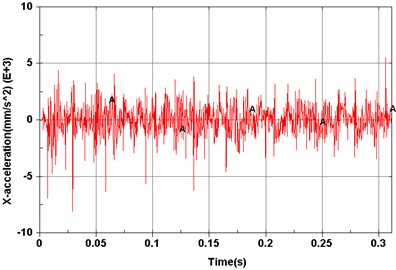
Dynamic simulations were then performed to explore vibration characteristics of the planetary gear transmission system by implementing the constructed dynamic model. The revolving speed of the input shaft was 500 r/min, and the resistance torque was 0 N·m. Model elements corresponding to experimental measuring points are shown in Fig. 5. Acceleration signals of different measuring points on the dynamic model are shown from Figs. 6(a)-(f).
To research the way in which vibration characteristics of the planetary gear transmission system varying with gear meshing position, a dynamic transient analysis of the planetary gear driveline is carried out. Fig. 7(a) and Fig. 7(b) show the vibrational displacement of transmission system at moments of 0.135 s and 0.33 s, respectively. As shown in Fig. 7, the largest vibration parts of gearbox housing are situated at the front and back bearing pedestal of the cover, as well as in the area of contact between the box base and ring gear. The largest vibration area of the transmission box varies with the operating of the planetary gears, and this is in accordance with the generating mechanism and the transfer path of the vibration of transmission system vibration.
Fig. 7Vibrational displacement of gearbox housing
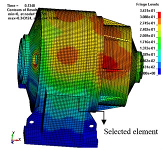
a) Box vibrational displacement at 0.135 s
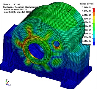
b) Box vibrational displacement at 0.33 s
4. Test and model validation
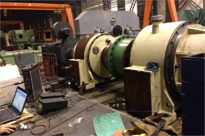
To verify the accuracy of the analysis theory, dynamic model and simulation results, as well as to explore vibration characteristics, noise and vibration tests of the planetary gear transmission system were conducted. The test rig and environment used are shown in Fig. 8. The input of the transmission system is driven by a servomotor, and the output is connected to a speed increaser with a gear ratio is equal to the reducer of the hoist. Consequently, different working conditions are achieved by changing the output power of the servomotor.
Fig. 8Test rig
Six measuring points, corresponding to the test points of the dynamic model, were arranged on the transmission system, as shown in Fig. 9. Measuring point 1 is located on the left cover close to the first stage ring gear; measuring points 2 and 3 are positioned on the top and left of the input bearing pedestal cover, respectively; point 4 is located on the left stiffener of frame; point 5 is arranged on the top of frame near the second ring gear, and test point 6 is located on the top of the output bearing pedestal cover. The revolution speed of the input shaft was 500 rpm, and the loading torque of output was 0 Nm. Figs. 10(a)-(f) show the acceleration signals recorded at the test points.
Fig. 9Locations of measuring points
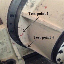
a) Test point 1and 4
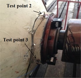
b) Test point 2 and 3
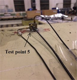
c) Test point 5
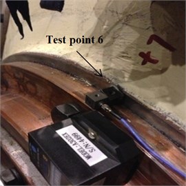
d) Test point 6
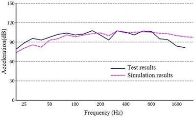
The acceleration signals of the tests and simulations are represented by 1/3 octave, and the 1/3 octave structure noise can be defined as:
where is the acceleration structure noise of the 1/3 octave (dB), is the acceleration effective value of a frequency band with the center frequency of a certain frequency (m/s2), and is the standard acceleration and 1×10⁻⁶ m/s2.
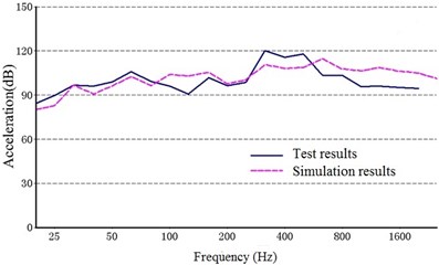
Fig. 11 shows a comparison between the acceleration structural noise of a 1/3 octave in the test results and the simulation. The solid line represents the experimental data, and the dashed line represents the simulation results.
As shown in Fig. 10, the structure noise generated from the experiment agreed with that from the simulation results, indicating that the dynamic model constructed in this study can be used to accurately describe the vibration characteristics of the multi-stage planetary gear transmission system.
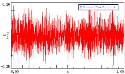
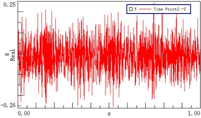
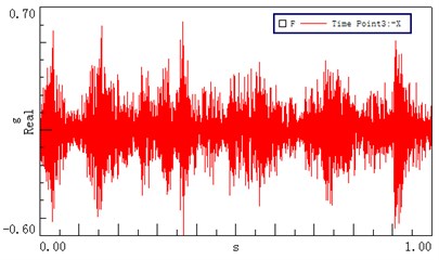
Fig. 10Time domain vibrational results recorded at different test points
a) Test point 1 ()
b) Test point 2 ()
c) Test point 3 ()
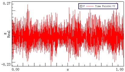
d) Test point 4 ()
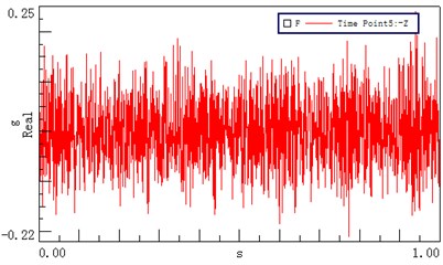
e) Test point 5 ()
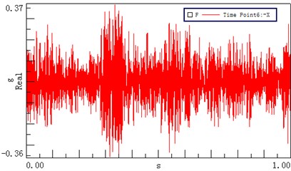
f) Test point 6 ()
5. Conclusions
A study was conducted to investigate vibration properties of a hoist equipped with a two-stage planetary gear transmission system. A system-level nonlinear dynamic model was proposed with the consideration of time-varying meshing stiffness, backlash, damping, and bearing stiffness to predict the dynamics of this two-stage planetary gear transmission system. In addition, noise and vibration tests were conducted to verify the accuracy of the analytical theory, dynamic model, and simulation results. Comparisons were performed between the results of the experimental data and the simulation, and a good agreement was found, indicating that the dynamic model established in this study can be used to describe vibration characteristics of the multi-stage planetary gear transmission system. Furthermore, the transient dynamic simulation showed that the largest vibration area of the transmission box varies with the operation of planetary gears, and this is in agreement with the generating mechanism and the transfer path of the transmission system. It is considered that further work is required to extend the structural and transient analysis to decrease the noise and vibration of the hoist based on the developed model.
Fig. 11Comparison of the structure noise between the test and simulation
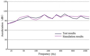
a) Point 1 ()
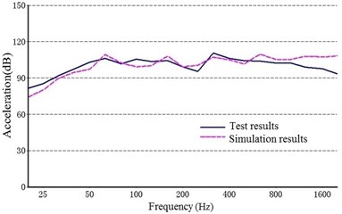
b) Point 2 ()
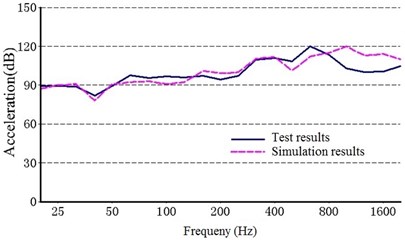
c) Point 3 ()
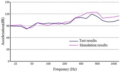
d) Point 4 ()
e) Point 5 ()
f) Point 6 ()
References
-
Kahraman A. Effect of axial vibrations on the dynamics of a helical gear pair. Journal of Vibration and Acoustic, Vol. 115, Issue 1, 1993, p. 33-39.
-
Velex P., Maatar M. A mathematical model for analyzing the influence of shape deviations and mounting errors of gear dynamic behavior. Journal of Sound and Vibration, Vol. 191, Issue 5, 1996, p. 629-660.
-
Zhang J. W., Tang X. L., Yu H. S. Multi-body dynamics and noise analysis for the torsional vibration of a power-split hybrid driveline. Proceedings of the Institution of Mechanical Engineers, Part K: Journal of Multi-body Dynamics, Vol. 228, Issue 4, 2014, p. 366-379.
-
Ozguven H. N., Houser D. R. Dynamic analysis of high speed gears by using loaded static transmission error. Journal of Sound and Vibration, Vol. 125, Issue 1, 1988, p. 71-83.
-
Kahraman A. Natural modes of planetary gear trains. Journal of Sound and Vibration, Vol. 73, Issue 1, 1994, p. 125-130.
-
Parker R. G., Agashe V., Vijayakar S. M. Dynamic response of a planetary gear system using a finite element/contact mechanics model. Journal of Sound and Vibration, Vol. 122, Issue 3, 2000, p. 305-311.
-
Parker R. G. A physical explanation for the effectiveness of planet phasing to suppress planetary gear vibration. Journal of Sound and Vibration, Vol. 236, Issue 4, 2000, p. 561-573.
-
Bahka C. J., Parker R. G. Analytical investigation of tooth profile modification effects on planetary gear dynamics. Mechanism and Machine Theory, Vol. 70, 2013, p. 298-319.
-
Ambarisha V. K., Parker R. G. Nonlinear dynamics of planetary gears using analytical and finite element models. Journal of Sound and Vibration, Vol. 302, 2007, p. 577-595.
-
Ericson T. M., Parker R. G. Experimental measurement of the effects of torque on the dynamic behavior and system parameters of planetary gears. Mechanism and Machine Theory, Vol. 74, 2014, p. 370-389.
-
Abousleiman V., Velex P. A hybrid 3D finite element/lumped parameter model for quasi-static and dynamic analyses of planetary/epicyclical gear sets. Mechanism and Machine Theory, Vol. 41, 2006, p. 725-748.
-
Kiracofe D. R., Parker R. G. Structured vibration modes of general compound planetary gear systems. Journal of Vibration and Acoustics, Vol. 129, 2007, p. 1-16.
-
Inalpolat M., Kaharaman A. Dynamic modeling of planetary gears of automatic transmissions. Proceedings of the Institution of Mechanical Engineers, Part K: Journal of Multi-body Dynamics, Vol. 222, 2008, p. 229-242.
-
Guo Y., Parker R. G. Sensitivity of general compound planetary gear natural frequencies and vibration modes. Journal of Vibration and Acoustics, Vol. 132, 2010, p. 1-13.
-
Wang X. C. Finite Element Method. Tsinghua University Press, Beijing, 2003.
About this article

This work was supported by the National Science and Technology Support Program under the Grant Number 2013BAF01B05.
