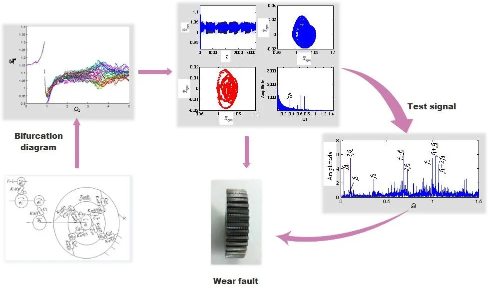
Abstract
With the increasing service life of a gear transmission system, the gear teeth become constantly worn, and the gear clearance increases. The increase in the clearance will produce a series of nonlinear changes that change the stability of the system and can even result in loss of stability. In this paper, dimensionless dynamic equations of a multistage gear transmission system that contains a two-stage fixed-axis gear and a one-stage planetary gear were established. Planetary wear fault was simulated by changes in the gear clearance. System bifurcation diagrams with an increase in the clearance were studied. The frequency characteristics of planetary gears under different excitation frequencies and different degrees of wear were studied. The influence of planetary gear wear on the fixed-axis was discovered. The vibration mechanism and a fault diagnostic method in a multistage gear transmission system were obtained.
Highlights
- By studying the time-domain, frequency-domain, phase diagram and Poincaré section of each motion state, the transition processes and frequency characteristics of each motion state were analyzed.
- Frequency characteristics of the planetary gears under different excitation frequencies and different degrees of wear were obtained.
- The influence of the planetary gear wear on the fixed-axis gear were obtained.
1. Introduction
With the increasing service life of a gear transmission system, the gear teeth become continuously worn, and the gear clearance increases. Clearance is the main reason for the collision motion inside the system. It will make the motion state of the system change or even create instability. Therefore, it is very important to study the wear mechanism and the change in the system nonlinear state, as these attributes are of great significance for the design, monitoring and diagnosis of the system. When both planetary gear and fixed-axis gear exist in the system, the vibration signal of planetary gear is weaker than that of fixed-axis gear, so the wear fault of planetary gear in multistage gear transmission system is more difficult to identify.
For the study of wear failure mechanism, based on the different classification of wear, a large number of studies have established wear calculation models based on adhesion theory [1-3], fatigue theory [4, 5], energy wear theory [6] and material wear rate [7]. It has been studied from various angles such as tooth profile [3], gap [8], dynamic response [9], and experiment [10]. However, there are many factors affecting gear wear, and the wear mechanism is closely related to the actual working condition, so it is difficult to establish a wear prediction model completely consistent with the actual transmission system. At the same time, under the condition of multi-factor coupling, wear failure has strong nonlinear characteristics. Therefore, it is particularly important to study the nonlinear characteristics of wear. Shen [11] focused on the nonlinear dynamics of a spur gear pair with slight wear fault, where the backlash, time-varying stiffness and wear fault were all included. Ding [9] and Liu [12] introduced the dynamic wear coefficient proposed by Priest [13] into the calculation of spur gear wear. Based on the multi-factor excitation nonlinear dynamic model, the coupling effect between tooth wear and system dynamic response was studied. These literature all aim at the single pair gear model, and neglect the coupling characteristics between multistage gears. However, in the multi-gear transmission system, the fault of planetary gear is more difficult to be identified due to its weak signal. Therefore, it is necessary to further study the nonlinear dynamic characteristics of the multistage gear transmission system with planetary gear wear fault.
For the fault diagnosis of wear failure, the most common test methods are ferro spectral analysis [14, 15] and time-frequency characteristic analysis of vibration signal [16, 17]. In order to facilitate the comparison of theoretical and experimental results, the time-frequency characteristic analysis method will be used in this paper. Through the mechanism analysis of gear wear, the transmission characteristics of gear wear are identified. At present, some scholars have started relevant researches. He [18] proposed a novel nonlinear time-frequency feature based on a time-frequency manifold (TFM) technique. The effectiveness and the merits of the proposed TFM feature were confirmed by case study on gear wear diagnosis, bearing defect identification and defect severity. Liu [12] proposed a dynamic wear prediction methodology to investigate the coupling effects between surface wear and dynamics of spur gear systems. This paper will also use the nonlinear time-frequency characteristics of wear fault to present a diagnostic method of wear fault.
In this paper, a nonlinear dynamic model of multistage gear transmission system that contains a two-stage fixed-axis gear and an one-stage planetary gear was established. The simulation method was used to analyze the bifurcation characteristics of the system under different clearances to find out the excitation frequency range of wear and the change in the system motion state. In order to understand the frequency characteristics of the system. The transition process and frequency characteristics of each motion state under different excitation frequencies were discussed. The vibration mechanism and a diagnostic method of wear were obtained.
2. Torsional dynamic model of a multistage gear transmission system
The system studied in this paper is a test rig with a multistage gear transmission system that contains a two-stage, fixed-axis gear and a one-stage planetary gear, where spur gears 1 and 2 compose the 1st - stage fixed-axis gear for the input, spur gears 3 and 4 compose the 2nd - stage fixed-axis gear, and the planet carrier is for the output. The torsional dynamic model is established using the lumped mass method (Fig. 1). The model does not consider the transverse vibration displacement of the gears. The gear parameters are simulated with a spring and a damper.
Fig. 1Torsional dynamic model of the multistage gear transmission system
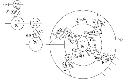
In Fig. 1, , , , , , , and represent the angular displacements of the sun gear, planet carrier, planetary gear ( 1, 2, 3, 4), and spur gears 1, 2, 3, and 4, respectively. Throughout this paper, the subscripts , , , , and 1, 2, 3, and 4 denote the sun gear, planet carrier, planetary gear, ring gear, and spur gears 1, 2, 3, and 4, respectively. The quantities , , , , , , and are the base circle radius values of the gears. The quantities , , , and denote the meshing stiffness of the sun gear with planetary gear , the ring gear with planetary gear , the 1st-stage fixed gear, and the 2nd-stage fixed gear, respectively. The quantities , , , and denote the damping of the sun gear with planetary gear , the ring gear with planetary gear , the 1st-stage fixed gear, and the 2nd-stage fixed gear, respectively. is the input, and is the output.
2.1. Motion differential equations of the system
By using the Lagrangian equation, the clearance, time-varying meshing stiffness, and composite error are considered to establish the motion differential equations of the system. After that, the motion differential equation is processed in a dimensionless way. This process has been deduced and detailed in my paper [19]. Only the final system dimensionless motion differential equations are listed here:
2.2. Wear fault
The gear tooth surface will wear out with an increase in the running time. The clearance between the teeth will change when wear occurs. When gear teeth are evenly worn, the tooth clearance will be larger than normal. To model wear failure, Flodin [20] simulated mild wear spur gears. Park [21] presented an approximate method to predict the surface wear of hypoid gears using surface interpolation. In this paper, the clearance was controlled by changing the size of the dimensionless composite error amplitude [22]. The bifurcation diagram of the multistage gear transmission system with the change in excitation frequency was calculated in the normal state. According to the clearance calculation formula given by the Chinese national standard GB 2363-90, the dimensionless clearance interval of the meshing gear in the normal state is [0.1, 1].
3. Nonlinear dynamic behavior analysis of the system with increased planetary gear wear
3.1. System bifurcation diagrams with increased planetary gear wear
By increasing the wear degree of the planetary gear 1, the influence of planetary gear wear on the excitation frequency range of the multistage gear transmission system was investigated. The minimum clearance of the multistage gear transmission system was chosen as the initial state, that is, 0.1. At this point, the system is in a periodic motion state, and it is easy to observe the changes caused by the planetary gear wear. The variable-step Runge-Kutta method was used to solve the nonlinear differential Eq. (1). The bifurcation diagrams were investigated on the meshing points of the 1st - stage fixed-axis gear, and the planetary gear with the ring gear, when the fixed-axis gear clearance was constant ( 0.1) and the planetary clearance increased gradually ( 0.1-1), as shown in Fig. 2. The gear parameters of the multistage gear transmission system are shown in Table 1 and 2. The pressure angle 20°, 6.5 N·m, 8.5 N·m, 5 μm, and the damping ratio of meshing pairs 0.07. These parameters were derived from the multistage gear transmission system test rig. We set the sampling interval as 0.01:0.01:5. Each calculates 80 rotating periods. The number of samples for each rotating period was 256 points. The bifurcation diagram started at the 25th period. The color in Fig. 2 represents 55 rotating periods. The initial velocity and displacement were set to 0. The calculation time of bifurcation diagram was 2820 s. The CPU computing time was obtained using a PC with Windows 7 operating system (Intel (E3) 3.2 GHz CPU) and 16 GB memory, and the computations were performed using MATLAB 2014a.
Table 1Gear parameters
Gear | Number of teeth | / mm | Mass / g | Rotational inertia / (g∙m2) | Face width / mm | Modulus m/mm |
1 | 29 | 20.4 | 125 | 0.05 | 30 | 1.5 |
2 | 100 | 70.5 | 1224.5 | 6 | 30 | 1.5 |
3 | 36 | 25.3 | 224 | 0.14 | 30 | 1.5 |
4 | 90 | 63.4 | 1111 | 4 | 20 | 1.5 |
s | 28 | 13 | 41 | 0.007 | 20 | 1.0 |
36 | 17 | 34.6 | 0.01 | 20 | 1.0 | |
– | 30 | 848.7 | 0.76 | 20 | 1.0 | |
100 | 47 | – | – | 20 | 1.0 |
Table 2Calculation parameters
Parameters of calculation | Value |
Gear clearance (μm) | 5 |
comprehensive meshing error amplitude (μm) | 2 |
Meshing pair damping ratio | 0.07 |
Gear contact ratio | 1.68 |
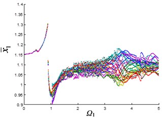
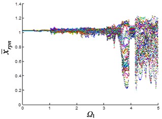
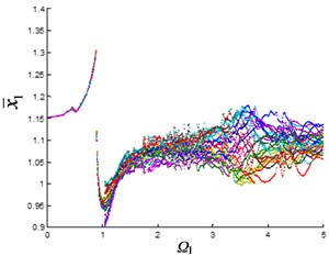
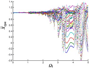
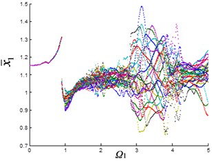
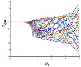
As can be seen from Fig. 2(b), the planetary gear is in single-period motion state when the excitation frequency is small. When 1, the system changes from single-period motion to multi-period motion. Until 3.5, it changes from multi-period motion to quasi-periodic motion with large oscillations. The 1st stage fixed-axis gear is also in single-period motion when the excitation frequency is small (Fig. 2(a)). Affected by the synchronism of the planetary gears, the motion of the 1st stage fixed-axis gear changes from single-period to multi-period, when 1, and when 3.5, it is also in quasi-periodic motion with large oscillations. As the wear increases (Fig. 2(d)), the excitation frequency of the quasi-periodic motion of the planetary gear advances to 2.5, and the amplitude of the quasi-periodic motion increases. Fixed-axis gear has not been affected due to the small increase in clearance (Fig. 2(c)).
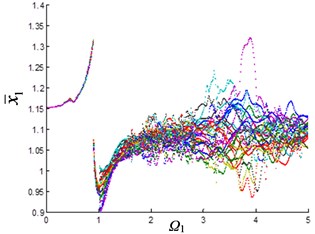
Fig. 2Bifurcation diagram of the system with the change of excitation frequency under different gaps: a) and b) e-aspn=e-arpn= 0.1, c) and d) e-aspn=e-arpn= 0.2, e) and f) e-aspn=e-arpn= 0.4, g) and h) e-aspn=e-arpn= 0.8
a)
b)
c)
d)
e)
f)
g)
h)
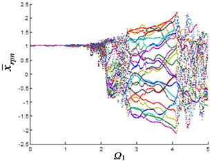
As the wear continues to increase (Fig. 2(f)), the excitation frequency of planetary gear advances to 2.1 when entering quasi-periodic motion, and quasi-periodic motion amplitude also increases. At this time, the planetary gear vibration is transmitted to the fixed-axis, so that the amplitude of the 1st stage fixed-axis gear is increased in the interval of ∈ [3, 4] (Fig. 2(e)). As the wear continues to increase (Fig. 2(h)), the excitation frequency of planetary gear advances to 1.7 when entering the quasi-periodic motion, and the amplitude of quasi-periodic motion increases significantly with 4. The influence of synchronization of the planetary gear on the fixed-axis gear is more serious. The amplitude of the interval of ∈ [3, 4] increases continuously (Fig. 2(g)).
It can be seen from Fig. 2 that the planetary gear wear mainly affects the interval of 2. In another article [23] of the author, it is found that when 2, it is mainly affected by the fixed-axis wear. The wear of the planetary gear causes the excitation frequency of the quasi-periodic motion of the planetary gear advances and increases the amplitude of the vibration. At this time, due to the synchronization, the changes of the planetary gear are transmitted to the fixed-axis gear, so that the amplitude of the quasi-periodic motion of the 1st stage fixed-axis gear is obviously increased in the interval of ∈ [3, 4].
3.2. Frequency characteristics of the planetary gears under different excitation frequencies
In order to understand the frequency characteristics of the system under different excitation frequencies and different degrees of wear, more detailed analysis of time domain, frequency domain, phase diagram and Poincaré section of each motion state are required. The large clearance state was (Fig. 2(f)) selected as the study object. At this time, the characteristics of the planetary gear and the fixed-axis gear are obvious. The dimensionless characteristic frequencies of the gears in the multistage gear transmission system are shown in Table 3. When 0.4, the dynamic characteristics of the planetary gear at different excitation frequencies were calculated, and Figs. 3-8 were obtained.
Table 3Dimensionless characteristic frequencies of multistage gear transmission system (Hz)
Characteristic frequency | Dimensional frequency |
Meshing frequency of 1st-stage fixed-axis gear | 1 |
Meshing frequency of 2nd-stage fixed-axis gear | 0.3599 |
Meshing frequency of planetary gear | 0.0877 |
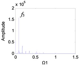
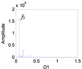
Fig. 3Dynamic characteristics of the planetary gear Ω1= 1
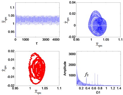
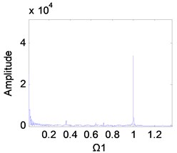
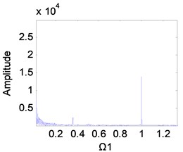
Fig. 4Dynamic characteristics of the planetary gear Ω1= 1.7
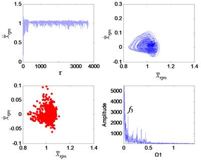
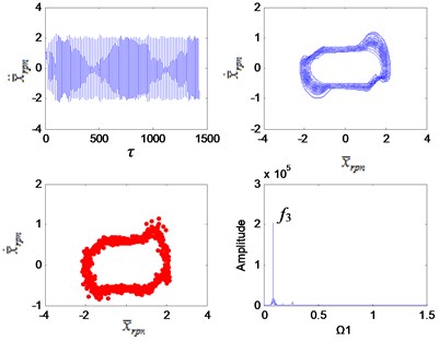
It can be seen from Fig. 3 that the system is in a single-period motion when the excitation frequency is small, and the Poincaré section is a point group. Due to the sun gear is connected to the 2nd stage fixed-axis gear, the planetary gear vibration signal is weak compared with the 2nd stage fixed-axis gear. The main peaks of the vibration spectrum are and . As the excitation frequency increases, the system leaves the single-period motion and enters a quasi-periodic motion (Fig. 5) through chaotic when the interval of ∈ [1.7, 2.1] (Fig. 4). Planetary gear vibration is intensified, and the amplitude of planetary gear meshing frequency becomes the main peak. After the quasi-periodic motion is stable, the amplitude of the planetary gear meshing frequency far exceeds that of the 2nd stage fixed-axis meshing frequency, and the main peaks at this time are and its higher harmonics. Subsequently, the system undergoes loop surface doubling (Fig. 6), and obvious nonlinear characteristics appear in the spectrum, which is represented by the high amplitude of the sub-harmonic /2. After the system is stable, it maintains the quasi-periodic motion again (Fig. 7). The main peaks of the spectrum are still and its higher harmonics, but the amplitude of increases with the increase of excitation frequency (Fig. 8).
Fig. 5Dynamic characteristics of the planetary gear Ω1= 2.4
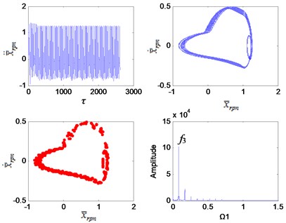
Fig. 6Dynamic characteristics of the planetary gear Ω1= 2.5
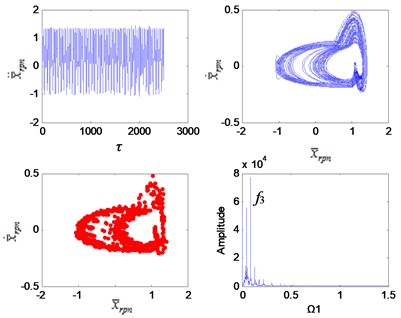
Fig. 7Dynamic characteristics of the planetary gear Ω1= 2.9
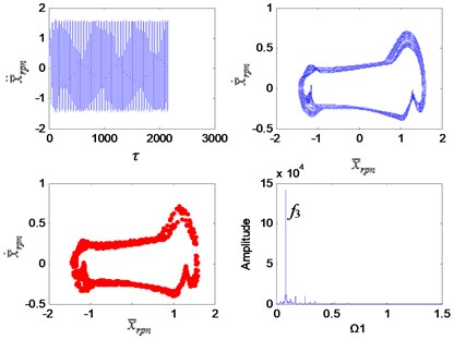
Fig. 8Dynamic characteristics of the planetary gear Ω1= 4.4
When 1.7, the vibration characteristics of the planetary gears are more prominent than the fixed-axis gear. The increase of the planetary gear clearance has little effect on low frequencies, but has a great influence on high frequencies, which greatly increases the amplitude of . The planetary vibrations are only sensitive to high excitation frequencies, and their characteristics are not visible at low excitation frequencies. However, such high excitation frequencies are often not achieved in engineering applications. Therefore, planetary gear wear is relatively the least identifiable fault in the system.
3.3. Frequency characteristics of the planetary gears under different degrees of wear
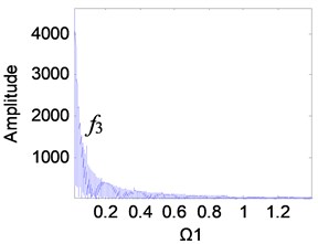
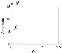
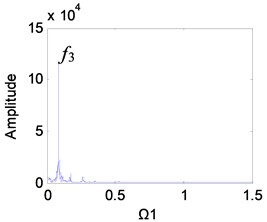
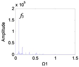
The interval where the vibration characteristics of the planetary gear are obvious is selected as the research object, that is, when 3. The frequency characteristics of the planetary gear changed with the degree of planetary wear were investigated, as shown in Fig. 9.
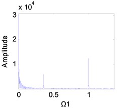
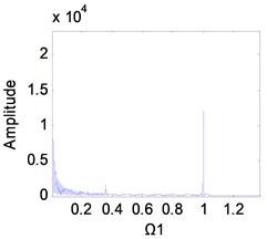
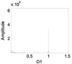
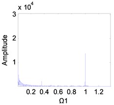
It can be seen from Fig. 9 that as the clearance increases, the planetary gear keeps periodic motion, and the main peaks of the frequency are always and its higher harmonics, but the amplitude of the frequency increases significantly. When the clearance is small, the planetary gear is in single-period motion, and the vibration amplitude of the meshing frequency is also small (Fig. 9(a)). The clearance gradually increases. When 0.2-0.6, the amplitude increases rapidly (Figs. 9(b)-(d)). At this time, the wear enters the development period, and the slight increase of wear will be reflected in the spectrum. When the wear is 0.6-1, the amplitude growth becomes slower (Figs. 9(e) and (f)).
Fig. 9Frequency characteristics of the planetary gears: a) e-aspn=e-arpn= 0.1, b) e-aspn=e-arpn= 0.2, c) e-aspn=e-arpn= 0.4, d) e-aspn=e-arpn= 0.6, e) e-aspn=e-arpn= 0.8, f) e-aspn=e-arpn= 1
a)
b)
c)
d)
e)
f)
3.4. The influence of the planetary gear wear on the fixed-axis gear
The above research results only appear in the experimental simulation. In practical engineering applications, the planetary gear signals are often coupled with the fixed-axis gear signals to become complex mixed signals, which making the planetary gear signals difficult to identify. The 1st stage fixed-axis signal is closer to the input end, so the signal interference is small, and the vibration frequency is high. In the extracted experimental signals, the information components are many and clear. Therefore, frequency characteristics on the meshing point of the 1st stage fixed-axis gear are studied to investigate whether the planetary gear wear signals can affect the fixed-axis ones. The frequency characteristics on the 1st stage fixed-axis meshing point were investigated under different degrees of wear and different excitation frequencies. The results are shown in Figs. 10, 11.
Fig. 10Frequency spectrum diagram of the 1st stage fixed-axis gear, when e-aspn=e-arpn= 0.2: a) Ω1=1, b) Ω1= 2, c) Ω1= 3, d) Ω1= 4
a)
b)
c)
d)
Fig. 11Frequency spectrum diagram of the 1st stage fixed-axis gear, when e-aspn=e-arpn= 0.4: a) Ω1= 1, b) Ω1= 2, c) Ω1= 3, d) Ω1= 4
a)
b)
c)
d)
It can be seen from Fig. 2(g) that the excitation frequency range of the 1st stage fixed-axis gear affected by the wear of the planetary gear is mainly [3, 4]. Comparing Figs. 10(a), (b) and 11(a), (b), it can be seen that when 1 and 2, the spectrum has no change. In Figs. 10(c) and (d), the amplitude of the planetary gear meshing frequency is masked due to the slight wear. But with the wear increase, appears in Figs. 11(c) and d. In Fig. 11(d), the amplitude of has exceeded , indicating that the planetary gear wear characteristics can be reflected in the fixed-axis spectrum. But the planetary gear characteristics are only obvious when the wear progresses to the medium term and the excitation frequency is sufficiently large.
4. Test signals identification and diagnosis
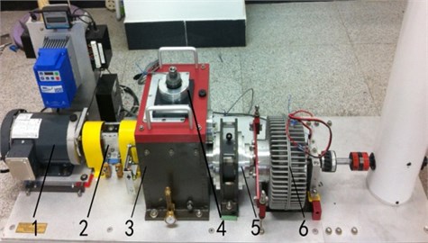
Fig. 12 shows a multistage gear transmission test rig consisting of a two-stage fixed-axis gear and an one-stage planetary gear.
Fig. 12The test rig of multistage gear transmission system: 1 – motor, 2 – torque sensor and encoder, 3 – two stage fixed-axis gearbox, 4 – radial load of bearing, 5 – one stage planetary gearbox, 6 – brake
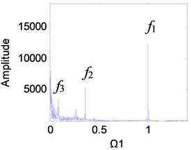
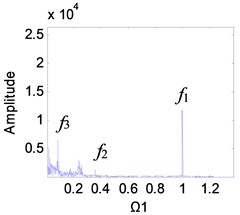
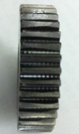
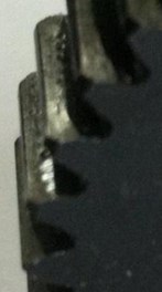
The planetary gear 1 in the test rig is the wear gear (see Fig. 13). It was found in 3.1 that the excitation frequency range affected by the planetary gear wear was [3, 4]. The closer the excitation frequency is to the region, the more obvious the vibration characteristics of the planetary gear are. In order to identify changes in the planetary gear wear signals, the excitation frequency was varied by adjusting the motor speed of the test rig. Since the maximum speed of the test rig is 3000 rpm, the signals were tested and analyzed with the motor speed of 1800 rpm (corresponding to the excitation frequency 1) and 2400 rpm (corresponding to the excitation frequency 1.5). In order to compare the measured spectrums with the dimensionless simulation results, the dimensionless spectrums of the vertical direction of the planetary gearbox at different speed were obtained in Fig. 14. The dimensionless characteristic frequencies of each stage gears of the multi-stage gear transmission system is shown in Table 3.
Fig. 13Wear planetary gear
a)
b)
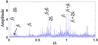
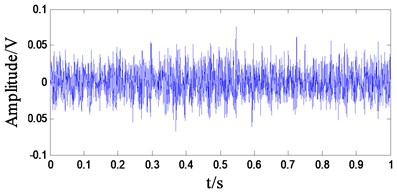
As can be seen from Fig. 14(b), planetary gear meshing frequency is not significant when the excitation frequency is low. As the excitation frequency increases (Fig. 14(d)), planetary gear meshing frequency amplitude increases. This conclusion is consistent with the numerical simulation result, indicating that the planetary gear has obvious vibration characteristics at high excitation frequency. It can be seen from the numerical simulation results that the increase of the planetary gear wear will increase the amplitude of the meshing frequency of the planetary gear and its higher harmonics but will not generate other side frequency components. Through the variation of the amplitude of the planetary gear meshing frequency, the numerical simulation results were used to identify the planetary gear wear.
Fig. 14Comparison of spectrum of the planetary gearbox at different speeds: a) motor speed 1800 rpm time-domain, b) motor speed 1800 rpm frequency-domain, c) motor speed 2400 rpm time-domain, d) motor speed 2400 rpm frequency-domain
a)
b)
c)
d)
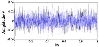
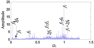
Comparing the theoretical simulation results with the experimental results, the main frequency components are compared in detail. A comparison is drawn between Fig. 10(a) and Fig. 14(b) in which the excitation frequency is the same as 1. Because of the different amplitudes of the two, for the sake of comparison, the magnitude of the dimensionless spectrum of the theoretical simulation is scaled down, as shown in Fig. 15.
Fig. 15Comparison of main frequency between theoretical and experimental results
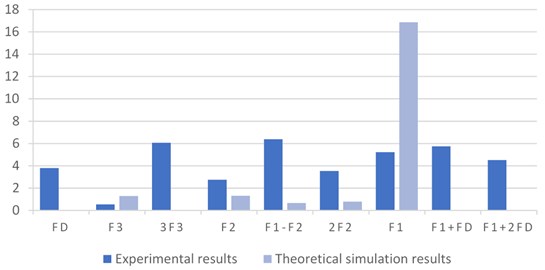
As can be seen from Fig. 15, peak values of , , , 2 and - are all found in both theoretical and experimental conclusions. The difference is that there is a lack of peaks associated with in the theoretical value. This is because the established stiffness and error models are functions of the meshing frequency, ignoring the motor frequency . In the ratio of the energy of the frequency components, in the theoretical value is much larger than other frequency components. In the experimental values, the frequency components are proportionally balanced, and when the rotational speed is increased, the peak is highlighted (Fig. 14(d)).
5. Conclusions
In this paper, the nonlinear dynamic characteristics of the wear of planetary gear in a multistage gear transmission system were studied. Planetary gear wear was simulated through the change of the planetary gear clearance, and the bifurcation diagrams of the fixed-axis gear and planetary gear under different clearances were analyzed. The changes of the system's motion state were investigated. The vibration mechanism of the system with wear failure was summarized. The study found that the wear of the planetary gear mainly affected the excitation frequency range of [3, 4]. As the excitation frequency increased, the motion state of the system changed from periodic motion to quasi-periodic motion. The wear caused the excitation frequency of the system to enter the quasi-periodic motion to advanced. By studying the time-domain, frequency-domain, phase diagram and Poincaré section of each motion state of the fixed-axis gear and planetary gear under different clearances, the transition processes and frequency characteristics of each motion state were analyzed. Frequency characteristics of wear were obtained.
The vibration signals of the experimental rig were tested at different excitation frequencies. When the rotational speed was increased, the amplitude of the meshing frequency of the planetary gear increased. This result is the same as the theoretical study.
References
-
Kuang J. H., Lin A. D. The effect of tooth wear on the vibration spectrum of a spur gear pair. Journal of Vibration and Acoustics, Vol. 123, Issue 3, 2001, p. 311-317.
-
Yuksel C., Kahraman A. Dynamic tooth loads of planetary gear sets having tooth profile wear. Mechanism and Machine Theory, Vol. 39, Issue 7, 2004, p. 695-715.
-
Wojnarowski J., Onishchenko V. Tooth wear effects on spur gear dynamics. Mechanism and Machine Theory, Vol. 38, Issue 2, 2003, p. 161-178.
-
Li S., Kahraman A. A micro-pitting model for spur gear contacts. International Journal of Fatigue, Vol. 59, Issue 2, 2014, p. 224-233.
-
Brand J. A., Martins R., Seabra J. H. O., et al. An approach to the simulation of concurrent gear micropitting and mild wear. Wear, Vol. 324, 2015, p. 64-73.
-
Zhang Y. C., Tian H. Q., Tang J. Y., et al. Study on sliding wear of high pair based on friction work principles. China Mechanical Engineering, Vol. 3, 2010, p. 344-347.
-
He R. G., Jian Q. Y., Yao Y. F. Numerical simulation of tooth wearing for involute helical cylindrical gears. Lubrication Engineering, Vol. 32, Issue 3, 2007, p. 88-91.
-
Liu Z. X., Liu Z. S., Zhao J. M., Zhang G. H. Study on interactions between tooth backlash and journal bearing clearance nonlinearity in spur gear pair system. Mechanism and Machine Theory, Vol. 107, 2017, p. 229-245.
-
Ding H. L., Kahraman A. Interactions between nonlinear spur gear dynamics and surface wear. Journal of Sound and Vibration, Vol. 307, Issue 3, 2007, p. 662-679.
-
Onishchenko V. Investigation of tooth wears from scuffing of heavy duty machine spur gears. Mechanism and Machine Theory, Vol. 83, 2015, p. 38-55.
-
Shen Y. J., Yang S. P., Xing H. J., Wang X. Y. Nonlinear dynamics of a spur gear pair with fault. Key Engineering Materials, Vol. 84, Issue 353, 2007, p. 1177-1180.
-
Liu X., Yang Y., Zhang J. Investigation on coupling effects between surface wear and dynamics in a spur gear system. Tribology International, Vol. 101, 2016, p. 383-394.
-
Priest M., Taylor C. M. Automobile engine tribologyapproaching the surface. Wear, Vol. 241, Issue 2, 2000, p. 193-203.
-
Feng S., Fan B., Mao J., et al. Prediction on wear of a spur gearbox by on-line wear debris concentration monitoring. Wear, Vol. 336, 2015, p. 1-8.
-
Wu H., Kwok N. M., Liu S., et al. A prototype of online extraction and three-dimensional characterisation of wear particle features from video sequence. Wear, Vol. 368, 2016, p. 314-325.
-
Hu C., Smith W. A., Randall R. B., et al. Development of a gear vibration indicator and its application in gear wear monitoring. Mechanical Systems and Signal Processing, Vol. 76, Issue 77, 2016, p. 319-336.
-
Zhang R., Gu F., Mansa H., et al. Gear wear monitoring by modulation signal bispectrum based on motor current signal analysis. Mechanical Systems and Signal Processing, Vol. 94, 2017, p. 202-213.
-
He Q. B. Time-frequency manifold for nonlinear feature extraction in machinery fault diagnosis. Mechanical Systems and Signal Processing, Vol. 35, Issues 1-2, 2013, p. 200-218.
-
Wang X. Stability research of the planetary multi-stage gear transmission system with coupling faults. Journal of Sound and Vibration, Vol. 434, 2018, p. 63-77.
-
Flodin A., Andersson S. Simulation of mild wear in spur gears. Wear, Vol. 207, Issue 2, 1997, p. 16-23.
-
Park D., Kolivand M., Kahraman A. An approximate method to predict surface wear of hypoid gears using surface interpolation. Mechanism and Machine Theory, Vol. 71, 2014, p. 64-78.
-
Wang Y. G., Zheng H. Q., Yang T. Q., Guan Z. Z., Yang J. Nonlinear dynamics behavior of gear system with fault parameters. Journal of Vibration, Measurement and Diagnosis, Vol. 31, Issues 5-2011, 570, p. 573-662.
-
Wang X., Xu Y. X., Wu B. L. Study on failure characteristics of gearbox transmission system with coupling faults. Journal of Vibration and Shock, Vol. 36, Issue 12, 2017, p. 217-223.
Cited by
About this article

This research is supported by Baoji Municipal Science and Technology Bureau (2017JH2-11), China.
