Abstract
This paper proposes a method of analyzing distinct modal characteristics to obtain accurate sensitivity of natural frequencies and coupled modes to system parameters of multi-stage planetary gears. A purely rotational dynamic model of multi-stage planetary gear system with general descriptions is established based on the lumped mass method. The vibration modes of multi-stage planetary gears are classified into overall and planet modes with unique properties. According to the modal energy distributions in multi-stage planetary gears, the natural frequencies are clustered by each dominant vibration stage. The modal properties of each cluster in the multi-stage planetary system are similar to the single-stage planetary gear system established by the associated dominant vibration stage. It is shown that, variation of gear parameters in one planet stage mainly affects the natural frequencies in the cluster associated with the same stage, while the coupling shaft parameters significantly impact the natural frequencies corresponding to the planet stage which contains the connected sun gear.
1. Introduction
Multi-stage planetary gears are widely used in many applications such as automobiles, helicopters and tunneling boring machine (TBM) due to their advantages of high power density and large reduction in a small volume [1]. The vibration and noise problems of multi-stage planetary gears are always the focus of attention by both academics and engineers [2].
The vibration of simple, single-stage planetary gears has been studied by many researchers. In the early literatures [3-5], the vibration structure of some example planetary gears are identified using lumped-parameter models, but they didn’t give general conclusions. Lin and Parker [6-7] formally identified and proved the vibration structure of planetary gears with equal/unequal planet spacing. They analytically classified all planetary gears modes into exactly three categories, rotational, translational, and planet modes. Parker [8] also investigated the clustering phenomenon of the three mode types. In the recent literatures, the systematic classification of modes were carried into systems modeled with an elastic continuum ring gear [9], helical planetary gears [10], herringbone planetary gears [11], and high speed gears with gyroscopic effects [12].
The natural frequencies and vibration modes of multi-stage planetary gears have also received attention. Kahraman [13] established a family of torsional dynamics models for compound planetary gears under different kinematic configurations. Kiracofe [14] developed a dynamic model of compound planetary gears of general description including translational degrees of freedom, which allows an infinite number of kinematic combinations. They mathematically proved that the modal characteristics of compound planetary gears were analogous to a simple, single-stage planetary gear system. Meanwhile, there are many researchers focusing on the nonlinear dynamic characteristics of the multi-stage planetary gears for engineering applications, such as TBM [15] and wind turbine [16].
According to the aforementioned models and vibration structure of planetary gears, many researchers concerned the sensitivity of the natural frequencies and vibration modes to system parameters. They investigated the effect of modal parameters such as tooth mesh stiffness, planet bearing stiffness and support stiffness on planetary gear natural frequencies and vibration modes [17-19]. Parker et al. [20-21] mathematically analyzed the effects of design parameters on natural frequencies and vibration modes both for the single-stage and compound planetary gears. They proposed closed-form expressions for the eigensensitivities to model parameter variations according to the well-defined vibration mode properties, and established the relation of eigensensitivities and modal energies. Lin and Parker [22] investigated the veering of planetary gear eigenvalues. They used the structured vibration modes to show that eigenvalue loci of different mode types always cross and those of the same mode type veer as a model parameter is varied.
However, most of the current studies only referenced the method used for single-stage planetary gears to analyze the modal characteristics of multi-stage planetary gears, while the differences between these two types of planetary gears were ignored. Because of the multiple degrees of freedom in multi-stage planetary gears, more detailed division of natural frequencies are required to analyze the influence of different system parameters. The objective of this paper is to propose a novel method of analyzing the coupled modes in multi-stage planetary gears to analyze the parameter sensitivities. Purely rotational degree of freedom models are used to simplify the analytical investigation of gear vibration while keeping the main dynamic behavior generated by tooth mesh forces. In this paper, sensitivity of natural frequencies and vibration modes to both gear parameters and coupling shaft parameters of multi-stage planetary gears are studied.
2. Purely rotational model of multi-stage planetary gear
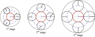
The multi-stage planetary gear system focused in this paper is created by joining multiple planet stages together, where each stage can be considered as a simple planetary. Fig. 1(a) shows an example three-stage planetary gear system used in the driving system of TBM [23]. The purely rotational model is shown in Fig. 1(b). Each carrier, ring, sun, and planet has a single rotational degree of freedom. All external supports and shaft connections are modeled as linear torsional stiffnesses. The interactions between carrier and planets in each stage are considered as rigid connections. The gear mesh interactions are represented by linear springs acting along the line of action.
Fig. 1The example three-stage planetary system
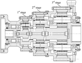
a) Structural model
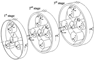
b) Equivalent dynamic model
In Fig. 1(b), all components are described in a single fixed basis with the origin on the rotation center of carrier in the first stage. In each planet stage, the rotational coordinate are , , , , ,…, , where is the component rotation, is the base circle radius for sun, ring and planet, the radius of circle passing through the planet centers for the carrier.
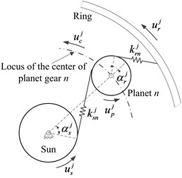
The gear mesh is modeled as a spring-damper element acting along the line of action [24] in Fig. 1(b), where the damper is not described due to the same action line as the spring. The deflection of the -th sun-planet mesh and ring-planet mesh shown in Fig. 2 are:
where, and are the sun-planet and ring-planet operating pressure angles.
The coupling interaction between sun and the carrier in two connected planet stages is:
Taking into account the Lagrange formalism, the differential equation of motion of the multi-stage planetary gear system can be expressed by:
where is the mass matrix, is the damping matrix, is the symmetric stiffness matrix from both bearing support and haft couplings, is the stiffness matrix from tooth meshes, and is the vector of applied torques. The vector and matrix components are:
details of the sub-matrices in , and are given in Appendix.
Fig. 2The model of sun-planet and ring-planet mesh in the j-th planet stage
3. Characteristics of natural frequencies and vibration modes
To determine the natural frequencies and vibration modes, the time-invariant system is considered. All mesh stiffness are considered to be constant and equal to their average value over one mesh cycle. The damping matrix is ignored in the modal analysis. Thus, the associated eigenvalue problem is:
where is the natural frequency, and is the vibration modes with the form:
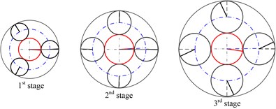
In each planet stage, all planets are assumed equally spaced and have identical model parameters. According to these assumptions, the multi-stage planetary gears become a cyclically symmetric structure. Table 1 lists the main system parameters [23]. The system has 20 degrees of freedom. Using numerical method, the natural frequencies and vibration modes can be calculated. All vibration modes for the system can be classified into one of two types: overall modes and planet modes.
Table 1Parameters of the example system
Parameters | Sun | Ring | Carrier | Planet | ||||||||
1th | 2nd | 3rd | 1th | 2nd | 3rd | 1th | 2nd | 3rd | 1th | 2nd | 3rd | |
Mass (kg) | 4.2 | 8.8 | 24.6 | 30.7 | 62.6 | 93.5 | 17.7 | 38.9 | 93 | 1.6 | 2.9 | 8.7 |
(kg) | 1.7 | 3.8 | 12.6 | 50.4 | 94.2 | 145 | 18.1 | 38.7 | 89.8 | 1.1 | 2.1 | 6.8 |
Base diameter (mm) | 47 | 63.4 | 67.7 | 122 | 162 | 203 | 91 | 121 | 145 | 37.6 | 49.4 | 67.7 |
Mesh stiffness (N/m) | 3.8×10⁸, 5.4×10⁸, 7×10⁸ | |||||||||||
Torsional stiffness (N/m) | 0, 1×10⁹, 0, 1, 2, 3 | |||||||||||
Coupling stiffness (N/m) | ||||||||||||
Pressure angle | 21.7°, 21.3°, 21.1° | |||||||||||
Planet number | 3, 4 | |||||||||||
3.1. Overall modes
Each overall mode is associated with a distinct natural frequency. There are exactly overall modes. In a rotational mode, all planets in the same planet stage have identical motions. Fig. 3 shows a typical overall mode for the example system. A candidate overall mode form is:
Fig. 3A typical overall mode (ω7= 2160.8 Hz) of the example system
3.2. Planet modes
Planet modes exist when the system has a stage with two or more planet gears. Stage has one degenerate planet modes with natural frequency multiplicity (). In a planet mode, only the planets in one stage have motion, and all other components have no motion. In addition, any planet motion in one stage is a scalar multiple of an arbitrarily chosen planet’s motion. Fig. 4 shows a typical planet mode for the example system. A candidate planet mode associated with stage is:
Fig. 4A typical planet mode (ω12= 3609.3 Hz) of the example system
4. Natural frequency distribution of multi-stage planetary gears
Considering the typical overall mode shown in Fig. 3, a phenomenon can be observed that there is one dominant vibration stage with the highest vibration amplitude, while the component motions of the other stages decrease along the neighboring relation gradually. Meanwhile, according to the properties of planet modes, only the planets in one stage have motion. Therefore, it is possible to distinguish the dominant vibration stage in each vibration mode.
4.1. Modal energy distribution
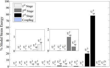
Cunliffe [3] originally observed that the natural frequency in a single-stage planetary gear system can be divided into different bands by comparing the modal energy distributions, and Parker [25] described this phenomenon in detail using experimental setup. Table 2 lists the expressions of modal strain and kinetic energies in vibration mode . The subscripts and superscripts have the same meanings as for stiffness parameters. For example, means the modal kinetic energy of carrier in planet stage .
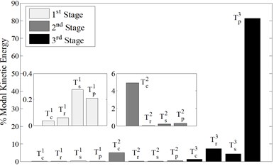
Fig. 5 illustrates the modal (a) strain energy and (b) kinetic energy distributions in a typical overall mode (2160.8 Hz). Both of the modal strain and kinetic energy reach highest at the 3rd stage, which matches the feature of overall mode shown in Fig. 3. So it is possible to distinguish the dominant vibration stage by comparing the energy distributions in each mode. Without loss of generality, the modal kinetic energy is chosen in this paper.
Table 2The expressions of modal strain and kinetic energies in vibration mode ϕv associated with frequency ωv
Modal strain energy | Modal kinetic energy |
Fig. 5Modal a) strain and b) kinetic energy distributions associated with mode 7 (ω7= 2160.8 Hz)
a)
b)
4.2. Natural frequency distribution
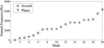
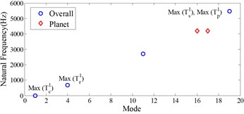
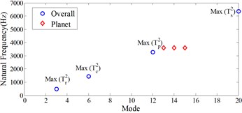
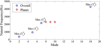
Comparing the modal kinetic energies of each planet stage in each vibration mode, the planet stage with highest modal kinetic energy is marked as the dominant vibration stage. Fig. 6(a) shows the integrated natural frequencies of the example multi-stage planetary gears shown in Fig. 1 with parameters list in Table 1. Gathering the natural frequencies with the same dominant vibration stage, the integrated natural frequencies of the example system are classified into three categories, which are shown in Fig. 6(b)-(d). There are two mode types of frequency appearing in each category consistently, and the number of natural frequencies in each mode type are similar to each individual single-stage planetary gear system.
Meanwhile, comparing the modal kinetic energy of each component among all of the vibration modes, almost each maximum modal kinetic energy corresponds to a different natural frequency, which is marked in Fig. 6(b)-(d). As an exception, the maximum modal kinetic energies of the sun gear and planet gears in the 1st stage simultaneously correspond to , while there is no maximum modal kinetic energy corresponding to . However, the component which has the maximum modal kinetic energy corresponding to one natural frequency, just belongs to the dominant vibration stage of the assigned frequency dramatically.
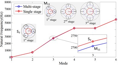
Fig. 7 shows the comparative results of natural frequencies and vibration modes between the example multi-stage planetary gear system and three individual single-stage planetary gear systems with the parameters list in Table 1. All the planet mode frequencies of single-stage and multi-stage planetary gear system are equivalent, while the overall mode frequencies are approximate to each other. In the zoomed view, the overall mode frequencies of multi-stage planetary gear system with dominant vibration of the 1st stage are smaller than the single-stage system, while the opposite phenomenon is observed in the 2nd stage and the 3rd stage, where the frequencies of single-stage planetary gear system are larger. The frequency gap between the single-stage and multi-stage planetary gear system are larger in the 2nd stage and the 3rd stage. Focusing on the motions of dominant vibration stage in each mode of the multi-stage planetary gears, they are similar to the mode of the individual single-stage planetary gears at the corresponding natural frequency.
Fig. 6Natural frequency distributions of the example multi-stage planetary gear system, a) total natural frequencies, b)-d) the natural frequencies with dominant vibration motions in b) 1st stage, c) 2nd stage, d) 3rd stage
a)
b)
c)
d)
Fig. 7Comparison of the natural frequencies and vibration modes between the single-stage and multi-stage planetary gear system
a) 1st stage
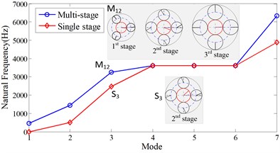
b) 2nd stage
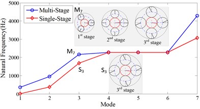
c) 3rd stage
Overall, according to the modal kinetic energy distribution, the natural frequencies in multi-stage planetary gears are classified by the dominant vibration stage. Using this classification method, the similarities of natural frequencies and vibration modes between multi-stage and single-stage planetary gears are detected.
5. Sensitivity of natural frequencies to model parameters
The eigenvalue sensitivities of multi-stage planetary gears to modal parameters can be deduced by the unique modal properties listed in Eqs. (10) and (11). According to the expression of modal strain and kinetic energies shown in Table 2, the compact closed-form formulas of eigensensitivities [21] to modal parameters are listed as follows.
Eigenvalue sensitivity to mesh stiffness:
Eigenvalue sensitivity to torsional stiffness:
Eigenvalue sensitivity to shaft stiffnesses between carriers and suns in different planet stages:
Eigenvalue sensitivity to moments of inertia:
Eqs. (12)-(16) allow one to obtain the natural frequency sensitivity to system parameters by inspection of the modal strain and kinetic energy distribution. Recalling the planet mode property described in Eq. (11), planet modes are insensitive to both stiffnesses and moments of inertia of the carriers, rings, and suns, while they are only sensitive to the planet parameters of their associated planet stage.
5.1. Sensitivity to gear parameters
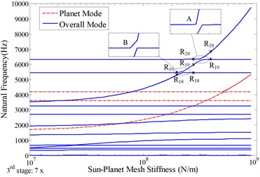
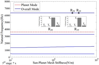
Fig. 8 and Fig. 9 show the sensitivity of natural frequencies in the example multi-stage planetary system to variation in mean sun-planet mesh stiffness. Fig. 8 only considers variation in the stiffness of the 3rd stage, while Fig. 9 shows natural frequency sensitivity to the variations in the stiffness of all the three stages. The variation in mean mesh stiffness is considered across two orders of magnitude, and the nominal value from Table 1 is signed at the horizontal center in each graph. Similar results will be obtained by varying the mean ring-planet mesh stiffness.
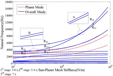
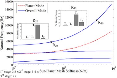
In Fig. 8(a), the natural frequency loci of the example multi-stage planetary gears are classified by two mode types, overall mode and planet mode, which are plotted by different line styles. As the mean sun-planet mesh stiffness being varied, the frequencies over 2000 Hz are observed more sensitivity to the change of mesh stiffness. Veering phenomenons occur when two overall/planet mode frequency loci approach each other, but then abruptly veer away. According to the natural frequency plots, when the mean sun-planet mesh stiffness varied in 1.4e9-2.8e9 (N/m), twice veering phenomena (A and B) occur among the overall mode frequency loci R18, R19 and R20, where the subscript means the modal ordinal.
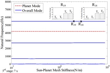
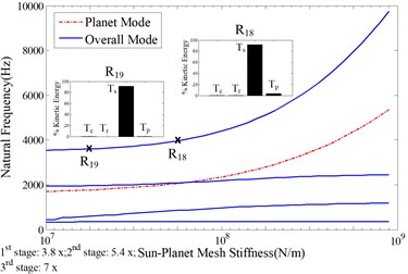
Classifying the overall/planet frequency loci by the dominant vibration stage, the natural frequency plots of each associated planet stage are shown in Fig. 8(b)-(d) respectively. Only the natural frequency associated with the 3rd stage shows significant change versus the variation of mean sun-planet mesh stiffness of the 3rd stage, while the other natural frequency loci almost keep straight. In Fig. 8(b)-(d), the modal kinetic energy distributions of the frequency points besides veering points A and B shown in Fig. 8(a) are observed keeping consistent along each natural frequency locus, which indicates that the modal properties of the veering modes are exchanged across the veering zones in Fig. 8(a). In other words, it was due to the variation of the modal energy distributions that led to the modal veering phenomenon happened. In the veering zone, even a slight variation in the stiffness parameter can also lead to great changes in the vibration modes, which will significantly affect the dynamic characteristics of system. Consequently, these parameter areas should be avoided in the design process.
Fig. 8Sensitivity of natural frequencies to the mean sun-planet mesh stiffness in the 3rd stage with the nominal value indicated in Table 1, a) total natural frequencies; b)-d) the natural frequencies with dominant vibration motions in b) 1st stage, c) 2nd stage, d) 3rd stage
a)
b)
c)
d)
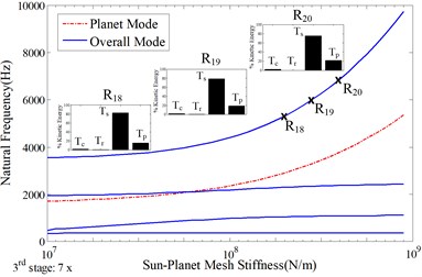
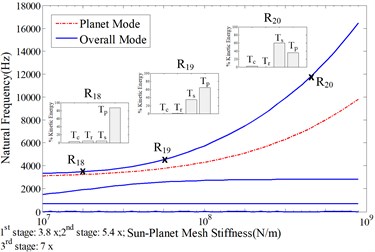
In Fig. 9(a), as the mean sun-planet mesh stiffness of all the three stages being increased simultaneously, the natural frequency values grow more rapidly, which result in more veering phenomena. In Fig. 9(b)-(d), the natural frequency associated with each planet stage shows high sensitivity to the change of mean mesh stiffness. There are some variation of the modal kinetic distributions along one natural frequency loci. However, the veering phenomena also occur in the natural frequencies associated with the same dominant vibration, especially in the 1st stage, which is shown in Fig. 9(b).
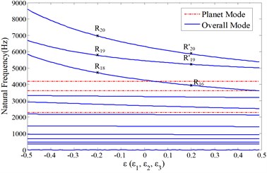
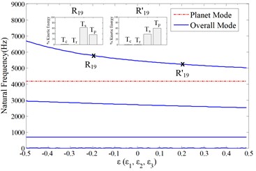
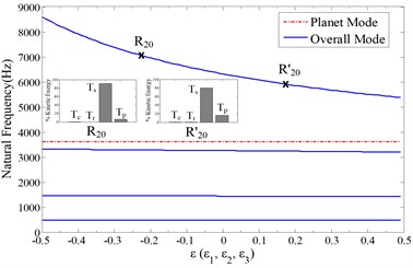
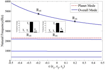
Fig. 10 shows the sensitivity of natural frequencies in the example multi-stage planetary system to the variation in the sun moment of inertias of all the three stages. According to Eq. (11), the overall mode frequencies decline as the sun moment of inertias increase, while the planet mode frequencies remain consistent. It is shown in Fig. 10(a). Choosing the rapidly declining frequency loci in Fig. 10(b)-(d) as example, the modal kinetic energy distributions are exhibited small change along each natural frequency locus.
Fig. 9Sensitivity of natural frequencies to the mean sun-planet mesh stiffness in all of the three stages with the nominal value indicated in Table 1, a) total natural frequencies; b)-d) the natural frequencies with dominant vibration motions in b) 1st stage, c) 2nd stage, d) 3rd stage
a)
b)
c)
d)
Overall, the gear parameter variation in one arbitrary planet stage would mainly affect the natural frequencies associated with this given stage, while it plays small effect on the other natural frequencies.
5.2. Sensitivity to coupling shaft parameters
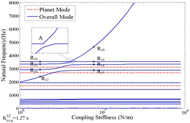
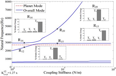
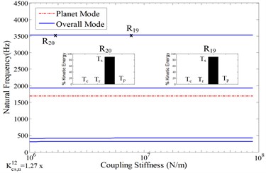
Fig. 11 shows the sensitivity of natural frequencies in the example multi-stage planetary system to the stiffness of coupling shaft connecting the 1st stage and the 2nd stage. Similar to Fig. 8 and Fig. 9, the variation in coupling stiffness is considered across two orders of magnitude with the nominal values from Table 1. In Fig. 11(a), only the plots of overall mode natural frequencies vary with the occurrence of veering phenomena as the coupling stiffness is being changed.
According to the overall/planet mode frequency loci distinguished by dominant vibration stage shown in Fig. 11(b)-(d), the overall mode frequencies associated with the 2nd stage are shown high sensitive to the coupling stiffness. This phenomenon can be explained that the 2nd stage contains the connected sun gear, and the eigensensitivity to sun parameters reaches highest in the high frequency region, which is shown in Fig. 6.
Fig. 10Sensitivity of natural frequencies to the sun moment of inertia in all of the three stages with the nominal value indicated in Table 1, ε=(Isj-I-sj)/I-sj. Isj and I-sj are the nominal and perturbed values of sun moment of inertia in the j-th planet stage. a) total natural frequencies; b)-d) the natural frequencies with dominant vibration motions in b) 1st stage, c) 2nd stage, d) 3rd stage
a)
b)
c)
d)
Fig. 11Sensitivity of natural frequencies to the stiffness of the coupling shaft connecting the 1st stage and the 2nd stage with the nominal value indicated in Table 1, a) total natural frequencies; b)-d) the natural frequencies with dominant vibration motions in b) 1st stage, c) 2nd stage, d) 3rd stage
a)
b)
c)
d)
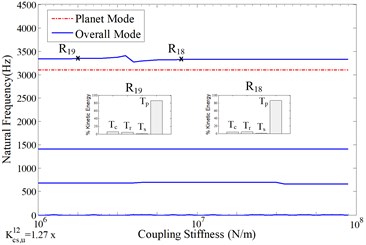
However, the veering phenomenon of the overall mode frequency loci associated with the 2nd stage occur when the coupling stiffness value is near 4.02e6 (N/m). In Fig. 11(b), the overall mode frequency loci associated with the 1st stage are shown little sensitive to the change of coupling stiffness between the 1st and the 2nd planet stage. Comparing the frequency points beside the veering point A in Fig. 11(a) which are fallen in the same frequency locus in Fig. 11(b), the frequency R18 is little small than R19, and this phenomenon is consistent with the conclusion from Fig. 7(a).
6. Conclusions
1) A purely rotational dynamic model is established for the general multi-stage planetary gear system. All vibration modes of the system fall into the categories of overall and planet modes. Only one planet stage of planets exists as motions in the planet modes.
2) The natural frequencies in multi-stage planetary gears are clustered by their dominant vibration stages, which are distinguished by comparing the modal energy distributions. The modal properties such as frequency classification and vibration modes of each cluster in the multi-stage planetary system are similar to the single-stage planetary gear system established by the associated dominant vibration stage.
3) The planet mode frequencies are only sensitive to the mesh stiffnesses and the parameters of planet gears. The variation of gear parameters in one planet stage mainly affects the natural frequencies in the cluster associated with the same stage, while they play very little influence on the other frequencies. Coupling shaft parameters significantly impact the natural frequencies corresponding to the planet stage which contains the connected sun gear.
7. Appendix
The sub-matrices of in Eq. (4) are:
The sub-matrices of , in Eq. (5) are:
References
-
Lynwander P. Gear Drive Systems: Design and Application. New York, Marcel Dekker, 1983.
-
Smith J. D. Gear Noise and Vibration. New York, Marcel Dekker, 2003.
-
Cunliffe F., Smith J. D., Welbourn D. B. Dynamic tooth loads in epicyclic gears. Journal of Engineering for Industry, Vol. 5, 1974, p. 578-584.
-
Botman M. Epicyclic gear vibrations. Journal of Engineering for Industry, Vol. 98, Issue 3, 1976, p. 811-815.
-
Kahraman A. Planetary gear train dynamics. Journal of Mechanical Design, Vol. 116, Issue 3, 1994, p. 713-720.
-
Jian L., Parker R. G. Analytical characterization of the unique properties of planetary gear free vibration. Journal of Vibration and Acoustics, Vol. 121, Issue 3, 1999, p. 316-321.
-
Jian L., Parker R. G. Structured vibration characteristics of planetary gears with unequally spaced planets. Journal of Sound and Vibration, Vol. 233, Issue 5, 2000, p. 921-928.
-
Ericson T. M., Parker R. G. Natural frequency clusters in planetary gear vibration. Journal of Vibration Acoustics, Vol. 135, Issue 6, 2013, p. 061002-1-13.
-
Wu X., Parker R. G. Modal properties of planetary gears with an elastic continuum ring gear. Journal of Applied Mechanics, Vol. 75, Issue 3, 2008, p. 031014-1-12.
-
Eritenel T., Parker R. G. Modal properties of three-dimensional helical planetary gears. Journal of Sound and Vibration, Vol. 335, Issue 1, 2009, p. 397-420.
-
Bu Z., Liu G., Wu L. Modal analyses of herringbone planetary gear train with journal bearings. Mechanism and Machine Theory, Vol. 54, 2012, p. 99-115.
-
Cooley C. G., Parker R. G. Vibration properties of high-speed planetary gears with gyroscopic effects. Journal of Vibration and Acoustics, Vol. 134, Issue 6, 2012, p. 061014-1-13.
-
Kahraman A. Free torsional vibration characteristics of compound planetary gear sets. Mechanism and Machine Theory, Vol. 36, 2001, p. 953-971.
-
Kiracofe D., Parker R. G. Structured vibration modes of general compound planetary gear systems. Journal of Vibration and Acoustics, Vol. 129, Issue 1, 2007, p. 1-16.
-
Wei J., Sun Q. C., Sun W., et al. Load-sharing characteristic of multiple pinions driving in tunneling boring machine. Chinese Journal of Mechanical Engineering, Vol. 26, Issue 3, 2013, p. 532-540.
-
Helsen J., Vanhollebeke F., Marrant B., et al. Multibody modelling of varying complexity for modal behaviour analysis of wind turbine gearboxes. Renewable Energy, Vol. 36, Issue 1, 2011, p. 3098-3113.
-
Saada A., Velex P. An extended model for the analysis of the dynamic behavior of planetary trains. Journal of Mechanical Design, Vol. 117, Issue 2, 1995, p. 241-247.
-
Kahraman A. Natural modes of planetary gear trains. Journal of Sound and Vibration, Vol. 173, Issue 1, 1994, p. 125-130.
-
Velex P., Flamand L. Dynamic response of planetary trains to mesh parametric excitations. Journal of Mechanical Design, Vol. 118, Issue 1, 1996, p. 7-14.
-
Lin J., Parker R. G. Sensitivity of planetary gear natural frequencies and vibration modes to model parameters. Journal of Sound and Vibration, Vol. 228, Issue 1, 1999, p. 109-128.
-
Guo Y. C., Parker R. G. Sensitivity of general compound planetary gear natural frequencies and vibration modes to model parameters. Journal of Vibration Acoustics, Vol. 132, Issue 1, 2010, p. 011006.
-
Lin J., Parker R. G. Natural frequency veering in planetary gears. Mechanics of Structures and Machines, Vol. 29, Issue 4, 2001, p. 411-429.
-
Qin D. T., Xiao Z. M., Wang J. H. Dynamic characteristics of multi-stage planetary gears of shield tunneling machine based on planet mesh phasing analysis. Journal of Mechanical Engineering, Vol. 47, Issue 23, 2011, p. 20-29.
-
Guo Y. C., Parker R. G. Purely rotational model and vibration modes of compound planetary gears. Mechanism and Machine Theory, Vol. 45, Issue 3, 2010, p. 365-377.
-
Ericson T. M., Parker R. G. Planetary gear modal vibration experiments and correlation against lumped-parameter and finite element models. Journal of Sound and Vibration, Vol. 332, Issue 9, 2013, p. 2350-2375.
About this article

The authors would like to acknowledge the support and contributions from the School of Mechanical Engineering, Dalian University of Technology, China. The research is supported by National Basic Research Program of China (973 Program, Grant No. 2013CB035402) and the Fundamental Research Funds for Central Universities (No.106112015CDJXY110001).
