Abstract
In the multistage gear transmission system, when multiple faults are coupled, the faults with weak signals are often hidden and hard to identify. Multi-fault coupling may also cause new coupling fault characteristics, such as new peaks or side bands in the spectrum. These characteristics are likely to contain fault information. Studying the sources of frequency components in coupled fault signals will help to decouple the signals and dig out the correlation characteristics between faults. The coupling fault of fixed-axis gear crack and planetary gear tooth broken was studied in this paper. The nonlinear dynamic model of the multi-stage gear transmission system was used for simulation, and the fault frequency characteristics of the system varying with the excitation frequency were obtained. The short-time Fourier transform (STFT) and waterfall plot analysis were applied to the experimental signals to separate the fault features. By comparing the theoretical and experimental signals, we found the natural frequency of the system, the side frequency characteristics of single fault and coupling fault, and the cause of new peaks. This study has a guiding significance for the separation and identification of coupling faults of the multi-stage gear transmission system.
Highlights
- The nonlinear dynamic model of the multi-stage gear transmission system is used for simulation, and the fault frequency characteristics of the system varying with the excitation frequency are obtained.
- By analyzing the bifurcation diagram of the multi-stage gear transmission system under single and coupled fault, the influence of coupling fault on the motion state of the system can be found.
- The correlation between faults can be found by studying the time-frequency vibration characteristics of each motion state.
- STFT and waterfall plot analysis are applied to the experimental signals to separate the fault features. The natural frequency of system, the side frequency characteristics of faults, and the cause of new peaks are found.
1. Introduction
Gear transmission system is widely used in industrial field. Most of them appear in the combination form of multi-stage gear transmission. In the multi-stage gear transmission system, a variety of vibration characteristics are mixed together, which makes the vibration signal complex. The fixed axis gear feature with strong signal is coupled with the planetary gear feature with weak signal, which makes it difficult to identify the planetary gear feature. Among all the faults, the coupling fault of the two is undoubtedly the most difficult to distinguish. How to distinguish the two from each other in hybrid signals, that is, decoupling and identification of the coupling fault is a hot topic in recent years. When studying the fault characteristics of planetary gear in the past, the author found that the fault characteristics of planetary gears not only increase the amplitude of the meshing frequency itself, but also affect the amplitude of the meshing frequency and sidebands of other gears. This shows that the coupling fault features are related. Therefore, the authors try to analyze and identify the two kinds of faults by studying the correlation of the coupling fault. Due to the influence of the nonlinear characteristics of the system, the strength of these correlations is not constant, but varies with the excitation frequency. Therefore, this paper will study the correlation characteristics of the coupling fault from a nonlinear perspective.
In order to identify the coupling fault in gear systems, most scholars use signal processing methods to filter and extract signal fault features. Wavelet packet, empirical mode decomposition and AR model are all commonly used methods. The combination of various methods is also a common way in recent years [1-5]. The law of coupling fault is not generally consistent. After filtering, there are still unrecognized fault features. Using machine learning [6, 7] method can bypass the vibration mechanism and directly classify coupling faults. Common classification methods include neural network [8], ant colony optimization algorithm [9], support vector machine [10], etc. Although the intelligent classifier [11] can well identify different composite fault modes. But the disadvantage of the existing intelligent algorithm is the lack of physical significance, in other words, it is difficult to understand how the neural network works [2]. Therefore, it is necessary to explore the vibration characteristics of coupling faults from the perspective of nonlinear dynamics.
In the field of nonlinear dynamic modeling of multi-stage gear system, the coupling fault models of unbalance, misalignment and friction [12] of double rotor system [13], rigidly coupled rotors system [14] and motor-flexible coupling-rotor system [15] have been established. For the dynamic study of coupling characteristics, the coupling vibration analysis of flexible structure of gear system [16], the dynamic coupling between time-varying meshing stiffness (TVM) and gear [17], strength coupling [18], and the nonlinear dynamic effect of clearance change on fault coupling [19] have been carried out. Some scholars also use finite element model [20] or vibration signal model [21] to simulate the coupling nonlinear dynamic characteristics and frequency spectrum characteristics of multi-stage gear transmission system. However, the researches on the nonlinear dynamic characteristics of multi-stage gear system and coupling faults are not perfect. The vibration characteristics of actual signals cannot be fully interpreted. Further research on fault vibration sources is needed.
In the past few decades, great progress has been made in the decoupling diagnosis of gearbox hybrid faults, but there is little research on the correlation of fault vibration sources [22]. The vibration signals excited by different components and/or faulty components are related to a certain extent. This dependence/correlation may have a significant impact on the results of fault diagnosis, leading to misdiagnosis or missed diagnosis [23]. Unfortunately, although there are often correlations in the actual mixed fault vibration signals, this problem has not been well studied in the composite fault decoupling diagnosis. Some experts try to use a parameter to quantify this correlation. Pearson correlation coefficient [24], correlation dimension [25-27] and wavelet correlation feature scale entropy [28] are proposed for fault classification. Vibration correlation analysis is also applied to propose a health parameter and establish a state assessment model [29]. Like the neural network, this intelligent classification algorithm with a single value lacks physical meaning. It is impossible to fundamentally determine the source of vibration. The correlation of fault vibration sources in hybrid faults will greatly increase the difficulty of fault detection. Therefore, it is very important to find out the vibration source, fault correlation and vibration mechanism. This paper will explore the fault correlation characteristics caused by the coupling fault from the perspective of nonlinear dynamics.
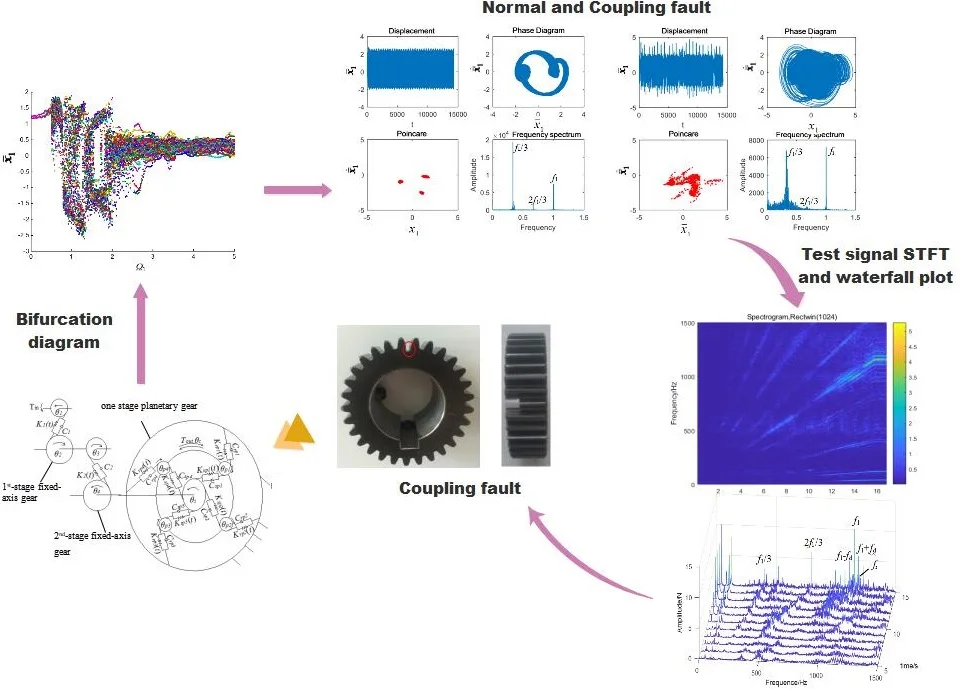
In this paper, a nonlinear dynamic model of the coupling fault including fixed axis gear crack fault and planetary gear tooth break fault was established. The simulation method was applied to compare and analyze the change of motion state of gear transmission system with the increase of excitation frequency under single fault and coupling fault conditions. The nonlinear and frequency characteristics of coupling fault under different motion states were solved. In order to compare the characteristics of different excitation frequencies in theoretical simulation, the experimental signals were analyzed by short-time Fourier transform and waterfall plot. Characteristic changes in the process of system speed up were summarized. The experimental results were compared with bifurcation diagrams and Poincaré sections to identify coupling fault and verify the simulation results. The vibration characteristics and correlation of coupling fault of multi-stage gear transmission system were obtained.
2. Torsional dynamic model of a multistage gear transmission system
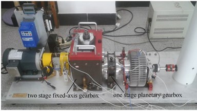
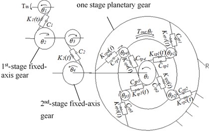
In this paper, the vibration test bench of the multi-stage gear transmission system shown in Fig. 1 is taken as the research object. The nonlinear dynamic model of multi-stage gear transmission system with fixed-axis gear crack fault and planetary gear tooth break fault was established and dimensionless. The specific modeling process has been deduced and elaborated in the author’s paper [19]. Only the final dimensionless differential equations of motion are listed here, that are Eq. (1):
where, is the time nominal scale, , . So dimensionless displacement is , (1, 2, , ). Dimensionless excitation frequency is , , (1, 2, , ). is the meshing frequency of each gear, (1, 2, , ). is the dimensionless excitation frequency of the 1st-stage fixed-axis gear. When 1, it is the critical speed.
The potential energy method [30] is used to calculate the tooth stiffness of the cracked gear. This method assumes that the meshing stiffness in the meshing gear pair includes four parts: Hertzian energy , bending energy , shear energy and axial compressive energy . The crack tooth model and calculation formula can be found in my paper [31]. In this paper, the crack is simulated as a straight line from the dangerous area of the gear tooth. The crack does not reach the center line, in which the crack length is 1 mm, and the angle between the crack line and the tooth center line is 70°. The 1st-stage fixed pinion (spur gear 1) has a crack fault. The cracked gear of the test bench is shown in Fig. 2.
Fig. 1Multistage gear transmission system: a) vibration test bench, and b) torsional dynamic model
a)
b)
Broken tooth planetary gear in the test rig is shown in Fig. 3. The fault feature is that the tooth width of the broken tooth changes whereas the other tooth width remains unchanged. The broken tooth length is 8 mm, and the remaining tooth width 12 mm. This characteristic is substituted into the calculation equations of bending energy, shear energy, axial compression energy and Hertzian energy in reference [30]. The fault stiffness of broken tooth of planetary gear is obtained. The gear parameters of the gear transmission system are shown in Table 1.
Fig. 2The fixed axis gear with crack
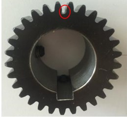
Fig. 3Planet gear with broken tooth
Table 1Gear parameters
Gear | Number of teeth | Mass / g | / (g·m2) | Face width /mm |
1 | 29 | 125 | 0.05 | 30 |
2 | 100 | 1224.5 | 6 | 30 |
3 | 36 | 224 | 0.14 | 30 |
4 | 90 | 1111 | 4 | 20 |
28 | 41 | 0.007 | 20 | |
36 | 34.6 | 0.01 | 20 | |
848.7 | 0.76 | 20 | ||
100 | 20 |
3. Nonlinear dynamic behavior analysis of the system with increased planetary gear wear
3.1. System bifurcation diagrams
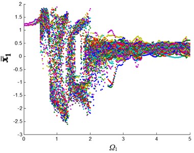
The variable step Runge-Kutta method was used to solve the nonlinear differential Eq. (1). The bifurcation diagrams of the system changing with excitation frequency under single fault and coupling fault were calculated. The structural parameters are shown in Tables 1 and 2. The vibration characteristic of the 1st-stage fixed-axis gear is more obvious. The crack fault is also added to its pinion. Therefore, the 1st-stage fixed-axis gear is selected as the research object. The bifurcation diagrams of its relative displacement with dimensionless excitation frequency are shown in Fig. 4.
Table 2Parameters of calculation
Parameters of calculation | Value |
Gear clearance (μm) | 3 |
Comprehensive meshing error amplitude (μm) | 5 |
Meshing pair damping ratio | 0.07 |
Gear contact ratio | 1.68 |
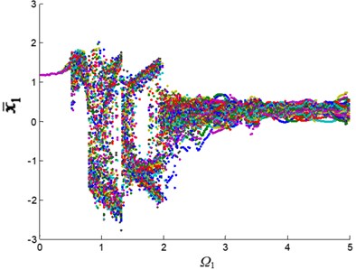
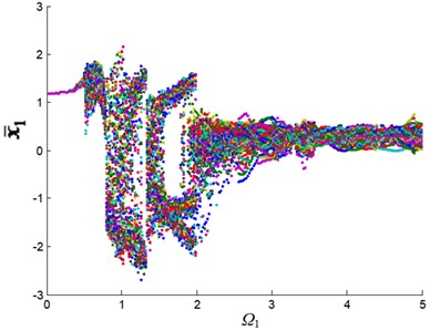
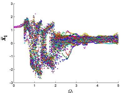
Fig. 4Displacement bifurcation diagram of the 1st-stage fixed-axis gear: a) normal state, b) planetary gear broken tooth fault state, c) fixed axis gear crack fault state, and d) two faults coupling
a)
b)
c)
d)
Fig. 4 shows the changing process of the motion state of the system. In which the horizontal axis represents the excitation frequency, that is, the system speed. The vertical axis represents the dimensionless displacement oscillation range of the 1st-stage fixed-axis gear. At first, is a straight line and the system is in a single periodic motion. When the excitation frequency increases to 0.5, the amplitude range of becomes wider and the system enters quasi-periodic motion. The excitation frequency continues to increase and the system resonates. The amplitude range of increases sharply, and the system enters chaotic motion. After that, the system diverged into triple-periodic motion, and finally re-entered quasi-periodic motion.
When the system has a planetary gear broken tooth fault (Fig. 4(b)), the bifurcation diagram has no obvious change due to the observation point is far away from the faulty planetary gear. When the system contains fixed-axis gear crack fault (Fig. 4(c)), the amplitude of periodic, quasi-periodic and triple-periodic motion is changed. The fault amplitude is increased in addition to the original amplitude. When the system contains the coupling fault (Fig. 4(d)), the vibration characteristics of the system are similar to those of the fixed-axis gear crack fault, and increase slightly. Next, the fault characteristics of the coupling fault in several motion states with obvious fault characteristics will be studied, so as to deeply analyze the correlation of coupling fault in each motion state.
3.2. Coupling fault frequency characteristics under different excitation frequencies
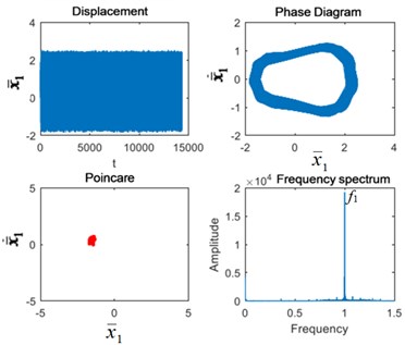
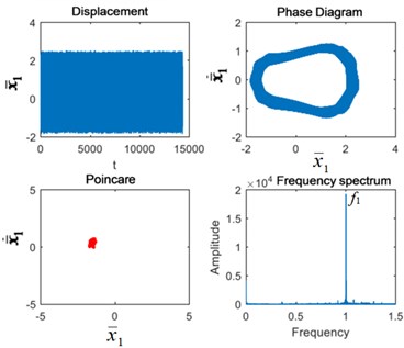
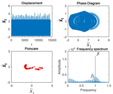
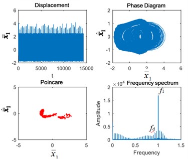
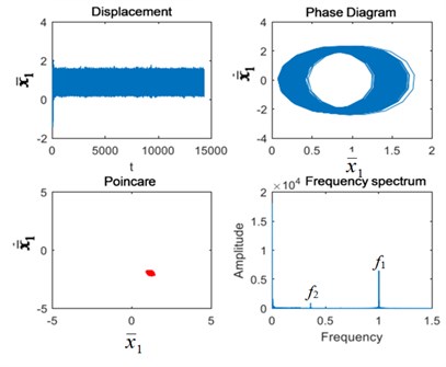
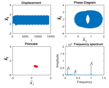
Motion characteristics of different motion states were studied respectively. The chaotic motion when excitation frequency is 0.6 (corresponding to the motor speed of 18 Hz), triple-periodic motion when excitation frequency is 1.9 (corresponding to the motor speed of 57 Hz), and quasi-periodic motion when excitation frequency is 3.5 (corresponding to the motor speed of 105 Hz) were selected for analysis. Time-domain, frequency-domain, phase diagram and Poincaré section of the 1st-stage fixed axis gear displacement in four states under three excitation frequencies were calculated respectively. The variable step Runge-Kutta method was used to solve the nonlinear differential Eq. (1), and Figs. 5-7 were obtained. The characteristic frequencies of the gears in the gear transmission system are shown in Table 3. For comparison with the experimental signals in the following, the characteristic frequency values when the motor speed is 40 Hz are listed here.
Table 3Characteristic frequencies of multistage gear transmission system
Characteristic frequency | Characteristic frequency value (Hz) | Dimensional frequency |
Meshing frequency of the 1st-stage fixed-axis gear | 1160 | 1 |
Meshing frequency of the 2nd-stage fixed-axis gear | 417.6 | 0.3599 |
Meshing frequency of the planetary gear | 101.5 | 0.0877 |
Frequency of the 1st-stage fixed-axis gear failure | 40 | 0.0345 |
Frequency of the planetary gear failure | 2.784 | 0.0024 |
From Fig. 5, we found that when the excitation frequency is 0.6, the Poincaré section is a point group under normal condition, and its main frequency characteristic is the 1st-stage fixed-axis gear meshing frequency . Due to the distance from the fixed-axis gearbox, the planetary gear failure has no obvious change in the Poincaré section and the frequency spectrum. The fixed-axis gear crack fault increases the fault period beyond the normal period. The phase diagram and Poincaré section are no longer single point cluster. There are shocks in the time domain. In the frequency domain, the 1st-stage fixed-axis gear failure frequency appears in the full frequency range. When the two fault are coupled, their characteristics are also the same as those of the fixed-axis gear crack.
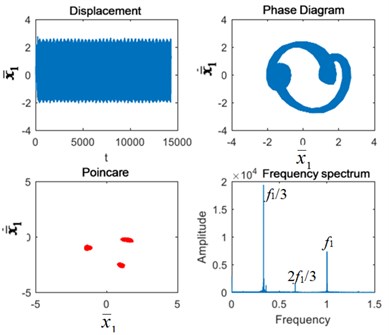
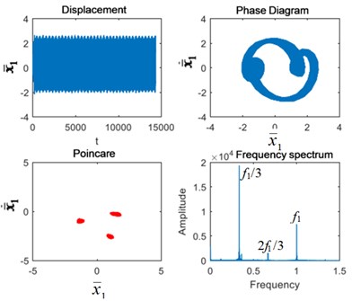
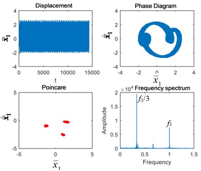
As can be seen from Fig. 6, when the excitation frequency is 1.9, the system is in triple-periodic motion, and the Poincaré section is 3-point clusters. At this time, the peak value of sub-harmonic resonance frequency /3 is the highest, followed by and 2/3. Planetary gear broken tooth failure caused little change. The failure of the fixed-axis gear crack intensified the impact. The 3-point clusters in the Poincaré section increase and the failure periods occur. The vibration energy of /3 in the frequency spectrum is dispersed into the surrounding side frequency , causing the amplitude of /3 to decrease. The coupling fault characteristics are still the same as those of the fixed-axis gear crack.
Fig. 5Vibration characteristics when Ω1= 0.6: a) normal state, b) planetary gear broken tooth fault state, c) fixed axis gear crack fault state, and d) two faults coupling
a)
b)
c)
d)
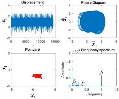
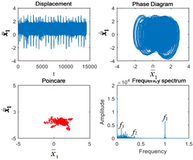
As can be seen from Fig. 7, when the excitation frequency is 3.5, the system returns to quasi-periodic motion and the Poincaré section remains a point cluster. In the spectrum diagram, the 1st-stage fixed-axis gear meshing frequency has the highest amplitude. In addition, there is the 2nd-stage fixed-axis gear meshing frequency in the spectrum diagram. When the planet gear is broken, the planet gear meshing frequency and its frequency multiplication 2 and 3 appears in the system, and Poincaré section clusters increase. Under the fixed axis gear crack fault, the fixed axis fault frequency appears at low frequencies, and the point cluster of the Poincaré section continues to increase. Under coupling fault, planetary gear fault feature and its frequency doubling 2 and 3 appear at low frequency, and fixed axis fault feature also appears. In the time domain diagram, the impact amplitude increases again, and the Poincaré section point cluster also increases.
Therefore, it can be seen that planetary gear fault features have transmission characteristics and will occur simultaneously with fixed-axis gear fault features. However, fault characteristics of the planetary gear seem to be only sensitive to high speed, which is not easy to detect when the speed is low, but appears after the speed is increased. Fault characteristics of fixed axis are just the opposite. At low speed, the amplitude changes greatly, and the influence frequency band is wide. At high speed, the amplitude increase is not much, and the influence frequency band is narrow. When the two are coupled, if the speed is too low, only the characteristics of the fixed axis can be found without the characteristics of the planetary gear. Only at high speed both can occur.
Fig. 6Vibration characteristics when Ω1= 1.9: a) normal state, b) planetary gear broken tooth fault state, c) fixed axis gear crack fault state, and d) two faults coupling
a)
b)
c)

d)
Fig. 7Vibration characteristics when Ω1= 3.5: a) normal state, b) planetary gear broken tooth fault state, c) fixed axis gear crack fault state, and d) two faults coupling
a)
b)
c)
d)
4. Experimental fault analysis
The test rig in Fig. 1 was tested and analyzed in four states. The faulty gears with fixed axis gear crack and broken tooth of the planetary gear are shown in Figs. 2 and 3 respectively. The signals of the 0-40 Hz (limited by the maximum speed of the motor) motor speed-up process were tested and analyzed. The acceleration sensor was used for signal acquisition. As can be seen from Table 3, the maximum characteristic frequency is 1160 Hz. So the sampling frequency was set to 3000 Hz.
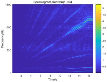
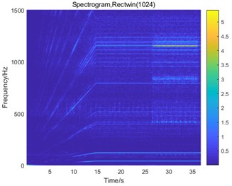
Fig. 8STFT of the vibration signals: a) normal state, b) planetary gear broken tooth fault state, c) fixed axis gear crack fault state, and d) two faults coupling
a)
b)
c)
d)
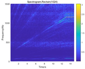
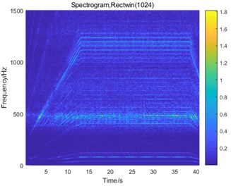
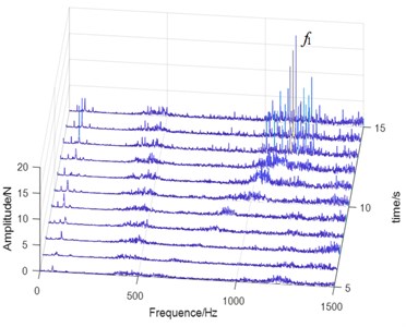
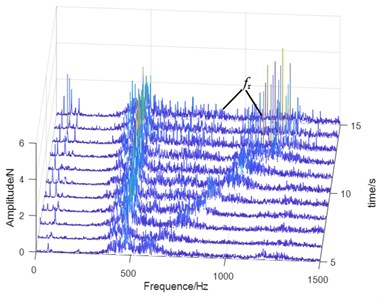
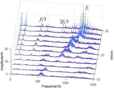
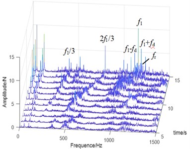
In order to study the coupling fault characteristics of the system, the short-time Fourier transform (STFT) and waterfall plot were used to process and analyze the test signals, which can distinguish the structural vibration frequency from the characteristic frequency varying with the rotating speed. As the vibration of the planetary gear is weak and difficult to identify, the axial measuring point of the planetary gearbox is selected for testing. STFT and waterfall plots of the vibration signals in normal, planetary gear broken tooth, fixed axis gear crack fault and two faults coupling state are shown in Figs. 8 and 9.
Fig. 9Waterfall plots of the vibration signals: a) normal state, b) planetary gear broken tooth fault state, c) fixed axis gear crack fault state, and d) two faults coupling
a)
b)
c)
d)
From Fig. 8, we found that the main peak value of the system under normal and planetary gear broken tooth fault state is the 1st-stage meshing frequency (1160 Hz), followed by the planetary gear meshing frequency (101.5 Hz). These two frequencies change with the speed. Two interval sections 420-500 Hz and 1250-1500 Hz which do not change with the rotation speed are natural frequencies. The 420-500 Hz interval is the natural frequency of the planetary gearbox, which is more prominent in the planetary gear broken tooth signal (Fig. 8(b)). The 1250-1500 Hz interval is the natural frequency of the fixed-axis gearbox and appears in the signals of the fixed-axis gearbox. When there is a fixed-axis crack fault (Fig. 8(c)), it is found that the frequency division and doubling order of the 1st-stage fixed axis meshing frequency increases, and the frequency peak /3 and its frequency doubling component are increased. As can be seen from Fig. 6, the frequency /3 is 1/3 the sub-harmonic resonance frequency. The cause of the frequency peak was found. When the two faults are coupled (Fig. 8(d)), the frequency characteristics are much more complex. Two fault characteristics appear at the same time.
In Fig. 9(b), when the planetary gear tooth is broken, a large number of side-bands with intervals of planet gear failure frequency appear in the 420-1160 Hz interval, which have many orders and scattered spectral lines. When increases with the speed of the motor, resonance occurs when it coincides with the natural frequency range of the planetary gearbox. In the vibration test of the speed rise of the test rig, the amplitude of the planetary gear meshing frequency increased, indicating that the high-speed signal is easier to identify the planetary gear failure. The natural frequencies of the planetary gearbox and the fixed axis gearbox are not obvious when the fixed axis gear cracks (Fig. 9(c)). Resonance occurs when passes the natural frequency of the planetary gear, and the peak disappears when it exceeds the resonance region. When the two faults are coupled (Fig. 9(d)), the side frequency caused by the planetary gear broken tooth fault is still obvious, and the side-band is wide and short. The failure characteristic of the fixed axis gear crack is 1/3 sub-harmonic resonance frequency /3, which is consistent with Fig. 9(c). The amplitude of its double frequency 2/3 increased obviously. The natural frequency becomes weak when the two faults are coupled. The fixed axis failure frequency and the planet gear failure frequency occur simultaneously near the frequency . Based on the coupling effect, the amplitude energy of is dispersed into the surrounding side-bands. Compared with Fig. 9(c), the amplitude of decreases. When and 2/3 pass through the natural frequency of planetary gear, resonance occurs, and the peak disappears when they exceed the resonance region.
Through STFT and waterfall plot, the fault characteristics of two kinds of faults can be clearly separated. The order change in the plot is observed, and frequencies varying with the rotational speed are separated from the natural frequency. The complex coupling fault signal is explained more intuitively. Through the simulation analysis of the bifurcation diagram and the Poincaré section, the cause of /3 frequency is found, and the vibration characteristic of the system with the change of excitation frequency is found.
5. Conclusions
The characteristics of coupled fault are often related. Due to the influence of the nonlinear characteristics of the system, the strength of these correlations is not constant, but varies with the excitation frequency. By analyzing the bifurcation diagram of the multi-stage gear transmission system under single and coupled fault, the influence of coupling fault on the motion state of the system can be found. The correlation between faults can be found by studying the time-frequency vibration characteristics of each motion state.
STFT and waterfall plot analysis are carried out on the experimental signals in four states to separate the two fault characteristics. We observe that 420-500 Hz and 1250-1500 Hz are the natural frequencies of the system. 420-500 Hz is the natural frequency of the planetary gearbox, which is more prominent in the signal of the planetary gearbox. The 1250-1500 Hz interval is the natural frequency of the fixed-axis gearbox, which is obvious in the signals of the fixed-axis gearbox. Planetary gear broken tooth fault is characterized by a sideband of the planetary gear fault frequency in the 420-1160 Hz frequency band, with multiple sideband orders and scattered spectral lines. When increases with the speed of the motor, resonance occurs when it coincides with the natural frequency range of the planetary gearbox. The peak value of /3 and its frequency doubling component are increased when there is only fixed axis crack fault. Compared with the bifurcation diagram, the frequency /3 is 1/3 subharmonic resonance frequency. When the two faults are coupled, the two characteristics appear simultaneously, and the natural frequency becomes weak. This study is helpful to the separation of the coupling faults and the prediction of the system operation in the fault state.
References
-
Li Z. X., Yan X. P., Yuan C. Q., Peng Z. X., Li L. Virtual prototype and experimental research on gear multi-fault diagnosis using wavelet-autoregressive model and principal component analysis method. Mechanical Systems and Signal Processing, Vol. 25, Issue 7, 2011, p. 2589-2607.
-
Li Z. X., Peng Z. A new nonlinear blind source separation method with chaos indicators for decoupling diagnosis of hybrid failures: A marine propulsion gearbox case with a large speed variation. Chaos, Solitons and Fractals, Vol. 89, 2016, p. 27-39.
-
Li Z. X., Yan X. P., Wang X. P., Peng Z. X. Detection of gear cracks in a complex gearbox of wind turbines using supervised bounded component analysis of vibration signals collected from multi-channel sensors. Journal of Sound and Vibration, Vol. Vol. 371, 2016, p. 406-433.
-
Li Y., Shao R., Cao J. A new and effective method of gear fault diagnosis using wavelet packet transform combined with support vector machine. Journal of Northwestern Polytechnical University, Vol. 28, 2010, p. 530-535.
-
Li X., Chen Y., Zhang S. Hybrid fault diagnosis algorithm based on fusion decision of multiple LS-SVM classifiers. Journal of Vibration and Shock, Vol. 32, 2013, p. 159-164.
-
Zhao H. M., Liu H. D., Xu J. J., Deng W. Performance prediction using high-order differential mathematical morphology gradient spectrum entropy and extreme learning machine. IEEE Transactions on Instrumentation and Measurement, Vol. 69, Issue 7, 2020, p. 4165-4172.
-
Deng W., Zhao H. M., Zou L., Li G. Y., Yang X. H., Wu D. Q. A novel collaborative optimization algorithm in solving complex optimization problems. Soft Computing, Vol. 21, Issue 15, 2017, p. 4387-4398.
-
Pan H., Ma Q. Research on gear-box fault diagnosis method based on adjusting-learning-rate PSO neural network. Journal of Donghua University, Vol. 23, 2006, p. 29-32.
-
Feng Z. P., Liang M. Complex signal analysis for planetary gearbox fault diagnosis via shift invariant dictionary learning. Measurement, Vol. 90, 2016, p. 382-395.
-
Wu F., Meng G. Compound rub malfunctions feature extraction based on fullspectrum cascade analysis and SVM. Mechanical Systems and Signal Processing, Vol. 20, 2006, p. 2007-2021.
-
Lei Y., He Z., Zi Y. Application of a novel hybrid intelligent method to compound fault diagnosis of locomotive roller bearings. Journal of Vibration and Acoustics, Vol. 130, Issue 3, 2008, p. 034501.
-
Fu X. Q., Jia W. T., Xu H., Song S. L. Imbalance-misalignment-rubbing coupling faults in hydraulic turbine vibration. Optik, Vol. 127, Issue 8, 2016, p. 3708-3712.
-
Wang N. F., Jiang D. X. Vibration response characteristics of a dual-rotor with unbalance-misalignment coupling faults: Theoretical analysis and experimental study. Mechanism and Machine Theory, Vol. 125, 2018, p. 207-219.
-
Lees A. W. Misalignment in rigidly coupled rotors. Journal of Sound and Vibration, Vol. 305, Issues 1-2, 2007, p. 261-271.
-
Xu M., Marangoni R. D. Vibration analysis of a motor-flexible coupling-rotor system subject to misalignment and unbalance. Part I: theoretical model analysis. Journal of Sound and Vibration, Vol. 176, Issue 5, 1994, p. 663-679.
-
Wei J., Zhang A. Q., Qin D. T., Shu R. Z. Coupling vibration analysis for planetary gear system considering flexible structure. Journal of Mechanical Engineering, Vol. 53, Issue 1, 2017, p. 1-12.
-
Wang Q. B., Li Z. W., Ma H., Wen B. Effects of different coupling models of a helical gear system on vibration characteristics. Journal of Mechanical Science and Technology, Vol. 31, Issue 5, 2017, p. 2143-2154.
-
González-Cruz C. A., Jáuregui-Correa J. C., Domínguez-González A., Lozano-Guzmán A. Effect of the coupling strength on the nonlinear synchronization of a single-stage gear transmission. Nonlinear Dynamics, Vol. 85, Issue 1, 2016, p. 123-140.
-
Wang X. Stability research of multistage gear transmission system with crack fault. Journal of Sound and Vibration, Vol. 434, 2018, p. 63-77.
-
Zhu C. C., Huang Z. H., Tang Q., Tan Y. H. Analysis of nonlinear coupling dynamic characteristics of gearbox system about wind-driven generator. Journal of Mechanical Engineering, Vol. 41, Issue 8, 2005, p. 203-207.
-
Cristián M. V. Vibration characteristics of single-stage planetary gear transmissions. Revista Chilena De Ingeniería, Vol. 22, Issue 1, 2014, p. 88-98.
-
Li Z. X., Jiang Y., Hu C., Peng Z. Recent progress on decoupling diagnosis of hybrid failures in gear transmission systems using vibration sensor signal: a review. Measurement, Vol. 90, 2016, p. 4-19.
-
Li Z., Ge S., Zhu H. Key issues in the wear fault monitoring and diagnosis for critical components of coal cutters under deep coal seam. Tribology, Vol. 34, Issue 6, 2014, p. 729-730.
-
Li Z. Y., Zhao H. D., Zeng R. L., Xia K. W., Guo Q., Li Y. H. Fault identification method of diesel engine in light of pearson correlation coefficient diagram and orthogonal vibration signals. Mathematical Problems in Engineering, Vol. 2019, 2019, p. 2837580.
-
Liang P., Long X. F., Fan F. M. Fault diagnosis of steam-turbine rotor vibration based on fractal correlation dimension. Huanan Ligong Daxue Xuebao/Journal of South China University of Technology (Natural Science), Vol. 34, Issue 4, 2006, p. 85-90.
-
Du B. Q., Tang G. J., Shi J. J. Improved algorithm for correlation dimension in vibration signal fault diagnosis. Asia-Pacific Power and Energy Engineering Conference, Wuhan, 2011.
-
Liu H. M., Zhang J. C., Cheng Y. J., Lu C. Fault diagnosis of gearbox using empirical mode decomposition and multi-fractal detrended cross-correlation analysis. Journal of Sound and Vibration, Vol. 385, 2016, p. 350-371.
-
Fei C. W., Bai G. C. Wavelet correlation feature scale entropy and fuzzy support vector machine approach for aeroengine whole-body vibration fault diagnosis. Shock and Vibration, Vol. 20, Issue 2, 2013, p. 341-349.
-
Hong K. X., Huang H. Power transformer fault diagnosis based on vibration correlation analysis. ASME International Mechanical Engineering Congress and Exposition, 2014.
-
Liang X. H., Ming J. Z., Mayank P. Analytically evaluating the influence of crack on the mesh stiffness of a planetary gear set. Mechanism and Machine Theory, Vol. 76, 2014, p. 20-38.
-
Wang X. A study on coupling faults’ characteristics of fixed-axis gear crack and planetary gear wear. Shock and Vibration, Vol. 2018, 2018, p. 4692796.
Cited by
About this article

This research is supported by Natural Science Basic Research Program of Shaanxi (Program No. 2019JQ-898) and Natural Science Research Project of Shaanxi Provincial Department of Education (Program No. 19JK0912), China.
