Abstract
Measurements of dynamics of rollers and their segments in the direction of transverse axis of rotation of eight cassettes of folding machines were carried out in this work. Measurements were carried out in pre-selected positions of rollers and their segments for two different rotating velocities of the rollers. In the first case the roller was rotated at 9 m/min velocity and in the second – at 90 m/min. It was determined that before renewal some rotating rollers for the investigated velocity of rotation of the roller 90 m/min experienced the displacements up to 80 μm. The displacements (beatings) of the rollers and their segments originating during the process of rotation in the direction of transverse axis of rotation have substantial effect to the quality of folding of printing products. Numerical investigation of the rollers was performed by using the axisymmetric model. Supplementary stiffness from the static loading caused by centrifugal forces is taken into account. The eigenmodes are calculated. The standing waves on the surface of the roller are investigated.
1. Introduction
Folding of various printing products (books, leaflets, brochures and etc.) is a typical technological operation in post-printing processes. Thus some authors [1-5] have experimentally and numerically analyzed the effect of characteristics and composition of paper, of coating layer and its properties to the final quality of printing products as the paper passes through the folding rollers. Other authors [6-11] have analyzed the motion of the paper through the folding rollers and pockets. However the final look of printing product strongly depends not only on the good characteristics of paper, but also on the quality of operation of a folding machine.
There are two standard methods applied for paper folding after the printing process – knife and pocket folding. But in both cases the press sheet is folded when it moves through the rotating folding rollers 6 and 7 (see Fig. 1). Also the press sheet depending on its folding diagram and purpose can be folded up to 6 times according to the fold marks. Thus vibrations in the folding machine may cause displacements of folding rollers or their segments. The displacements of rollers or their segments may cause deviations of fold marks in press sheets when the displacements are too big.
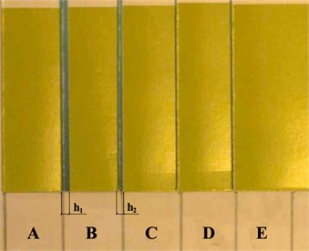
External images of such deviations of folded printing products are shown in Fig. 2. The sample A is used as a standard, i.e. it corresponds to the case of quality folding. Meanwhile the samples B, C, D and E are from the same material and they have a waste of one sort or another.
The biggest deviation of folded printing products is for the samples B (1.5 mm) and C (0.5 mm) (see Fig. 2). Deviation of the edge of other analyzed samples is relatively small and does not exceed ~0.1 mm.
Fig. 1Kinematic schemes of different folding types in folding unit: 1, 2 – feed rollers; 3 – pocket; 4 – base; 5 – second pocket, 6, 7 – folding rollers; L – press sheet
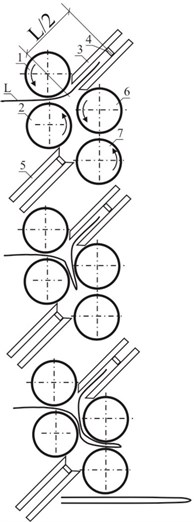
a) Single folding
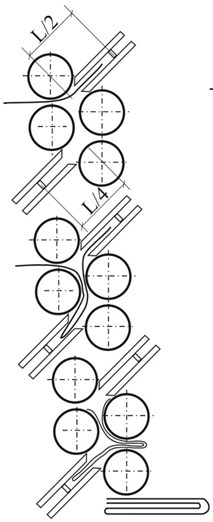
b) Double folding
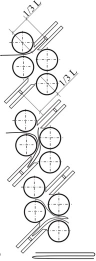
c) Parallel folding
One of the aims of this paper is to determine the displacements of rollers of pocket folding machine and of their segments in the transverse direction of geometrical axis in the process of their rotation, because they are the cause of low quality of folding.
As seen from Fig. 1 dynamic behavior of rollers plays an important role in the process of operation of the folding machine. Thus it is important to analyze the vibrations of a single roller in more detail. Axisymmetric model is used in the investigation. Supplementary stiffness from the static loading caused by centrifugal forces is taken into account. The eigenmodes are calculated. The standing waves on the surface of the roller are observed and investigated.
Numerical procedure is based on the material described in [12-14].
Fig. 2Assessment of folding quality: A-E – samples used for assessment of quality; h1 and h2 – deviations of edge of the printing product
2. Description of the folding machine and experimental setup
The pocket folding machine produced by Herzog & Heymann was used for the testing. 20 pre-selected positions were distinguished before carrying out the measurements of displacements of the rollers. Equipment used for investigations is presented in Fig. 3. From Fig. 3(a) and Fig. 3(b) it is seen that the rotating rollers and their vibrations play an important role in the process of operation of the folding machine.
Thus investigations of vibrations of the rollers are performed numerically as well as experimentally.
Fig. 3View of equipment used for the investigations: 1 – laser head for measurement of displacements “Microtrack LTC 200-100”; 2 – computer
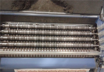
a) External view of 8 pockets of the folding machine
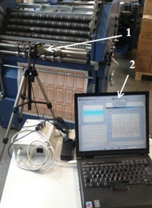
b) Equipment used for research
3. Numerical investigation of vibrations of a rotating element in a folding machine
From Fig. 1, Fig. 3(a) and Fig. 3(b) the importance of investigation of vibrations of the rotating element in a folding machine is seen.
Dynamic behavior of rollers plays an important role in the process of operation of the folding machine. Thus it is important to analyze the vibrations of a single roller in more detail. Axisymmetric model is used in the process of investigations. Supplementary stiffness from the static loading caused by centrifugal forces is taken into account. The eigenmodes are calculated. The standing waves on the surface of the roller are observed and investigated.
3.1. Numerical model for the analysis of vibrations of a rotating structure
denotes the radial coordinate, denotes the axial coordinate and denotes the coordinate in the angular direction. The stiffness matrix has the form:
where is the matrix of elastic constants and:
where , ,…, are the shape functions of the two dimensional Lagrange quadratic finite element.
The loading vector of centrifugal forces for the angular velocity 1 rad/s has the form:
where is the density of material of the structure and:
By solving the static problem the vector of nodal displacements is determined. The supplementary stiffness matrix has the form:
where:
where the stresses in the latter expression are determined from:
The total stiffness matrix corresponding to rotation by the angular velocity has the form
The mass matrix has the form:
3.2. Eigenmodes of the rotating element of the folding machine
The radius of the structure is 0.04 m and the length is 0.45 m. Both displacements are assumed equal to zero at both ends of the center line. At the remaining nodes of the centerline radial displacements are assumed equal to zero. The following parameters are assumed: modulus of elasticity 6∙108 Pa, Poisson’s ratio 0.3, density of the material 785 kg/m3.
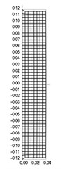
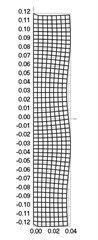
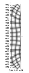
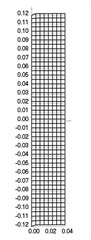
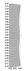
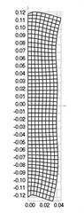
The first nine eigenmodes when 0 rad/s are presented in Fig. 4.
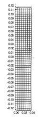
Fig. 4Eigenmodes when the structure does not rotate: a) the first, b) the second, …, i) the ninth eigenmode

a)
b)

c)
d)
e)
f)
g)
h)

i)
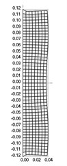
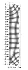
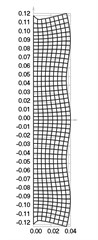
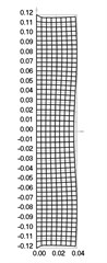
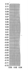
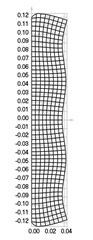
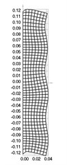
Fig. 5Eigenmodes when the structure rotates: a) the first, b) the second, …, i) the ninth eigenmode
a)

b)
c)
d)
e)
f)
g)
h)
i)
The first nine eigenmodes when rad/s are presented in Fig. 5.
From the performed investigation it was determined that centrifugal forces have effect to the eigenfrequencies and eigenmodes of the structure. But their effect to the general shape of the eigenmodes is not very great and in general the corresponding eigenmodes look similar. Standing waves on the surface of the roller are clearly seen in some of the higher eigenmodes. They influence the quality of operation of the investigated device.
4. Experimental method of investigation of dynamics of the folding machine
The diagram of positions where measurements are performed is shown in Fig. 6(a). A set of four rollers that has 11 continuous segments (see Fig. 3(a)) was investigated, but the scheme in Fig. 6(a) was split into parts. Only 16 positions of measurement are shown in the scheme, the last 4 were as follows:
• 3rd position: core of 3rd roller, 26 cm from the left edge;
• 7th position: 13th rubber segment from the left edge of the 1st internal (solid) roller;
• 19th position: 13th rubber segment from the left edge of the 1st internal (solid) roller;
• 20th position: 10th rubber segment from the left edge of the 3rd internal (solid) roller.
Measurements of rollers and their segments were carried out using the displacement measurement laser head “Microtrack LTC 200-100” (see Fig. 3(b)). Characteristics of the laser head are listed in Table 1.
Fig. 6Diagrams of measurement: a) diagram of measurement positions of rollers and their segments; b) scheme of main parameters on a measurement signal: marking of displacements: 0 – 0 – geometrical axis of rotation of the rollers; Δ1max – maximum displacement in the positive direction; Δ2max – maximum displacement in the negative direction
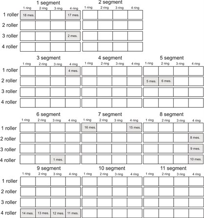
a)
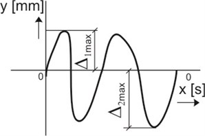
b)
Table 1Characteristics of laser head “Microtrack LTC 200-100”
Characteristics | Value |
Wavelength, nm | 670 |
Measurement distance, mm | 200 |
Laser beam diameter, μm | 120 |
Measurement resolution, µm | 10 |
Sampling frequency, kHz | 40 |
Numerical values of displacements were obtained by carrying out the calculations based on the scheme shown in Fig. 6(b). The results of measurements of displacements of the rollers were determined by choosing maximum displacements in the positive direction of the axis and maximum displacements in the negative direction of the axis.
Velocity of folding depends on the complexity of folding diagram of final printing product. Based on the experience of the operators of pocket folding machines the following conclusion is valid: the more fold marks the lower velocity should be used. Thus measurements by using the laser head were carried out by rotating the rollers at two different velocities – 9 m/min and 90 m/min.
Rotating the rollers at different velocities measurements were performed at the following positions: 1, 3, 7, 8, 9, 11, 14, 16 and 18. Also measurements at the same positions were carried out after the set of folding rollers was renewed. The structure of measurement system is shown in Fig. 7(a).
Laser displacement converter “Microtrack LTC 200-100” and laser sensor of rotations “PRK318” were used in the second stage of measurements of geometrical displacements of rollers of the folding machine. Measurement signals from both converters were digitized in the device for data collection as well as processed and visualized using the computer by applying appropriate software. The laser displacement converter is supplementary controlled by using a control unit (see Fig. 7(b)).
Fig. 7Diagrams of measurement systems: a) structure of first stage of measurements: 1 – folding roller; 2 – segment of the folding roller; 3 – working segment; 4 – laser measurement head “Microtrack LTC 200-100”; control unit – laser head controller; DAQ – data acquisition unit; PC – personal computer with signal processing software; b) structure of second stage of measurements: 1 – folding roller; 2 – segment of the folding roller; 3 – working segment; 4 – reflector; 5 – laser measurement head; 6 – laser throttle sensor; control unit – laser head controller; DAQ – data acquisition unit; PC – personal computer with signal processing software
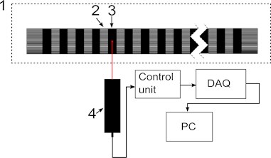
a)
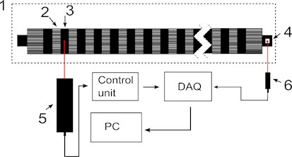
b)
Laser beam of the converter of displacements in the process of measurements was directed to the working surfaces of the bending segments. This enabled the measurement not only of the displacements of the surface of the roller segments, but also to measure the non-uniformities of their surfaces. Both measurements were performed in the process of operation of the machine. Numerical investigations of vibrations of rollers were performed by determining their eigenfrequencies and eigenmodes. Similar non-uniformities of the surfaces of the roller are observed in the eigenmodes presented there.
The laser beam of the sensor of rotations was directed to the reflecting element glued on the roller. This solution in the procedure of measurement enabled to have a definite mark of the start of rotation of the roller. The advantage of this mark is the possibility to separate the displacements of the segments of roller in each turn around. Thus there is a possibility to perform averaging of the measurements from more than one turn around thus reducing the random error of measurements.
The obtained results of measurements were processed using low pass filter, thereby excluding the components of low frequency corresponding to the displacements of the roller and its segments during measurement. Numerical investigations of vibrations of rollers were performed by determining their eigenfrequencies and eigenmodes. Here the vibrations with the eigenfrequencies determined previously are to be excluded by using a low pass filter.
Low pass filter was designed using “Matlab Filter Design & Analysis tool”. The properties of low pass filter were chosen according to the frequency of rotation of the roller. At the velocity of 90 m/min rotating frequency of the roller is 10 Hz. In order to extract the roller displacement, which is related to the geometry of the roller, from obtained measurement signal, FIR equiripple low pass filter was designed with frequency parameters: Fpass: 30 Hz, Fstop: 150 Hz.
Some of the measurements were performed at the velocity of the roller 9 m/min. At this slower velocity frequency of rotation was 1 Hz. The parameters of the filter were related to the frequency of rotation and recalculated accordingly: Fpass: 3 Hz, Fstop: 15 Hz.
5. Results of investigation of dynamics of the folding machine and discussions
Results of measurement of displacements of the rollers when they are rotating at a velocity of 9 m/s in the position 16 before and after renewal of the rollers are presented in Fig. 8. In Table 2 generalized results of displacements of the rollers (before renewal) are presented.
Table 2 presents the summarized results of measurement of displacements of the rollers and of their segments before renewal.
The mean maximum double displacement listed in the Table 2 is the mean value of differences between outermost displacement points of geometrical axis of the segment/roller. Maximum displacement is the biggest displacement of geometrical axis of the segment/roller in the direction of the positive axis and – in the direction of the negative axis.
Results of measurement of displacements of the rollers when they are rotating at a velocity of 90 m/s in the position 16 before and after renewal of the rollers are presented in Fig. 9.
Fig. 8Results of measurement of displacements of segment of the rollers at the velocity of 9 m/min: measurement position 16; 1 – after renewal; 2 – before renewal
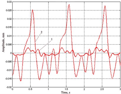
Fig. 9Results of measurement of displacements of segment of the rollers at the velocity of 90 m/min: measurement position 16; 1 – after renewal; 2 – before renewal
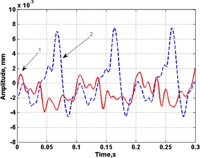
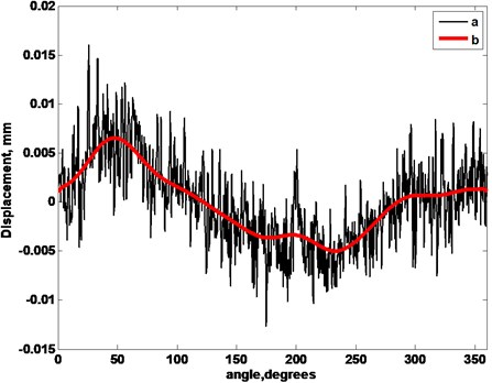
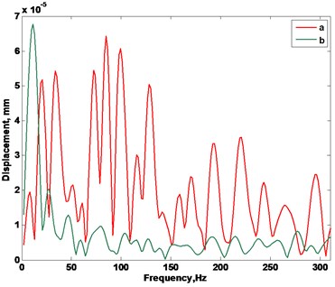
Typical displacements of the segments of both rollers and their frequency spectrum are represented in Figs. 10-12. In Fig. 10 and Fig. 11 the changes of geometry of the segments during one turn around are shown. Those displacements (see Fig. 10 and Fig. 11, curves a) are obtained after performing the averaging of the obtained displacements during 100 periods of rotation of the roller. The displacements reflect the non-uniformities of the surfaces of the segments and their surface roughness. The low frequency part of the obtained displacement was separated using the low frequency filter of 30 Hz (see Fig. 10 and Fig. 11, curves b). This low frequency part reflects the displacements of the segments of the roller in the process of turning around.
Table 2Summarized results of measurement of displacements of the rollers before renewal
Measurement position | Rotating the rollers at 9 m/min velocity | Rotating the rollers at 90 m/min velocity | ||||
Mean maximum double displacement, mm | Maximum displacement, mm | Mean maximum double displacement, mm | Maximum displacement, mm | |||
1 | 0.04 | 0.02 | –0.02 | 0.04 | 0.03 | –0.02 |
3 | 0.01 | 0.01 | –0.01 | 0.02 | 0.01 | –0.01 |
7 | 0.02 | 0.01 | –0.01 | 0.02 | 0.01 | –0.01 |
8 | 0.09 | 0.05 | –0.04 | 0.09 | 0.05 | –0.04 |
9 | 0.06 | 0.04 | –0.03 | 0.07 | 0.04 | –0.03 |
11 | 0.06 | 0.01 | –0.05 | 0.07 | 0.02 | –0.05 |
14 | 0.03 | 0.02 | –0.01 | 0.03 | 0.02 | –0.02 |
16 | 0.04 | 0.03 | –0.02 | 0.05 | 0.03 | –0.02 |
18 | 0.04 | 0.02 | –0.03 | 0.04 | 0.02 | –0.02 |
The frequency spectrums of the previously presented displacements are shown in Fig. 12. Spectrum from the segment of the first roller (before renewal) indicates that the surface of the segment is non uniform and because of this fact the constituent parts of multiple frequencies are seen in the spectrum. In the spectrum of the segment from the second renewed roller the constituent part of the frequency of rotation is evident and other constituent parts of the spectrum are comparatively small.
The investigated displacements and their frequency spectrums indicate that the segment from the roller before renewal has the surface that is not as uniform as the surface of the segment in a renewed roller. Low frequency displacement indicates that a segment before renewal also has higher amplitude of displacement during the process of rotation.
Fig. 10Measured displacements during turn around of the roller 1 in the 3rd measurement position: a – the obtained displacement, b – the low frequency part of the displacement
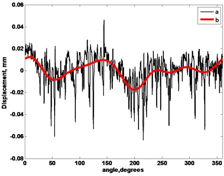
Fig. 11Measured displacements during turn around of the roller 2 in the 10th measurement position: a – the obtained displacement, b – the low frequency part of the displacement
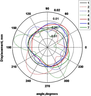
In Fig. 13-Fig. 15 polar diagrams are presented in which the displacements of the surfaces of separate segments on the basis of the filtered low frequency displacements are shown. In Fig. 13 as well as in Fig. 15 measurements of the segments on the boundaries are presented, while in Fig. 14 measurements of the segments from the middle are presented.
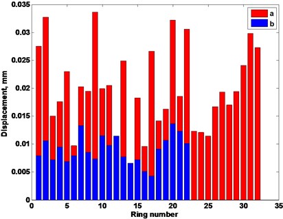
Values of double amplitude of displacements of all the measured segments are indicated in Fig. 16.
Results of measurements presented in Fig. 16 indicate that all the displacements of segments of the roller before renewal during the process of operation of the machine exceed the displacements of the renewed roller.
Fig. 12Spectra of measured displacements: a – of the 3rd measurement position of roller 1, b – of the 10th measurement position of roller 2
Average displacement of the segments of the roller before renewal is 0.0199 mm and standard deviation is 0.0073 mm. Average displacement of the segments of the renewed roller is 0.0090 mm and standard deviation is 0.0025 mm.
Thus the folding of printing products is performed with higher quality when the displacements of the renewed roller do not exceed the displacements mentioned above.
Fig. 13Displacements of the surfaces of the segments of the rollers: 1 – trajectory of the surface of the ideal segment, 2 – displacements of the 1st segment of the roller 1 (before renewal), 3 – displacements of the 2nd segment of the roller 1, 4 – displacements of the 3rd segment of the roller 1, 5 – displacements of the 1st segment of the renewed roller 2, 6 – displacements of the 2nd segment of the roller 2, 7 – displacements of the 3rd segment of the roller 2
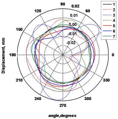
Fig. 14Displacements of the surfaces of the segments of rollers: 1 – trajectory of the surface of the ideal segment, 2 – displacements of the 15th segment of the roller 1 (before renewal), 3 – displacements of the 16th segment of the roller 1, 4 – displacements of the 17th segment of the roller 1, 5 – displacements of the 10th segment of the renewed roller 2, 6 – displacements of the 11th segment of the roller 2, 7 – displacements of the 12th segment of the roller 2
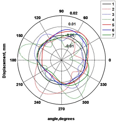
Fig. 15Displacements of the surfaces of the segments of rollers: 1 – trajectory of the surface of the ideal segment, 2 – displacements of the 30th segment of the roller 1 (before renewal), 3 – displacements of the 31st segment of the roller, 4 – displacements of the 32nd segment of the roller 1, 5 – displacements of the 20th segment of the renewed roller 2, 6 – displacements of the 21st segment of the renewed roller 2, 7 – displacements of the 21st segment of the renewed roller 2
6. Conclusions
When rollers and segments are rotating with the help of the motor at the velocities of 9 m/s and 90 m/s the biggest average maximum displacements of the geometrical axis were measured in the positions 8, 9, 11 (0,07-0,09 mm). The smallest average maximum displacements of the geometrical axis were measured in the positions 1, 3, 7, 14, 18 (0,02 – 0,04 mm). On the basis of the data of the producer of the bending machine Herzog & Heymann the allowable tolerance of the segment rollers is 0÷0,005 mm. The performed measurements of the displacements of the segment rollers enable to make a conclusion that the determined displacements substantially exceed the tolerance limit of the rollers. Because of this fact it is impossible to ensure qualitative bending of polygraphic materials by this machine.
Fig. 16Displacement amplitudes of the segments of rollers: a – before renewal, b – after renewal
The results of measurements show evident differences between the renewed roller and the roller before renewal. The surface of segments of roller before renewal is of greater roughness and not as uniform when compared with the renewed roller. Analysis of geometry of the segments indicated that the segments of the roller before renewal experience higher displacements if compared with the segments of the renewed roller. On the average the segments of roller before renewal had the displacement of 19.9 μm and of the renewed roller had the displacement of 9.0 μm. Segments of roller before renewal also have a wider scatter of values of displacements. This may mean that the paper is caught by mutually not equal forces at different segments of the roller.
Dynamic behavior of rollers plays an important role in the process of operation of the folding machine. Thus it is important to analyze the vibrations of a single roller in more detail. Axisymmetric model is used in the process of investigations. Supplementary stiffness from the static loading caused by centrifugal forces is taken into account. The eigenmodes are calculated. It was determined that centrifugal forces have effect to the eigenfrequencies and eigenmodes of the structure. Their effect to the general shape of the eigenmodes is not very great and in general the corresponding eigenmodes look similar. Standing waves on the surface of the roller are clearly seen in some of the higher eigenmodes. They influence the quality of operation of the investigated device.
References
-
Huang H., Hagman A., Nygards M. Quasi static analysis of creasing and folding for three paperboards. Mechanics of Materials, Vol. 69, Issue 1, 2014, p. 11-34.
-
Barbier C., Larsson P. L., Östlund S. Numerical investigations of folding of coated papers. Composite Structures, Vol. 67, Issue 4, 2005, p. 383-394.
-
Barbier C., Larsson P. L., Östlund S. On dynamic effects at folding of coated papers. Composite Structures, Vol. 67, Issue 4, 2005, p. 395-402.
-
Barbier C., Larsson P. L., Östlund S. Experimental investigation of damage at folding of coated papers. Nordic Pulp and Paper Research Journal, Vol. 17, Issue 1, 2002, p. 34-38.
-
Sim K., Youn H. J., Oh K. D., Lee H. L., et al. Fold cracking of coated paper: the effect of pulp fiber composition and beating. Nordic Pulp and Paper Research Journal, Vol. 27, Issue 2, 2012, p. 445-450.
-
Dai J. S., Medland A. J., Mullineux G. Carton erection using reconfigurable folder mechanism. Packaging Technology and Science, Vol. 22, Issue 7, 2009, p. 385-395.
-
Yao W., Cannella F., Dai J. S. Automatic folding of cartons using a reconfigurable robotic system. Robotics and Computer – Integrated Manufacturing, Vol. 27, Issue 3, 2011, p. 604-613.
-
Mullineux G., Feldman J., Matthews J. Using constraints at the conceptual stage of the design of carton erection. Mechanism and Machine Theory, Vol. 45, Issue 12, 2010, p. 1897-1908.
-
Sirkett D. M., Hicks B. J., Berry C., Mullineux G., Medland A. J. Simulating the behavior of folded cartons during complex packing operations. Proceedings of the Institution of Mechanical Engineers, Part C: Journal of Mechanical Engineering Science, Vol. 220, Issue 12, 2010, p. 1797-1811.
-
Liu H., Dai J. An approach to carton – folding trajectory planning using dual robotic fingers. Robotics and Autonomous Systems, Vol. 42, Issue 1, 2003, p. 47-63.
-
Gidlöf V. In press conditions and their effect on runnability and convertability in digital package printing. Packaging Technology and Science, Vol. 18, Issue 4, 2005, p. 189-197.
-
Bathe K. J. Finite Element Procedures in Engineering Analysis. Prentice-Hall, New Jersey, 1982.
-
Zienkiewicz O. C. The Finite Element Method in Engineering Science. Mir, Moscow, 1975, (in Russian).
-
Levy S., Wilkinson J. P. D. The Component Element Method in Dynamics with Application to Earthquake and Vehicle Engineering. McGraw-Hill, New York, 1976.
About this article

The work was carried out on the basis of the Contract No. F5-90-1389. The authors thank the reviewers for their valuable comments. They enabled to substantially improve the paper.
