Abstract
The productivity and capacity release of hot-strip rolling is severely limited by pendular vibration. Previous studies on mill vibration have investigated the influence of rolling parameters on vertical vibration; however, the influence of dynamic stiffness compensation factors on vertical vibration has not yet been considered owing to the limitations of modelling methods. Herein, we develop a simulation model of mill liquid–machine coupling with dynamic stiffness compensation using AMESim software. The established simulation model is used to investigate the effect of this dynamic stiffness compensation on mill vertical vibration under conditions of downfeed thickness difference excitation frequency, thickness difference excitation amplitude, thickness difference excitation phase, and dynamic stiffness compensation signal generation hysteresis. Evidently, the impact of the mill stiffness compensation on the mill vertical vibration differs with the thickness of the excitation frequency, and the impact should be discussed according to the excitation frequency segment. The amplitudes of the roll system vibration and incoming thickness difference excitation are essentially linear, whereas the excitation phase does not affect the frequency or amplitude of the mill vibration. The rolling machine stiffness compensation signal hysteresis also has a significant impact on the mill vibration amplitude. Our findings will improve the mechanism of the hot rolling process and suppress droop vibrations.
Highlights
- Our findings will improve the mechanism of the hot rolling process and suppress droop vibrations.
- A coupling simulation model of the liquid mill with rolling stiffness compensation was established, and the model parameters were determined according to the actual working state parameters of the rolling mill.
- The rolling motor stiffness control system and its related parameters are studied, and the influence of the entire dynamic stiffness compensation circuit on the vibration characteristics of the system is explored.
1. Introduction
The vibration of rolling mills is one of the most important technical problems worldwide. Severe rolling mill vibration strongly affects the surface quality of strip steel and may even damage parts of the rolling mill, thereby impacting production.
Recent theoretical studies on rolling mill vibrations have focused on monitoring and reducing rolling mill vibration, and its impact on steel production. Shi et al. [1] improved a 1D, 2D convolutional neural network using multisource sensing data, and developed a new method of depth learning to improve mill monitoring and maintenance, which further improved the efficiency and accuracy of online health monitoring of rolling mills. Whang et al. [2] quantitatively evaluated the influence of process parameters on the strip surface using a dynamic rolling force prediction model with a prediction accuracy of 90.68 %. Li et al. [3] analyzed the effect of numerous factors on the variation law of the strip amplitude based on the amplitude residual stress model of strip steel. The amplitude of the strip steel is known to increase with the aerodynamic load in the form of a quadratic polynomial, and it increases exponentially with increasing tension. Yan et al. studied three nonlinear dynamic models in the hot rolling process using the Bayesian optimization algorithm to optimize the important parameters of the limit gradient lifting. This approach significantly improved the calculation efficiency, prediction accuracy, and stability of the pre-vibration model, whereas the horizontal and vertical coupling dynamic model of the mill was established by considering the gap between the work roll and the stand. Finally, an engineering test platform was designed by combining Newmark-β numerical integration and Riccati matrix, and it was used to analyze the vibration signals of SPA-H strips with various specifications [4]-[6].
Several studies analyzed the influence of changes in the structural parameters of the rolling mill. For example, Cui et al. [7] analyzed the influence of friction on the vertical vibration of the surface of a working roll under the peeling oxide film of a 1780 mm rolling mill. Wang et al. [8] modelled the vertical vibration of a four-high rolling mill under nonlinear stiffness and analyzed the influence of various parameters on the vertical vibration using a damper optimized by an adaptive genetic algorithm. The multiscale weighted permutation entropy was used to effectively characterize rolling mill bearing faults based on the idea of multichannel signal processing [9].
Zhao et al. [10] established a predictive model of the vibration energy based on a long short-term memory neural network and verified the ability of the model to effectively predict the vertical vibration of a rolling mill using the threshold method. Masoud et al. [11] calculated the stiffness parameters of the main components of a mill using the vibration model of a thin-plate mill with two degrees of freedom, performed numerical simulation and finite element analysis, and reduced the vibration of the rolling mill. A model to predict the rolling mill vibration prediction based on an ensemble empirical mode decomposition (EEMD)-long short-term memory recurrent neural network (LSTM) has also been developed [12].
Dynamic models of rolling mills were developed to study nonlinear coupling. Using a numerical analysis method, Gao et al. [13] obtained the mode analysis of the main transmission system and the inherent attribute relationship of the system; the harmonic response analysis yielded the amplitude–frequency characteristic response curves of the components at different positions, thus providing a reference to guide the structural optimization of rolling mill parts. Wang et al. [14] employed the dynamic friction and segmented stiffness models between rolling interfaces to establish a horizontal nonlinear vibration model to study the amplitude–frequency characteristics of the horizontal vibration system of a rolling mill under conditions of a dynamic friction tertiary nonlinear term, damping term, and segmented stiffness term. Acoustic theory was applied to solve strip flutter in a rolling mill [15], thus revealing that the upper tori and upper support rollers were more sensitive to flutter and therefore suitable locations for flutter detection sensors. In the experiments, the frequency of the vibration signal in each part of the frame was in the range of the third octave chatter. Lei et al. [16] established a structure–process coupling model of the rolling process based on the improved Timoshenko beam theory which was used to study the rolling steady–state and unsteady-state processes. Analysis of the vibration characteristics of rolling mills by the time-varying oil film stiffness model of cold rolling 20 rolls was studied using elastic flow lubrication theory [17], thus providing a theoretical basis for the identification of local defects on the surface of the rolls. A study on the relationship between negative self-vibration and vertical vibration in rolling mills by Kozhevnikov et al. [18] elucidated the main causes of the vertical vibration phenomenon and identified the vibration behavior through continuous statistical processing of the rolling process parameters.
The aforementioned research demonstrates the considerable interest in the rolling mill vibration problem from scholars worldwide. Despite this considerable interest, the rolling mill vibration problem has not yet been effectively solved. Analysis of the complex coupling behavior of the hydraulic system and rolling mill structure revealed that the variation or fluctuation in some parameters of the hydraulic control system affect the precision of the automatic gauge control system. Under certain conditions, rolling mill vibrations can be increased or reduced; therefore, studying the effects of these parameters on the rolling mill vibration is of great practical significance.
2. Establishment of the analytical model
2.1. Simplification of finite element model of the whole rolling mill
Under the premise of ensuring the actual mechanical properties of the mill model, the model structure should be simplified as much as possible, this paper in the mill finite element modeling process to do 6 simplified processing:
1) Create a stepped motor shaft without changing the overall length of the main motor and rotor moment of inertia.
2) The platen, rolls and bearing seats are modeled according to the actual dimensions, and the press-down system is simplified from cylindrical to cylindrical due to the small influence of the press-down device on the dynamic characteristics of the mill as a whole.
3) The upper and lower beams are divided into shell units with a thickness of 40 mm according to the actual dimensions. Since the mill stand is divided by solid units, and the beams are divided by shell units, in order to improve the accuracy of the connection between the two with embedded processing.
4) Since the guide plate has little effect on the overall dynamic characteristics of the mill, it is ignored.
5) According to the online monitoring signal of roll gap provided by the factory, there is a gap of 3 mm between the upper and lower working rolls. At the same time, there is a gap of 1 mm between the bearing seat of the working roller, the bearing seat of the support roller and the column of the plaque.
6) Other parts are modeled according to actual dimensions, ignoring fine dimensions and chamfered structures.
2.2. Material setup and meshing of the model
In this paper, the mill stand model is made of structural steel material and its parameters are shown in Table 1.
Table 1Material setup
Target items | Target requirements |
Densities | 7850 kg/m3 |
Young’s modulus | 2E+11 Pa |
Bulk modulus | 1.6667E+11 Pa |
Shear modulus | 7.6923E+11 Pa |
Poisson’s ratio | 0.3 |
The finite element numerical integration calculations will be based on the different stiffness matrix of the cell using different solution methods, so the cell mesh is a critical step in the finite element numerical simulation analysis, which directly affects the subsequent numerical calculations of the accuracy of the analysis results and the convergence of the results.
The larger, regular cell bodies in the model are meshed using the hexahedral dominant method, which improves the accuracy and efficiency of the model by optimizing the generation of hexahedra, which automatically converts non-hexahedral cells to hexahedral cells. These conversions include voxel elimination at corners and correction of irregularly shaped voxels, which in turn improves the convergence speed of the solver. As for the irregularities at the edges of each gear pair, roller system and the transition places on the plaque, the mesh is refined by the patch-adaptive method, which decomposes the model into several small grid blocks, each of which can be individually adapted to the mesh delineation. This can reduce the mesh deformation and improve the calculation accuracy. It is worth noting that in this paper, in the mesh size adjustment, the maximum size is set to 100 mm, the mesh feature removal is set to yes, the capture curvature is set to yes, the minimum size of curvature is 1.0 mm, and the normal angle of curvature is 60.0°; whereas, in the advanced setting option, the straight-edge unit is set to no, the rigid body behavior is set to size reduction, the use of asymmetrically mapped mesh is set to no, the topology check is set to yes, and the shrinkage tolerance is set to 0.9 mm, the meshing results are shown in Table 2.
Table 2Grid division results
Target items | Target requirements |
Number of nodes | 3449397 |
Number of units | 2159823 |
Orthogonal mass | 0.90086 |
Unit size | 50 mm |
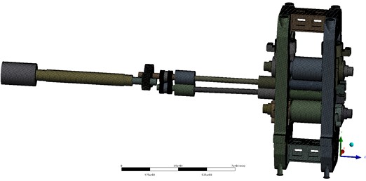
After simplification of the mill stand, material setting and meshing, the finite element model of the mill is established as shown in Fig. 1.
Fig. 1Finite element modeling of rolling mills
2.3. Analysis model of vertical resonance response of whole roll system of rolling mill
In the strip rolling process, due to the strip steel thickness fluctuations, will be in the upper and lower work rolls at the seam and the main motor to the mill caused by the rolling force and torque excitation, in the simulation of these two excitations simplified as harmonic loads, used to simulate rolling fluctuations in rolling force fluctuations and torque fluctuations, due to the complexity of the structure of the rolling mill as well as the diversity of the perturbation excitation, the vibration of its vibration is also full of versatility and uncertainty. This paper focuses on analyzing the vertical system of rolling mill pendant vibration.
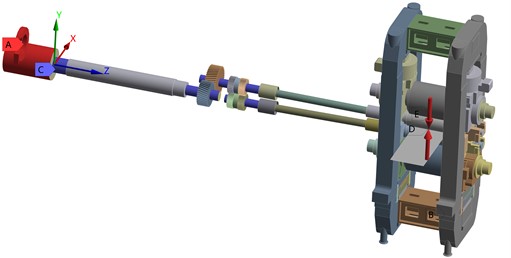
In the strip-rolling process, the rolling force and torque are excited at the gap between the upper and lower work rolls and at the main motor owing to fluctuations in the strip thickness. The main motor is used to simulate rolling force and torque fluctuations during rolling, as shown in Fig. 2. The set sweep frequency used in the harmonic response analysis was 0-200 Hz, and it was divided into 200 intervals of 1 Hz.
Fig. 2Harmonic response model of a rolling mill
The applied fluctuating load is described by Eqs. (1) and (2):
where is steady rolling force, 20000 KN; is the rolling force fluctuation, 500 KN; is the preload torque, 100 KNm; and is the torque fluctuation, 10 KNm.
The velocity-frequency response curve of the vertical vibration was obtained by observing a measurement point on the work-roll bearing pedestal on the driving side of the mill. The simulation results are shown in Fig. 3.
Fig. 3Amplitude–frequency characteristic curve of the vibration response
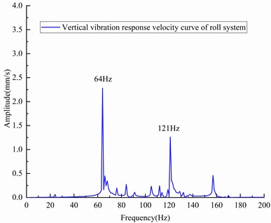
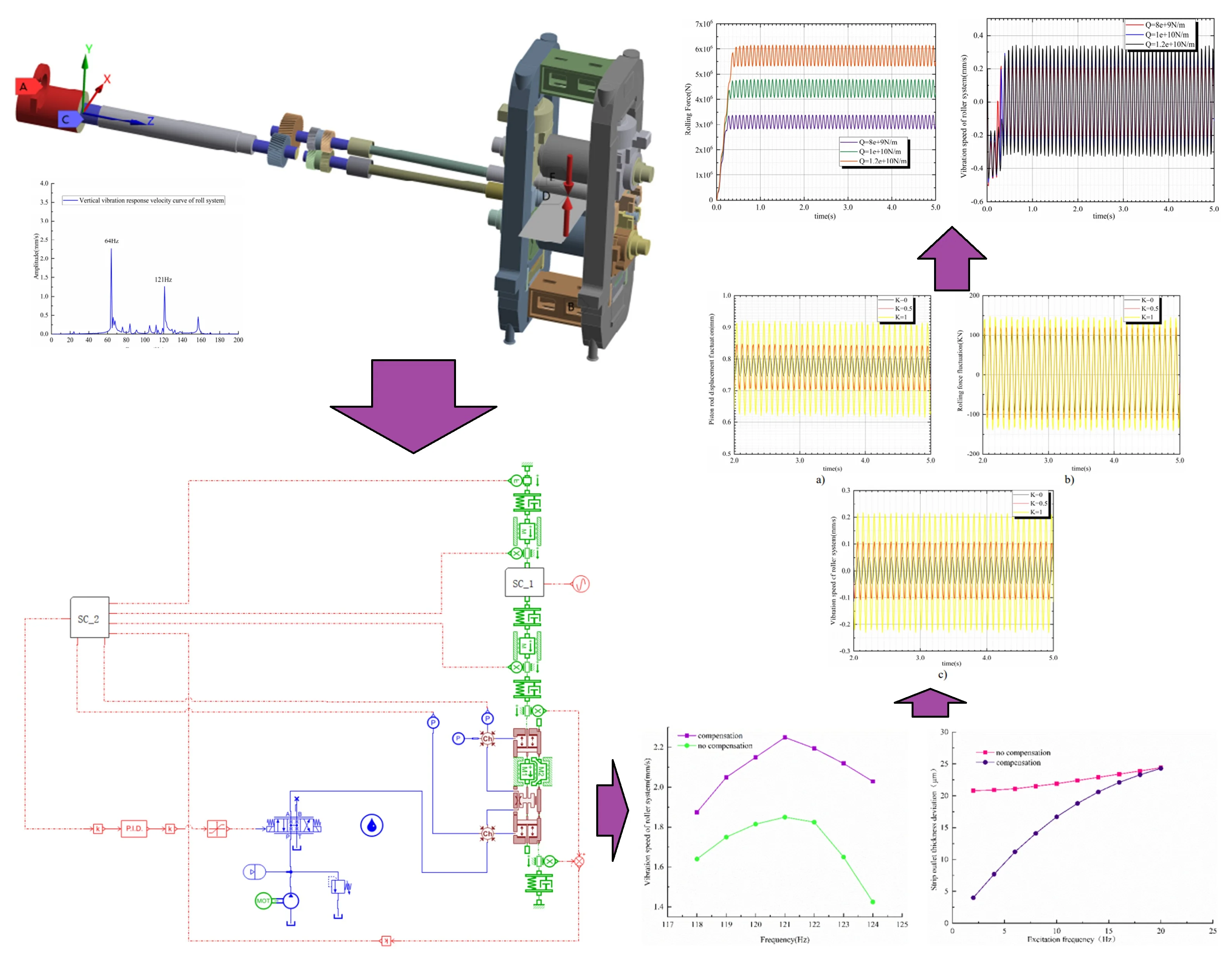
The amplitude-frequency characteristic curve of the vibration response shows that the mill has two main sensitive peak frequencies of 64 and 121 Hz in the vertical direction of the roll system; i.e., the mill is sensitive to these frequencies. Therefore, the mill produces a large vertical vibration when the external excitation frequency approaches 64 Hz or 121 Hz. These two sensitive peak frequencies were observed after long-term onsite monitoring of the mill.
2.4. Simulation model of hydraulic gap control system for a rolling mill
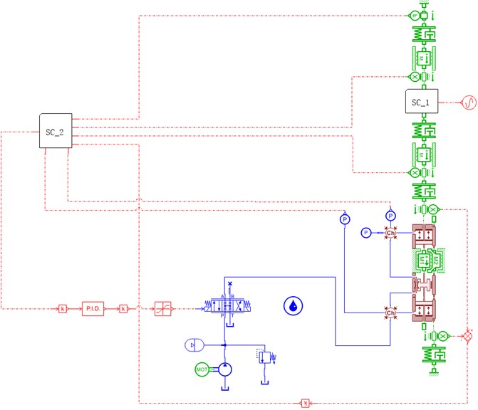
The hydraulic clearance control system controls the hydraulic reduction system according to the rolling force or reduction position calculated by the two-stage system. The hydraulic-mechanical coupling simulation model with rolling mill dynamic stiffness compensation was established based on the closed-loop position model of the hydraulic gap control system (Fig. 4), and the effect of the dynamic stiffness compensation coefficient and phase delay of the compensation signal on the rolling mill vibration was further investigated.
After establishing the hydraulic–mechanical coupling simulation model of rolling mill dynamic stiffness compensation, the true parameters were measured experimentally using a rolling mill with known specifications. To more accurately simulate a real rolling mill system, the main technical indices are listed in Table 3.
The adjusted model parameters are listed in Table 4.
Table 3Main technical indicators
Target items | Target requirements |
Accuracy standard | Steady-state error of position response <3 μm |
Closed-loop response bandwidth | 12-20 Hz |
Static stiffness of rolling mill | 810 t/mm |
One side rolling force | > 12,000 kN |
Table 4System simulation parameters
System parameters | Set value |
Roll system mass block | 68000 kg |
Hydraulic cylinder mass block | 7450 kg |
Upper roller system equivalent stiffness | 1×10¹⁰ N/m |
Equivalent stiffness of lower roll system | 7×10⁹ N/m |
Equivalent stiffness of frame | 1.26×10¹⁰ N/m |
Initial position of piston rod | 0.125 m |
150 | |
30 |
Fig. 4Hydraulic–mechanical coupling model of dynamic stiffness compensation
3. Effect of dynamic stiffness on vertical roller vibration
By analyzing the composition structure and working principle of hydraulic roll gap control system and rolling mill automatic thickness control system, a hydraulic mill coupling simulation model with rolling stiffness compensation is established, and the model parameters are determined according to the actual working state parameters of the rolling mill and the correctness of the model is verified. The rolling motor stiffness control system and its related parameters are studied, and the influence of the entire dynamic stiffness compensation circuit on the vibration characteristics of the system is explored.
3.1. Influence of thickness fluctuation excitation on vibration
The effect of the feed gauge fluctuation excitation frequency on the vertical vibration of the rolling mill was analyzed by varying the simulated fluctuation excitation frequency. Furthermore, the system vibrations with and without dynamic stiffness control compensation were compared to assess the effect of dynamic stiffness control compensation on the rolling mill vibration.
Evidently, the amplitude of the vibration increased with the excitation frequency (Fig. 5); however, the overall amplitude of the entire vibration was lower, and the mill did not experience violent vibrations.
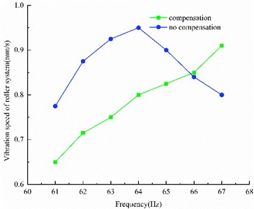
Fig. 6 shows that the amplitude of the vibration decreased, and the dominant frequency of the vibration peak changed when dynamic stiffness compensation was added under the excitation of the first-order resonance zone thickness difference, thus indicating that the rolling mill dynamic stiffness compensation may affect the resonance frequency of the rolling mill system under the examined conditions.
Fig. 5Effect of low frequency excitation on roller vibration velocity
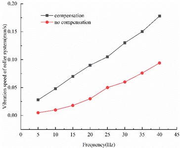
Fig. 6Influence of first-order resonance interval excitation
Evidently, the vibration of the rolling mill was aggravated by adding dynamic stiffness compensation under the excitation of the thickness difference in the second-order resonance region (Fig. 7). The vibration amplitude of the rolling mill was higher under this type of vibration mode, regardless of whether dynamic stiffness compensation was applied, and therefore had a greater impact on mill vibration.
Fig. 7Influence of second-order resonance interval excitation
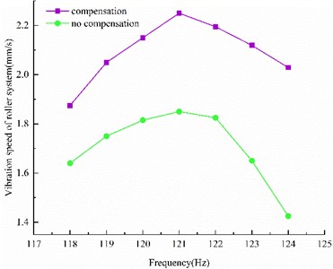
Fig. 8Influence of excitation frequency on the thickness difference fluctuation
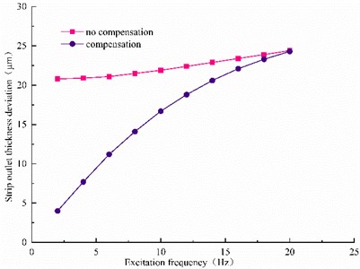
The fluctuation signal of the strip exit thickness was observed in the low-frequency excitation section where the rolling mill dynamic stiffness works well (Fig. 8). As the dynamic response of the actuator was exceeded, the thickness deviation could not be fully compensated; thus, the dynamic stiffness control system was weakened.
3.2. Influence of the amplitude of thickness difference excitation on vibration
According to a statistical analysis of the rolling field, the fluctuation amplitude of incoming thickness difference of different strips can vary between 10 and 50 μm. To study the influence of the excitation amplitude of the gauge difference on the vibration of the rolling mill, the vibrations of the lower roll system of the mill were calculated with and without dynamic stiffness compensation at various excitation amplitudes.
Evidently, under low-frequency excitation, the vibration of the roller system was enhanced by adding dynamic stiffness compensation (Fig. 9). The excitation amplitude of the incoming thickness difference increased linearly with the vibration velocity of the roll system. Additionally, with increasing excitation amplitude, the difference in vibration velocity caused by dynamic stiffness compensation increased.
Fig. 9Influence of 30 Hz thickness difference excitation amplitude on vibration
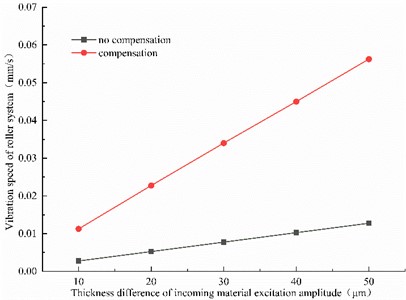
Fig. 10Influence of 64 Hz thickness difference excitation amplitude on vibration
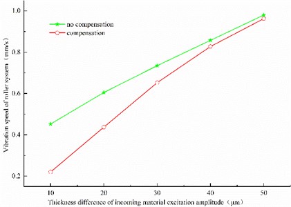
Evidently, with the increase in excitation frequency near approximately 64 Hz, both the vibration and vibration amplitude of the roller system increased (Fig. 10). Simultaneously, dynamic stiffness compensation was added to restrain vibration. Furthermore, the vibration velocity of the roll system and excitation amplitude of the incoming thickness difference exhibited a negative linear relationship.
Evidently, the vibration of the roller system was most intense when the excitation frequency was similar to the natural frequency of 121 Hz (Fig. 11). The vibration increased upon adding dynamic stiffness compensation. Thus, a linear relationship exists between the vibration velocity of the roll system and the excitation amplitude of the incoming thickness difference.
Fig. 11Influence of 121 Hz thickness difference excitation amplitude on vibration
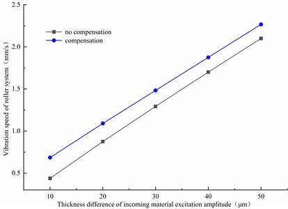
Fig. 12Effect of excitation phase change on roller system vibration
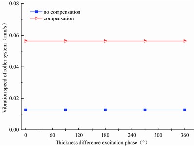
3.3. Effect of excitation phase change on vertical vibration
Fig. 12 reveals that the change in the phase excited by the gauge difference did not affect the vibration frequency or amplitude of the rolling mill, and the vibration effects on the system were identical.
3.4. Influence of dynamic stiffness parameters on vertical vibration
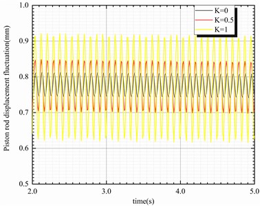
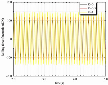
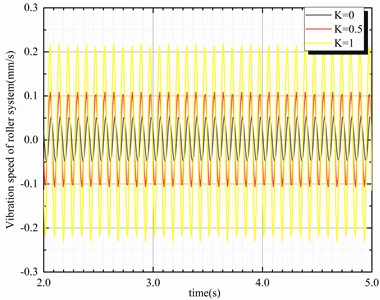
When the thickness deviation is in the low-frequency range and the dynamic stiffness compensation is effective (for example, at 30 Hz), the dynamic stiffness compensation coefficient changes as described by the hydraulic–mechanical coupling simulation model with dynamic stiffness compensation, where represents the variable stiffness compensation coefficient. This model can be applied to determine the natural, hard, and superhard characteristic when is 0, 0.5 and 1, respectively, thereby obtaining the simulation curves of the parameters of the coupling system. The piston rod displacement, rolling force fluctuation, and roll system vibration signals of the system model are shown in Fig. 13.
Fig. 13Curves of parameters with various dynamic stiffness compensation coefficients
a)
b)
c)
A plot of the piston rod position with as a function of the dynamic-stiffness compensation coefficient is presented in Fig. 13. Evidently, the displacement fluctuation of the piston rod and the rolling force fluctuation, both increased with the dynamic stiffness compensation coefficient. Furthermore, the variation in velocity of the roller system with the dynamic stiffness compensation coefficient was elucidated, and the steady amplitude of the system was found to be proportional to the dynamic stiffness compensation coefficient.
4. Effect of dynamic stiffness compensation phase lag on vertical vibration
Evidently, the amplitude of the vibration velocity of the roller system changed periodically with the hysteresis phase; however, the amplitude of the vibration was not significantly affected under the first mode of excitation at 64 Hz (Fig. 14(a)). Similarly, the lag phase of the compensation signal had little effect on the vibration of the rolling mill, whereas the amplitude of the rolling mill vibration was affected by changing the lag phase of the compensation signal under the second order vibration mode at an excitation frequency of 121 Hz (Fig. 14(b)). Thus, the effect of feedback phase hysteresis on the vertical vibration of the rolling mill differs according to the vibration mode. Subsequently, relevant vibration suppression measures can be considered by changing the lag phase of the compensation signal.
Fig. 14Effect of excitation frequency and phase hysteresis on vibration velocity
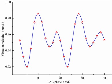
a) 64 Hz
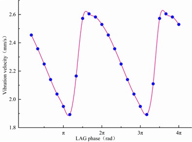
b) 121 Hz
4.1. Effect of strip plasticity coefficient on vertical vibration
In the hydraulic–mechanical coupling simulation model with dynamic stiffness compensation, the stiffness the model spring, which represents the plastic coefficient of the strip steel, was varied.
The rolling force signal of the head in the system model is illustrated in Figure 15. Evidently, the rolling force signal of the three different strip steels with different plastic stiffnesses appeared at a vibration frequency of 64 Hz vibration. The rolling force signal increased with the plastic stiffness of the strip steel, which increased the steady rolling force and rolling force fluctuation.
Fig. 15Rolling force curve under different strip plasticity coefficient
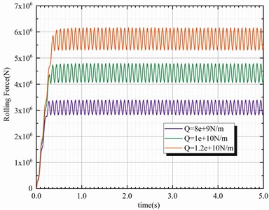
Fig. 16Vibration velocity curve of the roller system with various strip plasticity coefficients
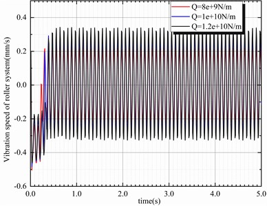
Evidently, the vibration signal at 64 Hz also appeared in the roll system (Fig. 16), and the severity of the vibration of the rolling mill increased with the plastic coefficient of the strip. Generally, when the strip is thinner, cooler, and harder, its plasticity coefficient is higher, thus increasing the likelihood that the mill will vibrate during the rolling process.
5. Discussion
1) The effect of mill AGC is limited by the dynamic response of the actuator. Through simulation, it is found that in different thick difference excitation frequency bands, the effect of dynamic stiffness compensation is different, in the rolling mill motor stiffness compensation can work well in the low-frequency band, the dynamic stiffness compensation of the mill vibration belongs to the positive feedback, the addition of dynamic stiffness compensation will exacerbate the vibration of the rolling mill.
2) When the excitation frequency in the resonance frequency band of the mill, different vibration type under the role of dynamic stiffness compensation effect is different, and sometimes even the opposite effect. When the excitation frequency is higher, the rolling machine dynamic stiffness compensation has lost its effect. When the incoming material thickness difference excitation amplitude increases, the roll system vibration speed will also increase, the two basic linear relationship, but different excitation frequency band to change the excitation amplitude, with or without dynamic stiffness compensation caused by the mill vibration amplitude gap will be different.
3) It is found through simulation that the effects of dynamic stiffness compensation coefficients on the mill fluid-machine coupled system at different excitation frequencies are different and also need to be discussed in segments. In addition, changing the hysteresis phase of dynamic stiffness compensation at different excitation frequencies will have different effects on the mill vertical vibration.4. The limitation of the simulation analysis is that it does not consider the influence of other interference excitation sources and strip friction and wear on the stiffness compensation of rolling maneuver, which will be the focus of future research work.
6. Conclusions
This paper studies the phenomenon that the vibration amplitude of the rolling mill changes when a hot rolling mill switches on and off MMC, and focuses on exploring the influence of rolling motor stiffness control on the coupling vertical vibration of the rolling mill fluid to obtain the influence law of the vertical vibration of the rolling mill, and then provides a theoretical basis for the next step to propose measures to suppress the vibration of the rolling mill, and the main conclusions are as follows:
1) A coupling simulation model of the liquid mill with rolling stiffness compensation was established, and the model parameters were determined according to the actual working state parameters of the rolling mill.
2) The rolling motor stiffness control system and its related parameters are studied, and the influence of the entire dynamic stiffness compensation circuit on the vibration characteristics of the system is explored.
In this paper, only the influence of dynamic stiffness compensation on the vertical vibration of the rolling mill is analyzed, and future research will mainly focus on the influence of its dynamic stiffness compensation on the torsional vibration of the rolling mill.
References
-
P. Shi, Y. Yu, H. Gao, and C. Hua, “A novel multi-source sensing data fusion driven method for detecting rolling mill health states under imbalanced and limited datasets,” Mechanical Systems and Signal Processing, Vol. 171, p. 108903, May 2022, https://doi.org/10.1016/j.ymssp.2022.108903
-
C. Wang and M. Zhang, “Research on dynamic rolling force prediction model based on CNN-BN-LSTM,” Journal of Advanced Mechanical Design, Systems, and Manufacturing, Vol. 16, No. 3, pp. JAMDSM0029–JAMDSM0029, Jan. 2022, https://doi.org/10.1299/jamdsm.2022jamdsm0029
-
H. Li, G. Han, J. Yang, N. Li, and J. Zhang, “Study on amplitude and flatness characteristics of elastic thin strip under fluid-structure interaction vibration excited by unsteady airflow,” Metals, Vol. 9, No. 5, p. 496, Apr. 2019, https://doi.org/10.3390/met9050496
-
Y. Zhang, R. Lin, H. Zhang, and Y. Peng, “Vibration prediction and analysis of strip rolling mill based on XGBoost and Bayesian optimization,” Complex and Intelligent Systems, Vol. 9, No. 1, pp. 133–145, Jun. 2022, https://doi.org/10.1007/s40747-022-00795-6
-
J.-X. Cui, Y. Peng, and J. Wang, “Instability of roll nonlinear system with structural clearance in rolling process,” Journal of Iron and Steel Research International, Vol. 30, No. 1, pp. 112–125, Aug. 2022, https://doi.org/10.1007/s42243-022-00816-1
-
S. Lin, J. Sun, C. Zhao, and Y. Peng, “Research on dynamic characteristics of the RBBH system based on dynamics model and vibration data fusion,” Sensors, Vol. 22, No. 10, p. 3806, May 2022, https://doi.org/10.3390/s22103806
-
J. Cui, Y. Peng, J. Wang, and D. Hu, “Study on work roll vertical vibration under periodic spalling of the oxide film,” Tribology Transactions, Vol. 65, No. 5, pp. 827–838, Sep. 2022, https://doi.org/10.1080/10402004.2022.2100853
-
M. Wang, H. Xu, D. He, T. Wang, and J. Zhang, “Design of a damped vibration absorber to control the resonant vibration of roll,” Mechanical Systems and Signal Processing, Vol. 178, p. 109262, Oct. 2022, https://doi.org/10.1016/j.ymssp.2022.109262
-
C. Zhao, J. Sun, S. Lin, and Y. Peng, “Rolling mill bearings fault diagnosis based on improved multivariate variational mode decomposition and multivariate composite multiscale weighted permutation entropy,” Measurement, Vol. 195, p. 111190, May 2022, https://doi.org/10.1016/j.measurement.2022.111190
-
X.-Y. Wang, Z.-Y. Gao, and Y.-L. Xin, “Multi-source heterogeneous time series data processing and chatter prediction based on the method of FDA-LSTM in cold rolling processes,” SN Applied Sciences, Vol. 5, No. 5, pp. 202–210, Apr. 2023, https://doi.org/10.1007/s42452-023-05353-4
-
M. Mosayebi, F. Zarrinkolah, and K. Farmanesh, “Calculation of stiffness parameters and vibration analysis of a cold rolling mill stand,” The International Journal of Advanced Manufacturing Technology, Vol. 91, No. 9-12, pp. 4359–4369, Feb. 2017, https://doi.org/10.1007/s00170-017-0026-6
-
R. C. Zhang and Z. X. Cao, “Research on vibration prediction for tandem cold rolling mill based on EEMD-LSTM,” Forging and Stamping Technolog, Vol. 47, No. 9, pp. 174–181, 2022.
-
C. Y. Gao, J. X. Li, and Y. P. Wei, “Numerical simulation on torsional vibration response of main drive system of rolling mill and structural failure analysis,” Chinese Journal of Applied Mechanics, Vol. 39, No. 2, pp. 268–273, 2022.
-
Y. T. Wang, L. Wang, and J. Y. Tian, “Analysis on horizontal vibration behavior of hot rolling mill based on dynamic fiction and piecewise stiffness,” Forging and Stamping Technology, Vol. 47, No. 2, pp. 200–206, 2022.
-
M. R. Niroomand, M. R. Forouzan, and A. Heidari, “Experimental analysis of vibration and sound in order to investigate chatter phenomenon in cold strip rolling,” The International Journal of Advanced Manufacturing Technology, Vol. 100, No. 1-4, pp. 673–682, Sep. 2018, https://doi.org/10.1007/s00170-018-2639-9
-
L. Cao, X. Li, and D. Zhang, “Research into the effect of flatness control actuators on vibration stability in cold rolling using the finite element method,” The International Journal of Advanced Manufacturing Technology, Vol. 125, No. 1-2, pp. 245–266, Dec. 2022, https://doi.org/10.1007/s00170-022-10593-6
-
S. Wu, W. Xing, Y. Liu, and Y. Shao, “Research on dynamic characteristics and identification method of local defect on the roll surface,” Engineering Failure Analysis, Vol. 121, p. 105063, Mar. 2021, https://doi.org/10.1016/j.engfailanal.2020.105063
-
A. V. Kozhevnikov, A. S. Smirnov, I. A. Kozhevnikova, P. V. Antonov, S. V. Zhilenko, and A. I. Aralov, “Investigation of self-oscillations and the development of a procedure of stabilization of the process in a continuous mill for strip cold rolling,” Metallurgist, Vol. 64, No. 7-8, pp. 770–779, Nov. 2020, https://doi.org/10.1007/s11015-020-01053-1
-
Y. Zhang, W. Wang, H. Zhang, H. Li, C. Liu, and X. Du, “Vibration monitoring and analysis of strip rolling mill based on the digital twin model,” The International Journal of Advanced Manufacturing Technology, Vol. 122, No. 9-10, pp. 3667–3681, Sep. 2022, https://doi.org/10.1007/s00170-022-10098-2
-
L.-Y. Jiang, T. Zhen, J.-B. Huang, Y.-Y. Wei, H. Li, and L.-F. Ma, “Calculation and analysis of rolling force during aluminum alloy thick plate snake/gradient temperature rolling with different roll diameters,” The International Journal of Advanced Manufacturing Technology, Vol. 115, No. 11-12, pp. 3453–3465, Jun. 2021, https://doi.org/10.1007/s00170-021-07244-7
Cited by
About this article

This research is supported by the Fundamental Research Fund Project of Central Universities (Grant No. FRF-AT-19-001).
The datasets generated during and/or analyzed during the current study are available from the corresponding author on reasonable request.
Lidong Wang: conceptualization, writing-original draft preparation, visualization, project administration; Peng Hou and Chengzhen Wang: writing-original draft preparation, visualization; Xiaoqiang Yan: writing-review and editing, supervision; Shen Wang: writing-review and editing, supervision; Xiaoling Wang: writing-review and editing, supervision.
The authors declare that they have no conflict of interest.
